The ALFA Laser and Analysis Tools
Abstract
The optimal performance of adaptive optics systems can only be maintained if the wavefront reference is bright and compact. Experience has shown that both of these important criteria are remarkably difficult to achieve with laser guide stars, and this contribution gives an account of the methods by which ALFA attempts to reach them. First, the production of a high quality, high power laser beam is described. However, this quality is unavoidably compromised along the path to the launch telescope. In order to rectify this, a new set of diagnostic tools which monitor the quality of the out-going beam has been installed, and these are also described. Lastly, we outline a number of possible modifications on which we are working. If successful, these may allow a substantial improvement in the beam quality.
keywords:
adaptive optics, laser guide star, atmospheric turbulence1 Introduction
The aim of the ALFA laser guide star (LGS) is the generation of an artificial reference star for the adaptive optics (AO), in order to increase the sky coverage of the system. For best results the Shack-Hartmann sensor of the AO system needs a sufficiently bright compact source to obtain centroid measurements with a good signal-to-noise ratio. So the main objective is: how to get the brightest and smallest LGS image on the wavefront sensor. The heart of the ALFA laser facility is an argon ion pumped dye jet laser, which is installed in the coudé lab at the Calar Alto 3.5-m telescope. The laser emits light at the wavelength of the sodium D2 line with an output power up to 4 W, with extremely high beam quality. In order to create an artificial guide star in the mesospheric sodium layer, the laser beam is transported from the laser laboratory along the coudé path of the 3.5-m to a Galilean beam expander near the main mirror of the telescope, where it is finally launched (see Ott et al., this issue). Along this path, a distance of approximately 50 m, the laser is subjected to the disturbing influence of the turbulent air inside the dome and other distortion sources, so that the beam quality is significantly worse than when it leaves the coudé lab. The aberrations can affect the brightness and compactness of the laser guide star, as shown in Figure 1, which are so critical to the performance of the adaptive optics (see Davies et al., this issue). A series of diagnostic tools have therefore been installed directly beneath the launch telescope to allow monitoring of the quality of the projected beam.
2 The Laser
The main component of the ALFA laser system is a Coherent 899 ring dye laser, pumped by a Coherent INNOVA 200 Argon ion laser. These lasers, together with optics for beam forming and diagnostics, are mounted on a floated optical bench (Figure 2) in a separate room on the coudé floor, and shielded with removeable covers. Above the dye laser a laminar flow box is installed to prevent the sensitive resonator components from contamination by, for example, dust in the air. The laser room is equipped with an air conditioning system to stabilize the air temperature to 201∘C independent of the environmental conditions.
The lasing medium in the ring dye laser is Rhodamine 6G (Rh6G). For exiting Rh6G, intense blue or green light is necessary. Today only continuous wave ion lasers are able to produce high enough power in that wavelength regime in a good single-spatial mode. The quality of the pump laser (power stability, mode structure) is important because the dye laser output is influenced by the input of the pump laser as well as the flow characteristics of the dye jet. The multiline output of the ALFA pump laser consists of eight lines from 457.9–514.5 nm which lase simultaneously so that, although their relative line strengths are not ideally matched to the absorption band of Rh6G, the power output is maximised.
The pump laser provides 27 W of multi-line output, about 2 W of which is fed directly into the coudé train to be used as a pilot beam for alignment, and the rest pumps the dye ring laser. This is sufficient for a dye laser output of typically 3.8 W, with single spatial and temporal mode quality. Higher powers (up to 5.5 W) can be achieved but at the cost of considerably higher maintenance overheads [Quirrenbach et al. (1997)].
2.1 Argon-Ion pump laser
The cavity of the pump laser consists of a low pressure plasma tube with ionized argon gas as the active lasing medium positioned between one flat high reflector and one curved output coupler. The adjustable high reflector is sealed onto the plasma tube. Between the front Brewster window and the output coupler there are an intracavity aperture, a manual shutter and a beamsplitter for power monitoring. The intracavity aperture is adjusted for the largest aperture diameter that provides the highest output power (for a given tube current) with a Gaussian TEM00 mode.
The plasma tube of the pump laser is cooled in a closed loop water cooling system (flow rate 25 l min-1). The heat exchanger, as well as the chiller for the dye solution are installed in the water supply cabin which is adjacent to the laser lab to prevent interference with the running system. The water tubes are shielded by separate pipes which can withstand a tube leakage, and are mounted under the floor of the laser cabin.
The microprocessor controlled power supply of the pump laser provides the DC current for the tube and its axial electro-magnet, and is equipped with a circuit breaker and a 480/380 V transformer. It is located in different room and monitors safety interlocks (covers, water flow) and diagnoses system faults. Communication is either via a serial link or with a remote control module.
During normal operation of the system, the pump laser status, its tube current, tube voltage, and output power are monitored continuously using a serial line. Changing any of these parameters is only possible using the remote control module which is located next to the pump laser in the laser laboratory, so as to prevent damage from excessive tinkering.
2.2 Ring Dye Laser
The basic design of any continuous wave dye laser is constrained by the photophysics and chemistry of the dissolved organic dye molecules, which represent the active laser medium. The absorption and emission spectra of dissolved dye molecules are broadband features, a result of the fact that in a dye solution the closely spaced rotational-vibrational levels are heavily collision broadened such that they overlap. The absorption band at lower frequencies is nearly the mirror image of the emission band, and the exact peak position of these bands depend on the solvent and dye concentration.
The broadening of the gain of organic dyes is both a blessing and a curse. It is a blessing in the sense that in the case of homogenous broadening all of the gain medium can contribute power to the oscillating laser mode, and because the broad emission spectrum provides the laser’s tunability. It is a curse because the broad spectral width means that the lifetime of the excited-state is short and hence intense pump powers are required in order to achieve sufficient population inversion for the laser oscillation.
The major elements of the ring dye laser are:
-
•
The resonator which is a figure-8-shaped ring, formed with 3 spherical mirrors and one flat output coupler with 10% transmission
-
•
A curved mirror which focuses the pump light into the free flowing dye jet stream, which is the active medium of the dye laser
-
•
The dye circulator which cools, filters and pumps the dye solution
Because of the heat produced in the dye by the focused pump light which is not re-radiated as fluorescence and also because of triplet-state trapping, it is necessary to have the dye molecules traverse the pump spot very rapidly. The excited dye molecules can decay into both singlet- and triplet-states. But due to the much longer lifetime of the triplet-states, these act as a trap for the excited dye molecules, which are then no more available for the lasing process. Therefore the flow velocity at the output of the jet-forming nozzle of the dye laser is such that the dye molecules stay only in the pump spot for a time similar to the triplet-lifetime. Additionally, triplet-state trapping can further be quenched chemically by adding some amount of cyclo-octatetraene (COT) to the dye solution.
The dye solution is kept at a constant temperature with a chiller installed in the water supply cabin. The materials coming into contact with the dye in the circulation system (stainless steel, teflon) are chosen such that they do not influence the lifetime of Rh6G, which is therefore subject to degradation only due to pump-laser heating and laser-induced photochemistry.
The transmitted fraction of the pump light (several Watts) falls onto a water-cooled beam-stop in the dye laser head. The pump laser shutter is automatically closed in case of a failure of the dye circulation system.
A number of modifications (dye solvent, flow velocity, temperature, pump focus spot size, etc.) to the original design, aimed at optimising the output power were made and are elaborated in Quirrenbach et al. (1997).
2.3 Output Beam
In order to provide efficient excitation of the sodium in the mesosphere, the laser must have a single spatial and temporal mode quality. The former criterion is achieved by ensuring that the pump lases only in the Gaussian TEM00 mode. The latter is attained with a pair of low-finesse etalons and a birefringent filter, which restrict the bandwidth to about 10 MHz; it can also be tuned using the scanning Brewster plate and a piezo-mounted mirror (M3 in Figure 2). Although in principle it is possible to reduce the bandwidth to 1 MHz, this is unnecessary since the radiative lifetime due to spontaneous emission from the 3P level of the atom is 16 ns, giving a natural (homogenous) linewidth of almost exactly 10 MHz. The tuning is stabilised using a reference cavity, to which 1.4% of the beam power is diverted. This compares the directly-measured flux in the beam to that passing through a temperature- and pressure-controlled etalon. It is designed so that the 589.2 nm line lies at the half-maximum transmission of one of the etalon orders, providing a monotonic relation between beam frequency and transmitted power. For absolute frequency tuning and long-term stabilisation the cavity is locked to the Lamb dip in the fluorescence signal from a sodium cell. Thus the laser can be de-tuned away from the Na line for diagnostic purposes.
Scanning the laser across the frequencies over which sodium fluorescence is expected to occur shows an intriguing result. It is well known that the 589.2 nm line is a doublet with separation 1.77 GHz, and that the lower energy transition has a doppler-broadened absorption cross-section greater by a factor of 1.7. The frequency scan in Figure 3 reflects this, but with an absorption cross-section ratio of nearly a factor 4; the laser is very effective at pumping this transition.
The next component on the optical bench is a shutter (lower right in Figure 2) which allows the laser to be shut off in an emergency, when an aircraft is detected or when moving the telescope or dome.
The output from the dye laser is plane-polarised, and at this stage a quarter-wave plate circularly polarises it. This is an important issue because, as mentioned above, the 2S1/2 ground state of the Na atom is split into a doublet with a separation much greater than the laser line-width. The laser is tuned to excite atoms from the higher angular momentum level (with peak absorption into 3P ). Since they can decay back to either the or levels, after a few cycles the whole population will reside in the level, resulting in a significant loss of pump efficiency even though the atoms are replenished by high altitude winds. On the other hand, if the laser beam is circularly polarised so that it imparts angular momentum to the atoms, they will tend to decay back to the level, increasing the efficiency. Measurements by [Ge et al. (1997), Ge et al. (1998)] at the MMT have shown that the brightness of a compact LGS can be increased by 30% in this way. There are two restrictions on the gains we can achieve. Firstly, between the coudé lab and the launch telescope there are many reflections so that the final polarisation state of the beam is uncertain, probably elliptical. Secondly, polarisation only becomes an important issue if the beam is close to saturating the Na layer, otherwise the loss of atoms from the state is a minor effect. Nevertheless, the first results, given in Section 3.5 are very convincing.
In the last part of the laser optical bench the beam is pre-expanded to 15–30 mm diameter, and it is then fed into the coudé train.
3 Beam Diagnostics
In traversing the beam relay from the coudé lab to the launch telescope, the beam suffers power loss and wavefront aberrations from multiple reflections and dome turbulence. It is therefore essential to monitor the quality of the projected beam immediately prior to its launch. For this reason, a diagnostics bench has been installed directly beneath the launch telescope.
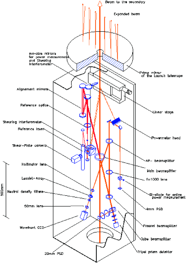
Before describing the individual components, it is worth mentioning the general layout of the system which is shown in Figure 4. For the different tasks the instruments have to be fed with light from the laser beam, but without disturbing the propagation to the launch telescope and without noticeably reducing the power. For this purpose the analysis is performed on a small amount of light which is split off with a high quality, antireflection coated optical wedge plate at the center of the optical bench; and the polarization detector, which is mounted at the top of the beam expander, is built as small as possible. The diverted beam feeds all instruments which are continuously needed for beam control and online measurements. Several mirrors are mounted on a linear stage and can be moved into the laser beam, to do measurements that are only needed from time to time. Because the diameter of the laser can be adapted with a pre-expander in the coudé lab to different seeing conditions, the instruments have been designed so that they are not influenced by these changes.
3.1 Position measurement
Operation of the laser guide star requires the laser to remain steady on the optical axis of the launch telescope, but several different influences can affect this:
-
1.
Errors can occur when feeding the beam into the coudé path.
-
2.
The coudé path changes while the telescope is tracking.
-
3.
Turbulence in the dome may cause fast deviations in the beam position.
-
4.
There will be some flexure in the telescope structure and instabilities of mechanical components.
To minimize beam degradation due to these effects, active control of the beam position is needed. As discussed in Ott et al. (this issue), the beam path is equipped with four fast steering mirrors to keep the laser on the optical axis. As well as these, to position the laser accurately on the optical axis of the launch telescope, detectors for all four degrees of freedom are installed at the analysis bench. One two dimensional PSD at the focus of a 1 m focal length lens is capable of measuring angular deviations down to 0.4′′. The x-y position is measured with a triple prism splitter, positioned out of the focal plane of a short focal length lens, acting rather like a quad-cell. In addition a further PSD at a 100 mm focus is used for coarse alignment, in case the laser is moved out of the field of view of the other much more sensitive detectors. To provide an absolute reference, a helium-neon laser is aligned to the optical axis of the launch telescope, so the detectors can be calibrated with the signal from this light. Measurements of the laser movement and tip-tilt measurements of the back scattering from the mesospheric sodium can be compared with the help of these tools, and a distinction between the influences of atmospheric turbulence and the turbulence in the telescope dome is possible. An example of the tip-tilt movement and the power spectrum (with the beam relay control loop open) is given in Figure 5.
3.2 Power
From the laser laboratory to the launch telescope 6 mirrors and 3 windows are installed in the telescope dome. Due to dust the mirrors surface quality tends to degrade with time, so the overall transmission of the relay system decreases. To have a monitor for this and to know the absolute power of the light propagating upward, a bolometric power meter is installed, to which the laser can be fed with the help of a dielectric, spherical mirror on the linear stage. Because this power measurement is not in use permanently an additional photo diode serves as a relative online power monitor. The typical power of the laser at the launch telescope is about 2.5 W, according to an overall transmission of the relay path of 60%. But this number may vary from 50% with strong dust coverage, to 75% with freshly cleaned mirrors.
3.3 Shearing interferometer
The diameter of the laser is adapted to the actual seeing conditions with a beam expander at the laser lab, requiring the beam to be re-collimated after every adjustment. In order to do this quickly and easily, another mirror at the linear stage can reflect the light to a shearing interferometer which is watched by a camera. The angle of the fringes indicates how well collimated the beam is, with perfect collimation occuring when they lie parallel to the dark line bisecting the interferogram, as in Figure 6. In addition, the shape of the fringes indicates whether abnormal static distortions are present; in this case they suggest significant aberrations arising from optical elements in the beam path, such as the window at the end of the pipe from the coudé lab.
3.4 Wavefront sensing and beam profile
For the higher orders of the wavefront distortion we have installed a Shack-Hartmann sensor at one analysis beam. The sensor consists of a lenslet array in a collimated beam of 3–5 mm with arrays of to subapertures, one relay lens, one neutral density filter and a CCD camera in the focal plane. With this sensor, direct measurements of the dynamic wavefront distortions can be made before the laser is finally launched (static aberrations cannot be measured due to lack of a suitable reference beam). Preliminary measurements, such as those in Figure 7, showed an unexpectedly large distortion which reached mean values of up to 0.7 (at 589 nm). However, more recent measurements indicate that these are untypical and that the normal wavefront error is only 0.1, far too small to account for the observed LGS size.
The intensity distribution across the beam diameter, which is also an interesting parameter in propagation calculations, can be measured with the same CCD camera with better spatial resolution by removing the lenslet array. An additional CCD camera is planned, so that the intensity profile and the wavefront can be measured simultaneously.
3.5 Polarization
The polarization dependence of the resonant backscattering in sodium vapor and the mesospheric sodium layer has been reported by several authors (eg. \opencitesho90; \opencitebal80; \opencitehap72; \opencitehaw55). For studies on these effects and for the automatic angular control of a quarter wave plate a photo polarimeter has been constructed and installed. Two types of instruments have been tested: A division of amplitude polarimeter, and one with a rotating analyzer. Both instruments are capable of determining a set of parameters that describe the complete state of polarization of any elliptically polarized light. While the advantage of the rotating analyzer lies in easier calibration, the less complicated mechanics and lower sensitivity to intensity fluctuations made the division of amplitude polarimeter the choice to install at the exit of the launch telescope. First measurements of the dependence of the sodium response to the polarization were made in September 1998, and are presented in Figure 8. They show the remarkable result that as much as a factor 2 increase in returned flux can be achieved by circularly rather than linearly polarising the projected beam.
4 Planned Upgrades
There are numerous problems associated with using mirrors to direct the laser beam to the telescope: alignment, active mirror control, jitter, turbulence, power loss from multiple reflections. The most limiting remaining difficulty is wavefront curvature in the projected beam, which is almost entirely due to distortion from the primary mirror of the launch telescope. A new telescope is being built for this purpose, which has been designed to allow easy alignment while still in situ on the main telescope.
As an alternative to the beam relay we are experimenting with using a fibre for the same purpose. Although this avoids many of the difficulties we have encountered, it presents a new set mainly concerned with transmitting high powers through a narrow fibre without compromising beam quality. Experiments so far have been with a fused silica fibre which does not preserve the polarisation, but it is possible to buy fibres which do, or to reset the polarisation at the launch telescope. In order to retain the mono-mode quality of the beam it is necessary to use fibre with a core diameter of only 4 m, but this has knock-on effects such as increasing the Brillouin backscatter to as much as 50%; we have measured a backscatter of 1.7 W with an input power of 3.5 W. It arises from the build-up of standing acoustic waves when high powers are forced into a narrow fibre, but can be suppressed by phase modulating the input beam at a frequency of about 100 MHz. We have successfully transported the laser beam through the fibre with total inward and outward losses reducing the coupling efficiency to about 60%, similar to that of our current beam relay. However, the energy intensity, on the order of 1011 W m-2, is so great that heating warps the fibre and the coupling is lost after a few minutes.
In a similar vein we are considering installing a Raman-fibre laser, which may become available with the required characteristics in the next few years. Calculations show that in order to be competitive with our current laser and produce a mV=9 mag guide star, a launch power of at least 5 W is necessary. The difference is due to the broader line-width (2 GHz) of the fibre laser, so that much of the power is at wavelengths with a much smaller sodium absorption cross-section (the doppler broadened profile of Na at 215 K in the mesosphere is 1.1 GHz). In principle, such a broad bandwidth could excite both D lines which have a separation of only 1.77 GHz. The maximum excitation occurs if the peak laser power is shifted by 280 MHz from the 3S F=2 level, although the gain would be less than 5% since much of the power is then at frequencies where the excitation cross-section is relatively small. Perhaps one of the most important advantages is that much higher powers can be used before saturation occurs, and a launch power of 25 W could produce a 1′′ diameter mag LGS with almost no saturation loss. In practice, the difficulty is in producing such high laser powers.
5 Conclusion
The laser and beam-relay for the ALFA laser facility are nearing completion, although they are already functioning well enough for science observations to be carried out.
The laser beam diagnostics is opening a wide field of interesting experiments on laser propagation in the atmosphere and effects of the sodium response in the mesosphere. For the operation of the laser guide star it serves as a tool to make the AO observations with the laser more efficient. Since the installation of the components in summer 1998, first measurements with the system have started. Ongoing experiments will show what innovations are needed for the most effective creation of the laser guide star for the adaptive optics.
Acknowledgements.
The authors extend many thanks to the Calar Alto staff for their help and understanding during the construction of the ALFA laser. RID acknowledges the support of the TMR (Training and Mobility of Researchers) programme as part of the European Network for Laser Guide Stars on 8-m Class Telescopes.References
- Balykin (1980) Balykin, V.: 1980. Opt. Comm. 33, 31.
- Ge et al. (1997) Ge, J., J. Angel, B. Jacobsen, T. Roberts, T. Martinez, W. Livingston, B. McLeod, M. Lloyd-Hart, P. McGuire, and R. Noyes: 1997, ‘Mesosphere Sodium Column Density and Laser Guide Star Brightness’. In: N. Hubin (ed.): Laser Technology for Laser Guide Star Adaptive Optics Astronomy, Vol. 55. pp. 10–15.
- Ge et al. (1998) Ge, J., B. Jacobsen, J. Angel, P. McGuire, T. Roberts, B. McLeod, and M. Lloyd-Hart: 1998, ‘Simultaneous Measurements of Sodium Column Density and Laser Guide Star Brightness’. In: Adaptive Optics System Technologies, Vol. 3353. pp. 242–253.
- Happner (1972) Happner, W.: 1972. Rev. Mod. Phys. 44.
- Hawkins (1955) Hawkins, W.: 1955. Phys. Rev. 98, 478.
- Quirrenbach et al. (1997) Quirrenbach, A., W. Hackenberg, H.-C. Holstenberg, and N. Wilnhammer: 1997, ‘The ALFA Dye Laser System’. In: N. Hubin (ed.): Laser Technology for Laser Guide Star Adaptive Optics Astronomy, Vol. 55. pp. 126–131.
- Shore (1990) Shore, B.: 1990, The Theory of Coherent Atomic Excitation. Wiley New York.