Density Waves Inside Inner Lindblad Resonance:
Nuclear Spirals in Disk Galaxies
Abstract
We analyze formation of grand-design two-arm spiral structure in the nuclear regions of disk galaxies. Such morphology has been recently detected in a number of objects using high-resolution near-infrared observations. Motivated by the observed (1) continuity between the nuclear and kpc-scale spiral structures, and by (2) low arm-interarm contrast, we apply the density wave theory to explain the basic properties of the spiral nuclear morphology. In particular, we address the mechanism for the formation, maintenance and the detailed shape of nuclear spirals. We find, that the latter depends mostly on the shape of the underlying gravitational potential and the sound speed in the gas. Detection of nuclear spiral arms provides diagnostics of mass distribution within the central kpc of disk galaxies. Our results are supported by 2D numerical simulations of gas response to the background gravitational potential of a barred stellar disk. We investigate the parameter space allowed for the formation of nuclear spirals using a new method for constructing a gravitational potential in a barred galaxy, where positions of resonances are prescribed.
1 Introduction
Recent high-resolution near-infrared (NIR) observations of central regions in disk galaxies have revealed nuclear spirals on scales of a few 100 pc. Typically these spirals are small-scale flocculent patterns, as in NGC 278 (Phillips et al. 1996), M51 (Grillmair et al. 1997), M81 (Devereux, Ford & Jacoby 1997), M87 (Ford et al. 1994; Dopita et al. 1997), NGC 2207 (Elmegreen et al. 1998) and others (Carollo, Stiavelli & Mack 1998). In a few cases, the grand-design nuclear spirals that connect to the outer spiral structure were observed (Laine et al. 1999; Regan & Mulchaey 1999).
The arm-interarm contrast in the region of nuclear spirals is low, typically less than 0.1 mag. This may be evidence of a low-amplitude density perturbation in the nuclear region, which is not associated with star formation. The nuclear spirals are best observed in NIR color index images, most prominently in -. Red colors of nuclear spirals suggest the importance of dust and hence of the gas. Nuclear structure is sometimes encircled by often incomplete rings of star formation (like in NGC 5248). Such rings typically form in the neighborhood of inner Lindblad resonance(s) (ILRs) (e.g., Buta & Combes 1996), and indicate an ongoing radial gas inflow in the disk towards the ring, due to non-axisymmetric perturbations in the background gravitational potential. So far, the majority of all grand-design nuclear spirals involve disks with weak to moderately weak111as measured by deprojected bar axial ratios. bars, in some cases detected only in high-resolution NIR imaging (Knapen, Shlosman & Peletier 1999). The frequency of occurrence of nuclear structures in disk galaxies is unknown.
Density wave theory supported by observational evidence predicts that the kpc-scale stellar spiral structure should end well outside the region where nuclear spirals are found (e.g., Toomre 1969; Goldreich & Tremaine 1979; Binney & Tremaine 1987). The reasons for this are discussed in Section 2. Instead, gas density waves can generate spiral structure at all radii, but have not been considered so far. Numerical studies of the stationary gas response to an imposed bar-like perturbation have been performed by many authors (e.g., van Albada & Roberts 1981; Schwarz 1981; van Albada & Sanders 1982; Mulder 1986; Athanassoula 1992). These studies have focused on the large scale structure of barred galaxies with insufficient resolution in the central regions. It is the continuity of the grand-design spiral structure from about 100 pc to a few kpc, and the low amplitude they have in the center, that stimulated our interest in gas-dominated density waves. Dust is expected to have a similar distribution.
In this paper, we focus on generating and maintaining the spiral morphology in the gas deep inside the ILR. We use a large-scale stellar bar in order to drive the spiral shocks across the ILR and further inwards. We find that for a particular range in central mass distribution and sound speeds, steady-state low-amplitude spiral pattern can be maintained indefinitely. Our view is supported by 2D numerical simulations of gas response inside the corotation radius.
This paper is structured as follows. Section 2 is devoted to relevant aspects of the density wave theory. Section 3 describes the numerical model used to evolve the gaseous component in disk galaxies. Section 4 presents our results and compares them with theory, and Section 5 is devoted to discussion and conclusions.
2 Theory of spiral waves
We introduce briefly some important concepts from the density wave theory developed by Lin & Shu (1964) and others. For an in-depth discussion we refer the reader to Toomre (1977; 1981), Binney & Tremaine (1987), and Bertin et al. (1989). A self-gravitating stellar disk with a surface density , velocity dispersion and epicyclic frequency , supports two wave modes: short and long. Stellar spiral arms can be made out of wave packets of either type of wave. These waves can only propagate in certain radial domains separated by resonances, while outside these domains the wave trains decay.
While advected azimuthally with a fraction of a fluid velocity, the waves move radially with a group velocity , where is the wave frequency in the disk at radius , and is a wave vector (Toomre 1969; Whitham 1974). For Toomre parameter , the corotation resonance is surrounded by a forbidden region where the stellar density waves are evanescent, i.e., waves decay. At the boundary of this region, short waves are reflected into long waves and vice versa. At the inner and outer Lindblad resonances222The ILRs and OLRs are resonances between the precession frequencies and the pattern speed . (ILRs, OLRs), the long waves are reflected (but change from leading to trailing waves and vice versa) and the short ones are absorbed. The stellar waves of both types can not propagate across the ILRs and OLRs. Moreover, stellar waves cannot propagate inside the ILRs even if they are generated there! Goldreich & Tremaine (1978; 1979) studied propagation of gaseous density waves and found that they behave in a similar fashion except at the Lindblad resonances, where short gaseous waves are able to propagate through the ILR all the way to the center (or through the OLR to infinity). In this paper, we argue that such waves can create a stationary spiral pattern in the nuclear disk inside the ILR in some potentials. We specifically target the case where the large-scale perturbation is caused by the stellar bar with a pattern speed and therefore, assume . However, this can be generalized for any symmetry of the perturbation. Detection of such nuclear spirals hence provide diagnostics of the mass distribution within the central few hundred pc.
Without self-gravity, i.e., , stellar waves cannot propagate in the disk at all, because is independent of and . However, nonwave-forced response is expected in non-axisymmetric potentials (e.g., Goldreich & Tremaine 1979). Non-self-gravitating gaseous disks are able to support waves because of the pressure forces, but only inside the ILR (and outside the OLR), and under conditions outlined below. To show this explicitly, we write the linearized dispersion relation for mode in the gaseous disks without self-gravity and embedded in an external frozen potential:
| (1) |
where is the sound speed. The applicability of this equation in principle is limited by the condition , or in other words, to wavelengths short compared with (e.g., Binney & Tremaine 1987). Close to the ILR, and hence the WKB (Wentzel-Kramers-Brillouin) approximation fails here. Eq. (1) can be re-written in the form
| (2) |
where the spiral pattern speed . Inside the corotation radius, the gaseous waves can propagate only when . When one ILR is present, they exist between the center and the ILR. When two ILRs are present, they exist between those resonances. Using the definition of the wave group velocity (Toomre 1969) and Eq. (2), we obtain
| (3) |
For , i.e., close to the center, the group velocity is close to the sound speed. It is precisely where the nuclear arms cannot exist due to a large shear.
It is important to understand that the above treatment of wave propagation is limited to the regions where no shocks exist and the wave amplitude can be considered linear. When a bar perturbation is present, the vicinity of the ILR (or OLR) is expected to host shocks, due to the response of the near-circular orbits to the bar torquing (e.g., Sanders & Huntley 1976). This response is aligned with the bar between the corotation and the ILR, and is out of phase with the bar, inside the ILR (when only one ILR is present). Orbits aligned with the bar are called orbits in the notation of Contopoulos & Papayannopoulos (1980). The change of the response across the resonance will cause the flow streamlines to intersect, forming shocks, encompassing about radians, as a result. Deeper inside the ILR, the gas settles on non-intersecting orbits elongated perpendicular to the bar major axis and hence no shocks are expected to be present all the way to the center as these orbits co-rotate with the bar. (These orbits oriented perpendicular to the bar’s major axis are called orbits.) It is this inner region which is of interest to us and where the nuclear spirals have been observed.
The shape of a nuclear spiral can be inferred from the density wave theory. Material arms in disk galaxies can not survive for many rotations because of the differential rotation in the disk. Any material wave will be quickly sheared and become tightly wound with the pitch angle tending to , and no steady state can be achieved. A radially propagating density wave, in general, will be winding as well, albeit slower than a material wave. However, if it is continuously excited at some at a fixed phase angle, e.g., with respect to a large-scale bar rotating with a pattern speed , the resulting spiral shape will be stationary in the bar’s frame.
The spiral shape is given by the ratio of the wave’s radial to azimuthal phase velocities (Binney & Tremaine 1987), i.e. in the frame co-rotating with the bar, the pitch angle of the spiral is
| (4) |
where was assumed. The azimuthal phase velocity of the spiral in the bar presence is . Integrating the geometrical identity , yields the shape of the spiral pattern, i.e., the azimuthal angle :
| (5) |
where is a dummy variable. As we show below for certain potentials, the shape of the resulting spiral pattern corresponds to the observed one and can be maintained, for example, by the gas response to the stellar bar.
3 Gas Dynamical Simulations
In order to test the pitch angle of the nuclear spiral pattern, given by Eq. (4), we resort to 2D hydrodynamical simulations of gas response to non-axisymmetric perturbations in disk galaxies. We first describe the construction of the background stellar potential and give details of initial setup and numerical method. Results from the simulations are analyzed in Section 4.
3.1 Constructing the stellar potential: the standard model
The linear theory provides the locations of resonances between the bar pattern speed and the orbital precession rate
| (6) |
In order to study the influence of ILRs on the gas flow in barred galaxies, we constructed a model potential which prescribes the locations of resonances (Englmaier & Shlosman 1999). For the ILRs, this is achieved by specifying the function , corresponding to a particular mass distribution inside the corotation. Outside the corotation we use the analytical potential described in the Appendix. As found in Section 4, a nuclear spiral forms when only a single ILR is present, and therefore we limit our discussion to this case. Multiple ILRs will add additional spiral structure on yet smaller scales complicating the observed picture.
We chose cubic splines for representation (Fig. 1). The method described below is general. The spline is divided in two cubic spline segments between points D, B, and C (see Fig. 1). The spline parameters are summarized in Table 1. Parameter is chosen so that the first derivative is continuous at point B. The spline between B and C is fitted to an analytical potential at corotation (C). The position of the OLR is given by the outer potential, although in principle we could extend our method to control the position of this resonance as well. Our choice of corresponds to a physically meaningful mass distribution and rotational velocity curve (see below). The pattern speed and fitting parameters and (Table 1) are fixed by the position of the corotation radius. For all the models presented here, the corotation is at and the single ILR is at 2 kpc, corresponding to the pattern speed of , or one rotation in .
Next, we calculate the model potential corresponding to the resonance curve . Using the definition of the epicycle frequency and Eq. (6), we obtain an ordinary differential equation for :
| (7) |
This ODE is the 2nd kind Abel-type equation, which has no analytical solution for any interesting choice of . We solve it numerically with the Runge-Kutta method. Using the numerical solution for , we compute the potential in the galactic plane
| (8) |
and the rotation curve . Figure 2 (left) shows that the rotation curve is raising steeply within the first kpc and stays approximately constant thereafter.
A physically meaningful potential in the plane must correspond to a positive surface mass density everywhere, which is given in Fig. 2 (right) for our model, using a prescription by Binney & Tremaine (1987), namely
| (9) |
Figure 2 (right) shows that for the parameter space under consideration, everywhere in the model.
Finally, we add the Ferrers’ bar potential (Ferrers 1877) to the axisymmetric model. The density in the bar is given by
| (10) |
where the semi-major axis , the semi-minor axis , is the central density, and is the mass of the bar. Here is the corotation radius. We assume a massless Ferrers’ bar and add only the non-axisymmetric part of the Ferrers’ potential to the disk. The Eq. (9) was used again to check for a positive density everywhere in the final model. The advantage of this method is that the linear resonances remain in the prescribed positions.
We refer to the standard model as the one with , and the sound speed . In addition, a number of models are used with different values of and (see Section 4).
3.2 Solving the hydrodynamical equations
The continuity and Euler equations are solved in 2-D using ZEUS-2D from Stone & Norman (1992a, 1992b). To maximize the resolution in the center, we use a polar grid with 124 logarithmically equidistant radial grid points between and and 100 azimuthal grid points between and . We assume a point symmetry with respect to the center and, therefore, impose a periodic boundary condition at the azimuthal boundaries. Test calculations without this symmetry constraint did show the same result with differences at the level of grid resolution. At the inner boundary of the radial grid, we implement an outflow condition, that is, the gas can only leave the grid. To stabilize the inner boundary against the spurious wave reflections, we average the velocity field in the cells adjacent to the boundary. At the outer boundary, we set the radial velocity to zero, and assume a constant azimuthal velocity and density across the boundary.
We assume an isothermal equation of state for the gas which is believed to provide a good description of the large-scale single-phase ISM behavior (e.g., Cowie 1980). The initial gas setup is that of an exponential disk . The gas is non-self-gravitating and resides initially on circular orbits. The bar is gradually turned on within one rotation, allowing the gas to settle in its preferred flow configuration. In order to reach a steady state, and to avoid the usual problem of depopulating the disk of its gas content, we include the ‘gas recycling’ . The latter mimics the gas loss at the density peaks due to the star formation, and compensates for the gas loss due to the inflow towards the center in other places (e.g., Athanassoula 1992).
In order to see whether our results depend on the numerical resolution, we repeat the standard model with three times higher radial resolution. The spiral appears at almost exactly the same location. The small deviation comes from superior resolution of the shock front.
4 Results of modeling and comparison with theory
For a certain parameter range in and , our model generates a spiral pattern between the corotation and the center, winding an unusual radians angle (e.g., Fig. 3b). The part of the pattern corresponding to the winding of radians, i.e., between the corotation and the first crossing of the bar major axis, is a strong standing shock in the bar frame. It can be understood in terms of the gas response to the bar forcing. We refer to the radius when the shock first crosses the bar major axis as a transition radius, . The spiral pattern is formed by the gas moving from the orbits aligned with the bar to the orbits perpendicular to the bar (see Section 2). This was confirmed by means of nonlinear orbit analysis (described in Heller & Shlosman 1996). Shocks following the spiral pattern along the leading edges of the bar are observed as dust lanes in real galaxies and reproduced in numerical simulations (Prendergast 1962; Athanassoula 1992). The modeled gas response in Fig. 3b, however, clearly shows the continuation of the spiral pattern well past the region of expected winding.
To understand the reason for the observed gas response and the large winding angle, we compare the density response amplitudes along the spirals (Fig. 4). We note first that this amplitude decreases substantially after the first , counting from the corotation inwards, i.e., inside the . Such decline means that the shock strength drops sharply and the gas response at smaller radii is more of a linear wave. This is consistent with our understanding that the gas settles on the orbits inside the ILR, and the initial winding corresponds to this process. At smaller radii, another process must support the modeled spiral pattern, a process, which requires a milder orbital change. In Section 2 we have discussed this process within the framework of the density wave theory.
Secondly, we observe that the spiral pattern is stationary in the bar frame. Viewed in the fluid rest frame at some , the radial component of the wave vector points inwards, because the gas rotates faster than the spiral pattern everywhere inside the corotation. It is convenient to explain the spiral in terms of a wave packet propagating radially inwards, which is sheared by the differential rotation in the disk. The only waves which can propagate inside the ILR are the short waves, and their group velocity is slower than the sound speed (Eq. 3), due to the contribution of the epicyclic motion.
The low arm-interarm contrast observed in the model inside (Fig. 4) suggests that the wave is not accompanied by a strong compression. This is in agreement with the observed nuclear spirals which do not exhibit extensive star formation and are mainly seen because of the dust obscuration. This partly supports our neglect of the self-gravitational effects in the gas and the use of the formalism developed in Section 2. Equation (4) estimates the pitch angle of the gas response under these circumstances. Most importantly, the pitch angle of the innermost spiral pattern decreases quickly with the radius, i.e., the pattern becomes tightly wound. This is in sharp contrast with the pitch angle at , which corresponds to the -to- orbital switch. Here the pitch angle quickly increases with radius, and the overall response becomes open. The wedge-shaped profile of the pitch angle in Fig. 5 is therefore characteristic of switching from one type of response to another.
Both responses cannot coexist at the same radii. Moving inwards from the ILR, the spiral pattern associated with the outer shocks winds around the center and the pitch angle decreases. At some value, , the low-amplitude density waves take over and slowly increase this angle. The gas can only sustain waves of a particular frequency (and wave vector) at each , those are solutions to the dispersion relationship (Eq. 1). Therefore, the solutions for the pitch angle can only switch from the inner to the outer one where they are comparable.
In order to test Eq. (4), we run two series of models. The first series varied , thus changing the slope of the resonance curve between the center and the ILR, keeping all other parameters of the model constant. The second series changed the sound speed in the gas, keeping constant. The pitch angle of the modeled spiral was measured by assuming its local logarithmic shape. This is equivalent to measuring the slope of the spiral in the coordinate plane by fitting a tangent to it. In each model, we measured the pitch angle at different radii to probe the wave propagation.
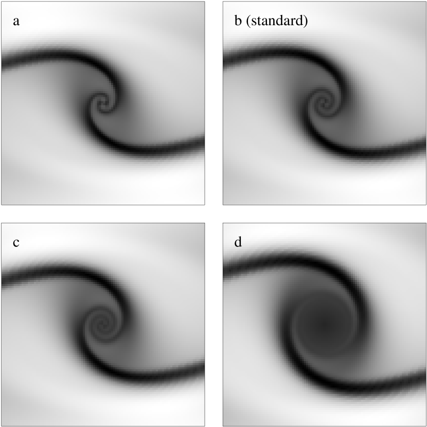
Fig. 5 reveals a strong dependence of the spiral shape in the nuclear region on . Most important, the winding is increased with . A factor of 2 in makes the spiral pattern so tightly wound that it is not recognizable any more beyond the initial winding of . The result is the formation of a featureless nuclear disk within the inner pc. For larger disks, corresponding to larger , the incoming shocks from the leading edges of the bar move away from the bar major axis. For decreasing , the spiral becomes less tightly wound and finally collapses towards the bar’s major axis. The reason for this behavior is that decreasing corresponds to decrease in the central mass concentration in the model and in the strength of the ILR. The modeled gas responds in a nonlinear fashion, staying on orbits inside the weak ILR. This effect was observed in numerical simulations (Englmaier & Shlosman 1999) and leads to the centered shocks on the major bar axis. The strength of this effect depends also on the sound speed in the gas (Englmaier & Gerhard 1997), and is discussed below.
Equation (4) predicts the shape of the spiral pattern in the non-self-gravitating gas (solid line in Fig. 5). The measured pitch angle of the modeled spiral is given by dots on the same figure. We observe a two-fold behavior for , i.e., from the ILR inwards is decreasing until the shock pattern winds the angle of (, indicated by an arrow in Fig. 5), and then starts to unwind. Remarkably, there is a sharp break in slope at this point. The inner part of curve is in agreement with Eq. (4). As we have noted above, the outer part of the curve describes the nonlinear gas response to the bar forcing. Fig. 5 demonstrates that the large-scale shock penetrates inside the ILR and perturbs the nuclear gas disk, launching the wave packets towards the center. Hence it is the large-scale shock which directly drives the nuclear spiral structure.
It is interesting that the measured pitch angle closely follows the theoretical curve within (Fig. 5). The latter was calculated based on the WKB approximation which requires , i.e., a tightly wound spiral. However, we observe that even for points at the correspondence is very good, and becomes better when resolution is increased (Fig. 7).
In Fig. 8 we show the azimuthal velocity component of the gas flow measured along the spiral arm. Inside the transition radius the azimuthal gas velocity is very close to the rotational velocity in the axisymmetric potential (dashed line). Somewhat further out, the tangential velocity shows a sharp drop, due to the non-circular motions in the gas which is in the process of settling on orbits. This figure demonstrates the observational significance of the transition radius, . Namely, it represents the outer radius of the nuclear disk where the gas is found on nearly circular orbits aligned with the minor axis of the bar. The deviation from the axisymmetric rotation curve is largest around the ILR radius. Furthermore, the bar-driven shocks reach the bar major axis again at . Beyond this radius, the gas follows nearly circular orbits.
Note, that with increasing , the nuclear spiral becomes progressively more tightly wound. Because of the finite resolution in the numerical code, we need up to 4 grid points to resolve the shock. This corresponds to minimum spiral inclination of about , below which the neighboring shocks remain unresolved. In such a case, local numerical viscosity is increased and the spiral waves are quickly damped out. This explains why Fig. 3 does not show a nuclear spiral propagating towards smaller . A similar effect can happen in a realistic disk, where the ‘shock’ width is given by the mean-free path of individual clouds in the clumpy ISM. Hence, there is physical significance to the transition radius, , where is reaching its minimum. Namely, a pitch angle that is too small at prevents the wave packet from propagating inwards without interaction with other packets. The transition radius , where the nuclear spiral starts propagating inwards, depends on and . For larger and smaller , the transition radius moves out, leaving room for a larger nuclear disk.
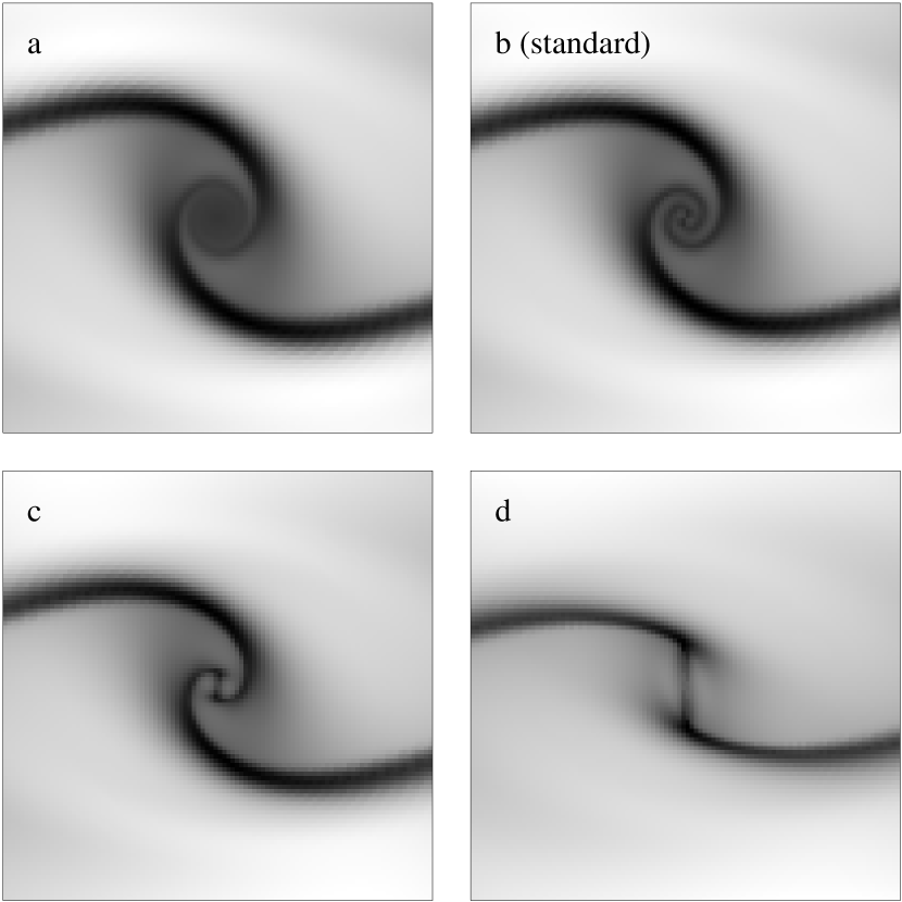
Varying the sound speed in the gas is another way of changing the strength of resonances, the ILR in this case. With increasing sound speed, the pitch angle becomes larger and the spiral pattern opens, until the shocks move closer to the bar major axis (Fig. 9). Eq. (4) predicts this trend due to the dependence of the wave number on the sound speed given by Eq. (2). On the large scale, this corresponds to shocks being only slightly offset from the bar major axis, as for low values of . Athanassoula (1992) observed this gas response of centered shocks when no ILR(s) were present in the model. Comparison of the theoretical pitch angle curve with models shows a nice correspondence between the two, and reveals a strong dependence of the minimum of on the sound speed. Already for the nuclear spiral is so tightly wound that the neighboring shocks become unresolved (see above). On the other hand, the nuclear pattern is very open already at .
The nuclear spirals can exist in a fairly narrow range of gravitational potential shapes and sound speeds. This range is expected to be typical of the conditions in the central kpc of disk galaxies. However, we cannot predict what fraction of disks actually will show this behavior. Partly, this is because a larger can be compensated by a larger , i.e., more centrally concentrated potential can correlate with larger sound speeds. A more detailed parameter search is necessary to decide how common nuclear spirals should be.
None of the models presented here show nuclear spirals extending to the center, i.e., they terminate at around pc. At these distances, the spiral pitch angle is about and the WKB theory is not reliable. We note that at such high , the wave packet will reach the center within less than a quarter of a turn, and the wavelength is , the distance to the center.
5 Discussion
We have presented a way to generate a grand-design spiral pattern in the central regions of barred galaxies. Such spirals have been reported recently by Laine et al. (1999) and Regan & Mulchaey (1999). For simplicity, we neglected the gas self-gravity and investigated the gas response to a background gravitational potential of a galactic disk with a large-scale stellar bar. The bar pattern speed and the shape of the gravitational potential were chosen so that only one ILR exists. We have found that in such a case, and within a wide range of parameters, the gas response extends from the corotation across the ILR into small radii ( pc), in a nice agreement between the theoretical and numerical morphologies. First, the strength of the gas response changes substantially at a transition radius, at a few hundred parsecs from the center. Namely, at larger radii, the gas displays a pair of strong bar shocks which curve around the ILR. At smaller radii, the shock amplitude is substantially reduced after first crossing of the bar major axis. Secondly, the pitch angle distribution shows a spectacular change in behavior at about the same radius. Outwards of this radius the shock pitch angle increases with radius, while for the innermost shocks the pitch angle decreases with radius, in accordance with the density wave theory. Based on the latter, we argue that the strong outer shocks perturb the gas inside the ILR, which populates weakly oval orbits along the bar minor axis. Short waves in the gas propagate radially inwards and are sheared by the disk rotation, producing weak shocks.
We have found that the nuclear spiral pattern depends on two parameters, i.e., the shape of the precession frequency and the sound speed in the gas. The former is directly related to the shape of the gravitational potential in the inner kpc of disk galaxies. The winding of the nuclear spirals inside the transition radius increases with a larger radial gradient in the potential, and hence with the larger central mass concentration. More centrally concentrated models show much weaker and more tightly wound spiral structure which eventually disappears due to the finite numerical resolution. In realistic disks, this limiting resolution corresponds to the finite width of the density wave, given by the mean-free path of molecular clouds. Damping of density waves results in a featureless nuclear gas disk. Decreasing the sound speed of the gas has a comparable effect on the nuclear spirals to that of increasing the central mass concentration. A higher sound speed creates a more open gas response.
Unfortunately, it is difficult to compare the numerical and theoretical shapes of nuclear spiral to the observed ones. Measuring the pitch angle in the - color index or in unsharp-masking images resulted in a large scatter (Laine, priv. comm). A detailed comparison with observations requires more high-quality data and is outside the scope of this paper.
Gas gravity should modify the amplitude of the gaseous response (e.g., Lubow, Cowie & Balbus 1986), but the basic results of Sections 2 and 4 are not expected to be grossly violated. Under certain conditions, the existence of the so-called -barrier (Bertin & Lin 1989) in a self-gravitating disk can damp both the short and long waves coming from larger radii to the center, and make the existence of nuclear spirals unlikely. In principle, it is possible to obtain a grand-design spiral pattern in a self-gravitating nuclear disk by generating it locally. In such a case the pattern speed of this structure will be gravitationally decoupled from the large-scale stellar bar and the accompanying large-scale gas response, as seen in numerical simulations (Heller & Shlosman 1994). However, no continuity between the inner and outer spirals is expected in this case, while at least some of the observations quoted above emphasize this feature. Flocculent multi-arm nuclear spirals have been detected also in disk galaxies which are not known to possess stellar bars. Those may be formed due to acoustic wave instabilities (Elmegreen et al. 1998).
The process discussed here emphasizes the driving (although indirectly!) of nuclear structure by a large-scale perturbation (stellar bar). This results in the equal pattern speeds for the nuclear spirals and the large-scale bar, in contrast to all other mechanisms. Given this, and to the extent that one can neglect the self-gravitational effects in the wave dispersion relationship (Eq. 1), detection of nuclear spiral structure limits the range of parameters, such as the rotation velocity and the sound speed. For example, in Eq. (4), observing , at some , and assuming a reasonable sound speed in the gas, will enable us to put limits on the bar pattern speed, , by Eq. (3).
A number of side effects can accompany the evolution of grand-design nuclear spirals. We mention only one such effect here. The characteristic timescale of radial propagation of wave packets across the nuclear disk (defined here as the area within the transition radius, ) is estimated to be about yrs. This timescale is much shorter than any timescale related to the large-scale galactic morphology (such as the stellar bar), but it is of the same order of magnitude as dynamical effects within roughly the central 500 pc. Those include the random walk of the center of mass of the nuclear disk with respect to the center of mass of the rest of the galaxy, or precession of an inclined nuclear disk around the galactic rotation axis. In fact, any perturbation in the center will evolve on this timescale.
It is interesting that the nuclear spiral pattern will respond to these perturbations slowly enough, so that the shape of the spirals will not be adjusted instantly. Such a pattern will be able to show visible distortions. The mere detection of the latter will tell us about the possible dynamical processes operating in the central regions of disk galaxies.
Appendix A The frozen potential beyond corotation
The frozen model potential beyond the corotation consists of three components, namely the bulge, the disk, and the halo. The bulge is described by a Plummer sphere
| (A1) |
where is the spherical radius, the scale radius , and mass . The Kuzmin-Toomre disk is given by
| (A2) |
in cylindrical coordinates , and with , and . Finally, for the halo we again chose a Plummer sphere with a scale radius of , and mass .
References
- (1) Athanassoula, E. 1992, MNRAS, 259, 345
- (2) Bertin, G. & Lin, C.C. 1989, Spiral Structure in Galaxies, MIT press, Cambridge, Massachusetts
- (3) Bertin, G., Lin, C.C., Lowe, S.A. & Thurstans, R.P. 1989, ApJ, 338, 104
- (4) Binney, J.J. & Tremaine, S. 1987, Galactic Dynamics, Princeton University Press, Princeton, New Jersey
- (5) Buta, R. & Combes, F. 1996, Fund. of Cosmic Phys., 17, 95
- (6) Carollo, C.M., Stiavelli, M. & Mack, J. 1998, AJ, 116, 68
- (7) Contopoulos, G. & Papayannopoulos, T. 1980, A&A, 92, 33
- (8) Cowie, L.L. 1980, ApJ, 236, 868
- (9) Devereux, N., Ford, H. & Jacoby, G. 1997, ApJ, 481, L71
- (10) Dopita, M. A., Koratkar, A.P., Allen, M.G., Tsvetanov, Z.I., Ford, H.C., Bicknell, G.V. & Sutherland, R.S. 1997, ApJ, 490, 202
- (11) Elmegreen, B.G. et al. 1998, ApJ, 503, 119L
- (12) Englmaier, P. & Gerhard, O. 1997, MNRAS, 287, 57
- (13) Englmaier, P. & Shlosman, I. 1999, in preparation
- (14) Ferrers, N.M. 1877, Q. J. Pure Appl. Math., 14, 1
- (15) Ford, H. C. et al. 1994, ApJ, 435, L27
- (16) Goldreich, P., & Tremaine, S. 1978, ApJ, 222, 850
- (17) Goldreich, P., & Tremaine, S. 1979, ApJ, 233, 857
- (18) Grillmair, C.J., Faber, S.M., Lauer, T.R., Hester, J.J., Lynds, C.R., O’Neil, E.J., Jr., Scowen, P.A. 1997, AJ, 113, 225
- (19) Heller, C.H. & Shlosman, I. 1994, ApJ, 424, 84
- (20) Heller, C.H. & Shlosman, I. 1996, ApJ, 471, 143
- (21) Knapen, J.H., Shlosman, I. & Peletier, R.F. 1999, ApJ, in press
- (22) Laine, S., Knapen, J.H., Perez-Ramirez, D., Doyon, R. & Nadeau, D. 1998, MNRAS, 302, 33L
- (23) Lin, C.C.& Shu, F.H. 1964, ApJ, 140, 646
- (24) Lubow, S.H., Cowie, L.L. & Balbus, S.A. 1986, ApJ, 309, 496
- (25) Mulder, W.A. 1986, A&A, 156, 354
- (26) Phillips, A.C., Illingworth, G.D., MacKenty, J.W. & Franx, M. 1996, AJ, 111, 1566
- (27) Prendergast, K.H. 1962, Distribution & Motion of ISM in Galaxies, ed. L. Woltjer, New York: Benjamin, 217
- (28) Regan, M.W. & Mulchaey, J.S. 1999, AJ, in press, astro-ph/9903053
- (29) Sanders, R.H. & Huntley, J.M. 1976, ApJ, 209, 53
- (30) Schwarz, M.P. 1984, MNRAS, 209, 93
- (31) Stone, J.M. & Norman, M.L. 1992a, ApJS, 80, 753
- (32) Stone, J.M. & Norman, M.L. 1992b, ApJS, 80, 791
- (33) Toomre, A. 1969, ApJ, 158, 899
- (34) Toomre, A. 1977, ARA&A, 15, 437
- (35) Toomre, A. 1981, The Structure and Evolution of Normal Galaxies, eds.: Fall, S.M. and Lynden-Bell, D. (Cambridge: Cambridge University Press), 111
- (36) van Albada, T.S., & Sanders, R.H. 1982, MNRAS, 201, 303
- (37) van Albada, T.S., & Roberts, W.W., Jr. 1981, ApJ, 246, 740
- (38) Whitham, G.B. 1974, Linear and Nonlinear Waves, New York: Wiley
- (39)


| Point | |||
|---|---|---|---|
| D | 0 | 0 | |
| B | |||
| C |