Abstract
We describe the VIRMOS Mask Manufacturing Unit (MMU) configuration, composed of two units: the Mask Manufacturing Machine (with its Control Unit) and the Mask Handling Unit (inclusive of Control Unit, Storage Cabinets and robot for loading of the Instrument Cabinets). For both VIMOS and NIRMOS instruments, on the basis of orders received by the Mask Preparation Software (see paper (a) in same proceedings), the function of the MMU is to perform an off-line mask cutting and identification, followed by mask storing and subsequent filling of the Instrument Cabinets (IC). We describe the characteristics of the LPKF laser cutting machine and the work done to support the choice of this equipment. We also describe the remaining of the hardware configuration and the Mask Handling Software.
1 INTRODUCTION
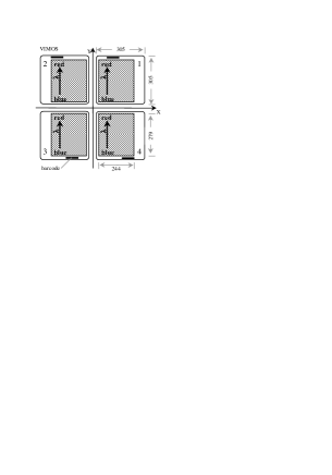
The Mask Manufacturing Unit (MMU) is dedicated to the off-line manufacturing, identification and preparation of the slit masks for both VIMOS and NIRMOS instruments. The MMU includes 2 sub-units: 1) the Mask Manufacturing Machine (MMM), dedicated to the machining of slits in thin sheets (masks) and 2) the Mask Handling System (MHS), dedicated to the handling of the masks, up to the loading into the Instrument Cabinets (IC). Fig 1 shows the VIMOS focal plane mask reference system.
2 MMU REQUIREMENTS
2.1 Masks
R1) - Roughness of the slit edges.
The VIRMOS Technical Specifications required 5 m peak to peak, regardless of the slit width.
This specification has been translated into the following quantities measurable by means of a mechanical
roughness meter equipped with a knife-type probe:
-
1.
max number of deviations from the mean 2.5 m in 1 cm: 2 (parameter Pc))
-
2.
r.m.s. as measured by the Rq parameter : 2 m
-
3.
profile shape as measured by the waviness parameter Wt : 3 m.
R2) - Time necessary to manufacture a mask.
The required cutting speed is 7 m/hr. This specification is given to the MMM manufacturer as:
5 mm/sec (18 m/hr) with a quality of the cut as specified above and 30 mm/sec (108 m/hr)
without maintaining the quality of the cut needed for the slits.
R3) - Global slit positioning accuracy.
The requirement is 30 m, including mask positioning at the focal plane and temperature variations
between fabrication and operation.
R4) - Unique and automatic mask identification.
Each mask must be uniquely identified for the time in which it can be used (until it is discarded).
R5) - Mask surfaces.
The masks surfaces must have the lowest possible reflectivity at the operating wavelengths.
2.2 Instrument Cabinets
R6) - Each instrument has 4 ICs (4 quadrants). Each IC can hold 15 masks and has a specific mechanical interface allowing it to be inserted in only one position on the instrument. The final design of the ICs is not yet defined at the time of writing. A remotely controlled device moves the masks from the ICs to the focal plane, and back.
2.3 Storage Cabinets
R7) - The manufactured mask must be temporarily stored in 2 Storage Cabinets (one for each instrument) waiting for the insertion in the ICs or for the discarding. Each SC is requested to contain 400 masks (100 mask-sets).
3 CHOICE OF THE CUTTING TECHNOLOGY
3.1 Short history
In the initial concept, the MMM was a milling machine which would cut the slits in a 0.1 mm thin brass sheet supported by an aluminium frame. We assembled a small milling machine with a 3 axes displacement system and a high speed mandrel (up to 80000 t/m). The minimum obtainable slit width was 300 m. Because of the frames, the ICs were large and quite heavy. Furthermore, the accuracy in the slit positioning was hampered by the composition of errors due to the machine positioning accuracy, the interface error between the mask frame and the machine working platform, and between the mask frame and the focal plane. Furthermore, because of the thermal expansion of brass it was difficult to meet the specification on positioning accuracy, given the temperature differences between the time a mask is manufactured and used in the instrument focal plane. Subsequent developments were aimed at minimising the sources of errors, by making use of thicker (but still 0.3 mm) Al unframed masks, reducing the size and the weight of the IC and eliminating the manpower necessary to open the frames, remove the brass sheet and put in a new one. The next natural step was the use of a material with a very low thermal expansion coefficient like carbon fibre, kevlar, graphite or Invar, but it was impossible to obtain the slit edge quality with the milling machine. It was only recently that a new type of laser cutting machines, called Stencil Lasers, became available on the market : these machines and one in particular were proven able to meet the specifications by making use of 0.2 mm thick Invar sheets. The cutting speed made possible to cut the mask contour on the machine itself, and thus it can be customised to the quadrant interface where the mask will be placed, and, as a further bonus, also any slits width 100 m became a possibility.
3.2 Milling vs laser cutting
For the milling technique the case of unframed aluminium masks has been considered for the comparison.
A summary is shown here.
Material
Milling: Aluminium (Anticorodal 100), thickness 0.3 mm, Therm.Exp.Coeff.: 23 /m/C.
Laser: Invar (Pernifer 36), thickness 0.2 mm, Therm.Exp.Coeff.: 0.8 m/m/C.
Coating
Milling: black anodization.
Laser: black antireflection paint.
Slit characteristics
Milling: Width : from 300 to 1000 m in steps of 100 m. Intermediate width require
two passes.
Laser: Width : any width 100 m.
Slit edge quality
Milling: The requested specifications can be reached but depend strongly on the material,
the diameter of the cutting tool, the cutting speed, the raw mask fixing system. The
optimisation and the control of these parameters is quite delicate over a long period of time. Quality
control of the slit edge must be done very frequently.
Laser: The requested specifications can be reached but depend on the manufacturers. Quality
control can be scheduled weekly.
Cutting of the mask contour
Milling: The mask contour cutting is difficult. Masks with pre-shaped contours are needed
(cannot be customised).
Laser: The mask contour can be cut to customise the mechanical interface of the masks to the
focal plane assembly.
Cutting machine components
Milling: The machine must be equipped with a high frequency mandrel, an automatic tool exchange
mechanism, a tool checking system, a working platform with lubricating liquid tank and a cleaning
unit to remove cutting oil.
We have not found Milling Machines that completely meet our requirements on the market. A customisation
is always necessary.
Laser: Laser machines meeting our requirements can be found on the market with integrated control
systems.
Mask production rate
Milling: about 15 minutes for the whole cycle. This performance is the lower limit of our test
machine and depends from the cutting tool diameter.
Laser: about 10 minutes including cutting the contour of the mask.
Purchase Cost
Milling: The estimated cost of the components for a home designed milling machine plus cleaning
unit is about 300 kDM. Engineering costs must be added.
Laser: The cost of a stencil laser cutting machine ranges from 530 (Lumonics) to 630 (LPKF) kDM.
3.3 Choice of the Laser cutting machine manufacturer
A statement of work has been sent to 22 laser cutting machine manufacturers. 11 companies answered our enquiry,
8 of which expressed their interest and 6 requested Invar samples to try out their product.
The most critical parameter to measure on test samples was the roughness of the slit edges. A first
qualitative evaluation has always been done using a microscope from 50 to 500 , to check whether
the slit cuts show a regular pattern (ripple) or a random noisy profile
the laser cutting has left some residual or re-melted material
the black coating has been damaged
the nominal slit width and shape has been respected
A quantitative evaluation of the profile roughness has been done using a mechanical roughness meter.
The results of the measures performed on the laser cutting samples provided by the manufacturers are
summarised in Table 1.
Tests from LPKF and Lumonics have been done with proprietary complete laser cutting machines, while
other manufacturers have used their laser head with unspecified motion systems.
Table 1 - Slit edge roughness measurements
| Manufacturer | Rq = rms (m) | Pc = number of p-p/cm 5m |
|---|---|---|
| LPKF | 0.8 | 1 |
| Lumonics (ripple-free zones) | 1.0 | 3 |
| Lumonics (ripple zones) | 1.8 | 15 |
| Rofin - Sinar | 2.6 | 33 |
| Haas | 2.5 | 40 |
| RTM | 4.0 | 30 |
| Required | 2 | 2 |
A high value of Pc means that the cutting edge has a residual ripple. In the table we report 2 rows for the Lumonics tests (about 50 cutting samples in 4 successive tests with different cutting parameters), since we noticed that the quality of the slit edges was not constant and that some areas with a quasi-sinusoidal ripple were almost always present. The effort done, together with Lumonics staff, to overcome the problem was not successful. This means that the Lumonics machine will need a tuning up of the cutting parameters to improve the performances which, so far, are critical with respect to the specifications. The only machine that completely fulfills our requirement was the LPKF, Garbsen, Germany, one.
4 THE ADOPTED SOLUTIONS
4.1 Mask material
The masks material is Invar with thickness 0.2 mm and dimensions 305 305 mm. The main mechanical and thermal characteristics of Invar (Krupp VDM trade name is Pernifer 36), at 20 C are listed in Table 2.
Table 2 - Invar characteristics
| chemical composition: | 36% Ni + 64% Fe |
|---|---|
| density: | 8.1 |
| modulus of elasticity: | 143 |
| thermal expansion coefficient: | 0.8 /C between 0 and 40 C |
4.2 Mask black coating
The mask manufacturing include, as the last operation, the cutting of the external border and thus the raw
Invar sheets must have bigger dimensions to allow for the mechanical fixing on the working platform of the laser
cutting machine. A 340 by 450 mm sheet is presently adopted. The raw masks must be:
coated with a black anti-reflection paint
cut to the proper size
protected against scratches
packed to be shipped to Paranal.
The requested characteristics for the coating are:
thickness 20 m
good adhesion to the metallic substrate
dull black color
uniformity of the coating over the 2 surfaces.
The mask yearly need for VIRMOS is about 2400. The aim of our work was to find a method to prepare a large
quantity of raw masks at the lowest cost.
The quotation of the 0.2 mm thick Invar (from Krupp) is approximately 25 DM/kg for quantities of at least 1000 kg.
A 340 450 Invar foil weighs 0.250 kg; from 1000 kg of material about 4000 masks can be obtained. The cost
of the material for a single mask is then about 6.3 DM.
The Invar material is delivered by Krupp in rolls with the requested width; the possible solutions to provide the
raw masks are to cut the strip in foils and to varnish them, or to varnish the strip before cutting. We have tested
both possibilities.
The second method is the cheapest one and has been tested using a strip of stainless steel 450 mm wide.
The process consists of:
chemical (alkaline bath) and mechanical (brushing) cleaning
coating of the two sides of the strip, using a roller system
warm curing of the varnish
insertion of a low adhesion plastic protective film
straightening to eliminate the roll curvature
cutting to the requested dimensions
piling of the raw masks on a transport pallet.
The performed test has produced about 600 raw masks with good results from the point of view of the quality and of
the adhesion of the coating, but the first and the last part of the strip must be discarded and the Invar cost for
a single mask becomes 7 DM. The cost of the whole coating process is about 6 DM per foil. So the total cost of a raw
mask is 13 DM.
4.3 Mask coding
The chosen solution for mask identification was the direct cutting of a 6 digit bar code on a border of the masks using the 2/5 interleaved code. It can be read by decoders during all the operations of the Mask Handling System.
4.4 The mask manufacturing machine
The technical characteristics of the LPKF StencilLaser System 600 x 600 that has been choosen as the most
appropriate for our purposes, can be found on the LPKF web site www.lpkf.de/laser_en/laser_en.htm .
5 THE MASK HANDLING SYSTEM
5.1 Current configuration
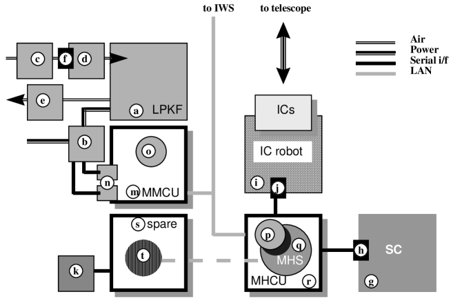
The overall hardware and software configuration of the MMU is depicted in the block diagram in Fig.2 and includes the
following components:
LPKF Stencil Laser machine model 600 x 600; ((a) in figure) with additional components supplied by LPKF
control electronics rack (b)
water cooling unit (c)
Maximator pressure duplicator from 8 to 16 bar (d)
vacuum extractor (e)
associated piping and cabling
dryer/filters (f) (additional element, not supplied by LPKF)
2 serial interface cards (n) hosted in MMCU computer
BoardMaster software (o) (running on MMCU)
CircuitCam software (p) (running on MHCU)
Mask Manufacturing Control Unit (MMCU) computer (m)
running LPKF BoardMaster software (o)
Storage Cabinets (SC, holding 4 100 masks) (g), built in house, with
Datalogic DS2100 bar code reader (h) connected to serial port of MHCU
IC robot unit (i), under development, with
Datalogic DS2100 bar code reader (j) connected to serial port of MHCU
hosting Instrument Cabinets (ICs) exchanged with the instrument focal plane ; each IC has 15 numbered mask slots
Mask Handling Control Unit (MHCU) computer (r)
running the Mask Handling Software (q) developed in house
with slaved LPKF CircuitCam software (p)
bar code support software
Taylor - Hobson Talysurf roughness meter (k)
with serial connection to spare computer
Spare computer (s)
with roughness meter acquisition software
with Microsoft Visual Basic development environment (t) used for MHS.
All computers are identical Dell model Optiplex GX1 under Windows NT 4.0 Workstation with 64 Mb RAM and
a 32 GB disk. They are configured in an identical way (with the exception of the serial card connections),
so that each one of them could be used as Line Replaceable Unit for all functions. In particular the spare computer
(currently used as development environment) will be kept in cold redundancy, and only occasionally used offline with
the roughness meter to perform quality checks on the manufactured masks.
The function of the Mask Handling Software developed in house and its interaction with the LPKF supplied software
modules will be described below.
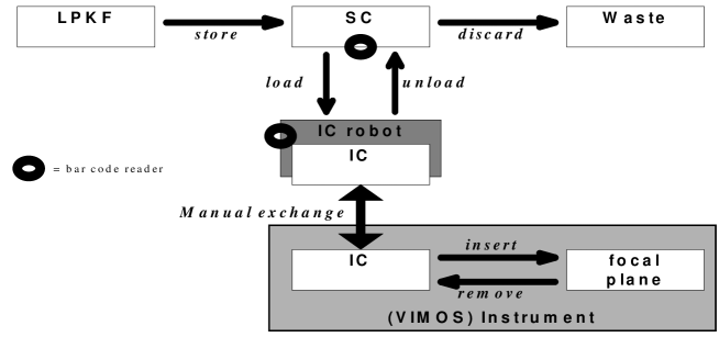
5.2 Mask movement scheme
The masks can be moved/relocated exclusively as shown in Figure 3. The movements between parts of the MMU system is controlled by the indicated MHS software functions (store, load, unload, discard). The movements inside the Instrument will be controlled by OS software functions. The exchange of entire ICs back and forth between Instrument and MMU buildings will be a manual operation.
5.3 Mask data files flow
Paper (a) describes the function of the VIMOS and NIRMOS Mask Preparation Software (MPS) as front end to
the MHS, and outlines the concept of Orders and Reports used to regulate the flow between OHS and MPS. There
is a one-to-one correspondence between such Orders and Reports (OHS-MPS layer) with Jobs and Termination
reports (MPS-MHS layer). For each Order sent by OHS to MPS, MPS sends a Job to MHS. MHS sends a Termination
report to MPS, which uses it to generate a Report to OHS.
Note that MPS is responsible to associate to each Observing Block (OB) a mask set, i.e. 4 masks identified by a unique
5 digit identifier. The 6-digit barcode is composed prepending a 1-digit quadrant identifier (1-4 for VIMOS and
5-8 for NIRMOS) to the mask code. MHS only knows about masks (sets), and knows nothing about OBs.
A Job is an ASCII file with a list of mask identifiers, and a Termination report is a similar ASCII file
associating an array of status codes to each mask. In addition to Jobs and Termination reports, there are other
types of files exchanged between MPS and MHS.
A series of Machine Slit Files (MSFs) generated by MPS and associated to a Mask Manufacturing Job.
They are described in paper (a)
Storage Cabinet Table files (SCT) are maintained by MHS and list all the masks currently stored in SCs.
Instrument Cabinet Table files (ICT) are maintained by MHS and list which masks are currently loaded in the
numbered slot of each IC.
The exchange of files between MPS and MHS occurs, for security reasons, exclusively via ftp sessions
initiated by the MPS side. MPS will put Jobs (and eventual MSFs) into an instrument staging area on MHCU.
MHS will move the files being processed and place back Termination reports and a copy of the ICT and SCT in the same area, from which MPS will get them.
Further file types are used internally in MHS as described below.
5.4 Description of the MMU cycles
In the following we describe the procedures used during the typical lifetime of a mask set required for spectroscopic observations. Different (simplified) procedures may apply to masks required for instrument maintenance.
5.4.1 Manufacturing and storage cycle
In response to a Mask Manufacturing Order sent from OHS to MPS, MPS translates it into a Mask Manufacturing
Job (MMJ) for MHS, and supplies an ASCII Machine Slit File (MSFs) for each mask
MHS convert function in turn:
converts all MSFs to the CAD industrial standard Gerber format
runs LPKF CircuitCam to convert Gerber files into proprietary binary format (LMD)
moves LMD files for entire mask sets to the MMCU disk.
Only complete mask sets (all four quadrant successfully converted) are considered for manufacturing.
Operator (on MMCU) uses the LPKF BoardMaster program to manufacture one mask at a time.
Masks are manufactured and stored 4 by 4 into an intermediate repository, to prevent storage of incomplete mask sets.
Operator (on MHCU) uses MHS store function to identify and store all masks of a mask set in the Storage Cabinet.
MHS store function updates the SCT (Storage Cabinet Table) and generates a Mask Manufacturing Termination report (MMT) for MPS.
MPS translates the MMT into a Mask Manufacturing Report for OHS.
5.4.2 Loading and unloading cycle
Some time later (at least one night in advance of the observation) OHS issues a Mask Insertion Order to MPS,
and MPS translates it into a Mask Insertion Job (MIJ) for MHS.
Instrument Cabinets (ICs) are physically moved from instrument to IC robot
Operator on MHCU runs MHS unload function, which arranges for any mask not in MIJ to be unloaded from IC
and put back in SC, while leaves in IC any mask already there and requested by MIJ.
Operator on MHCU runs MHS load function, which arranges to load from SC into IC any mask in MIJ not already
loaded and generates a Mask Insertion Termination report (MIT) for MPS. Both functions also update ICT and SCT
as appropriate
MPS translates the MIT into a Mask Insertion Report for OHS.
5.4.3 Discarding cycle
Some time later OHS issues a Mask Discard Order to MPS for OBs which have either been successfully executed
or have expired and MPS translates it into a Mask Discarding Job (MDJ) for MHS.
Operator on MHCU runs MHS discard function, which arranges for masks to be removed from SC and associated
LMD files to be deleted from MMCU (where they have been kept until this time to allow reproduction in case of
damages : this means that such masks cannot be manufactured again any longer) and generates a Mask Discard
Termination (MDT) report for MPS.
MPS translates the MIT into a Mask Discard Report for OHS: as a result the relevant OBs are marked as no longer
schedulable.