Data Acquisition System of the CANGAROO-II Telescope
M. Mori111 Institute for Cosmic Ray Research, University of Tokyo, Tanashi, Tokyo 188-8502, Japan, 2Department of Physics and Mathematical Physics, University of Adelaide, South Australia 5005, Australia, 3Institute of Space and Astronautical Science, Sagamihara, Kanagawa 229-8510, Japan, 4Department of Physics, Yamagata University, Yamagata 990-8560, Japan, 5Department of Physics, Tokyo Institute of Technology, Meguro, Tokyo 152-8551, Japan, 6Faculty of Management Information, Yamanashi Gakuin Univeristy, Kofu, Yamanashi 400-8575, Japan, 7Department of Physics, Tokai University, Hiratsuka, Kanagawa 259-1292, Japan, 8STE Laboratory, Nagoya University, Nagoya, Aichi 464-860, Japan, 9National Astronomical Observatory, Tokyo 181-8588, Japan, 10Faculty of Science, Ibaraki Univeristy, Mito, Ibaraki 310-8521, Japan, 11LPNHE, Ecole Polytechnique. Palaiseau CEDEX 91128, France, 12Institute of Physical and Chemical Research, Computational Science Laboratory, Institute of Physical and Chemical Research, Wako, Saitama 351-0198, Japan, 13Faculty of Engineering, Kanagawa University, Yokohama, Kanagawa 221-8686, Japan , S.A. Dazeley2, P.G. Edwards3, S. Gunji4, S. Hara5, T. Hara6, J. Jinbo7, A. Kawachi1, T. Kifune1, H. Kubo5, J. Kushida5, Y. Matsubara8, Y. Mizumoto9, M. Moriya5, H. Muraishi10, Y. Muraki8, T. Naito6, K. Nishijima7, J.R. Patterson2, M.D. Roberts1, G.P. Rowell1, T. Sako8,11, K. Sakurazawa5, Y. Sato1, R. Susukita12, T. Tamura13, T. Tanimori5, S. Yanagita10, T. Yoshida10, T. Yoshikoshi1, and A. Yuki8
Abstract
The data acquisition system for the new CANGAROO-II 7m telescope is described.
1 Introduction:
The CANGAROO-II 7m telescope which has just been completed in Woomera, Australia aims to extend our study of very-high-energy gamma-ray astrophysics to the hundreds GeV region.
The mechanical and optical design of the telescope are reported in Tanimori et al. 1999 and Kawachi et al. 1999, respectively: here we describe the data acquisition system.
2 Hardware:
2.1 Camera
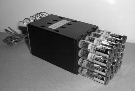
The prime focus of the reflector is equipped with a multi-pixel camera consisting of 512 fast photomultipliers (PMTs) of 13mm diameter with UV glass windows (Hamamatsu R4124UV) supplemented by light collecting cones which reduce the dead space between photosensitive area of the PMTs. A PMT base and amplifier module which houses 16 photomultipliers is shown in Figure 1. A total of 32 modules arranged in 66 square with the four “corner” modules missing make up the camera, which subtends a field-of-view of about 3 degrees. The signal from each PMT is fed into a preamplifier of gain next to the PMT base and is transmitted through twist-pair cables of 36m in length to the electronics modules located inside the electronics hut. The risetime of signals is about 5ns after the preamplifier and about 15ns after the twisted-pair cable.
2.2 High voltage
A high voltage power supply (LeCroy 1454/1461) gives a bias voltage to each PMT to obtain a rather low gain of in order to avoid possible overcurrent. The voltage is controlled and monitored via an RS232-C line by a host computer and adjusted and monitored. All 16 PMTs in the same base and amplifier module have the same high voltage, and so the PMTs for each module are carefully selected to ensure they have similar gains.
2.3 Signal processing electronics
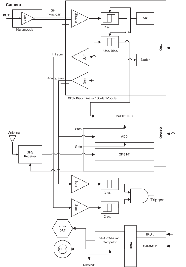
The block diagram is shown in Figure 2.
[2,r,![[Uncaptioned image]](/html/astro-ph/9906076/assets/x3.png) ,
An example of the pulse height vs. pulse width (or time over
threshold) curve. Sixteen curves from 16 PMTs assmbled in a module
(Figure 1) are shown.
These are measured in a laboratory with the same electronics and cables
using an LED light source.]
The discriminator and scaler module (DSM) works as a front-end
custom-made module based on the TKO specification (Ohska et al. 1985).
The signal from each PMT is shaped first and then fed into two discriminators:
a non-updating one to form event triggers and the other, an
updating one, to be sent to a multihit TDC (LeCroy 3377).
These discriminator levels can be adjusted on-line via the TKO bus.
Also included in this module are two summed outputs:
one is a linear sum of 16 input signals and the other is proportional
to the number of hit channels out of 16 in the module
(“hitsum”).
Two sets of these circuits are assembled in one board and make
up a 32 channel module.
,
An example of the pulse height vs. pulse width (or time over
threshold) curve. Sixteen curves from 16 PMTs assmbled in a module
(Figure 1) are shown.
These are measured in a laboratory with the same electronics and cables
using an LED light source.]
The discriminator and scaler module (DSM) works as a front-end
custom-made module based on the TKO specification (Ohska et al. 1985).
The signal from each PMT is shaped first and then fed into two discriminators:
a non-updating one to form event triggers and the other, an
updating one, to be sent to a multihit TDC (LeCroy 3377).
These discriminator levels can be adjusted on-line via the TKO bus.
Also included in this module are two summed outputs:
one is a linear sum of 16 input signals and the other is proportional
to the number of hit channels out of 16 in the module
(“hitsum”).
Two sets of these circuits are assembled in one board and make
up a 32 channel module.
The signal width, or time over threshold, measured with 0.5ns resolution in the TDC, gives information of the pulse height in a logarithmic way (Figure 3).
The linearly summed signal is sent to a CAMAC-based ADC (CAEN C205) and also used for event triggers. The former information supplements the signal amplitude in unit of the PMT base and amplifier module.
The 12-bit scalers in the DSM are activated for a short time (adjustable internally between 100s and 1ms) by an external trigger to provide a measure of the night sky background.
2.4 Trigger
Linear and hit-sums from 16 DSMs are summed in a linear adder module and fed into discriminators. An event is triggered when both of these summed signals become larger than preset values. This starts the data acquisition sequence via an interrupt register module on a CAMAC dataway.
2.5 Data readout
A VME-based board computer (FORCE CPU-7V, TurboSPARC 170MHz), running the Solaris 2.6 operating system and the UNIDAQ software (Nomachi et al. 1994), reads data from TDCs and an ADC through a VME/K-bus interface (Kinetic 2917) and a CAMAC crate controller (Kinetic 3922) upon receipt of a trigger. The multihit TDC records all leading and trailing edges of signals during 512ns with a double hit resolution of 10ns: this feature can also be used to cut and monitor the night sky background, since the time range is far larger than the Cherenkov light pulse duration.
Presently the system dead time is about 15% and 30% when the trigger rate is 12Hz and 28Hz, respectively.
PMT counting rates measured in the DSMs are read out with the 1 PPS (pulse per second) signals from a GPS time watcher (System Arts SA-870) and used to monitor bright stars.
Finally the data is stored on the local hard disk and is moved to a 4mm DAT after observation for off-line analysis.
2.6 Tracking
The alt-azimuth mount of the telescope is driven by a telescope controller based on a 68K processor board which accepts coordinates of the telescope in azimuth and elevation. The tracking computer calculates the designated coordinates and sends the values via an RS232-C line every 100ms. In parallel, encoder values are received. A real-time Linux (KURT) operating system has been adopted to achieve fast response time while retaining full Unix environment capability. The computer clock is synchronized to UTC utilizing the NTP software with a GPS receiver (Furuno TS-800) or world-wide time servers through dial-up internet connection in order to maintain tracking accuracy with errors less than 1 arcmin.
2.7 Calibration
At present we use a blue LED (Nichia Chemical) set at the center of the reflector and driven by a fast pulser as a light source for field-flattening of the camera. The use of laser pulses for faster timing is under consideration.
Relative event arrival times are measured with a CAMAC scaler counting 1 MHz clock pulses. The absolute timing of this clock is calibrated using the GPS time stamps encoded at a lower rate than the event trigger, due to the limited transferring rate of the GPS time receiver. This global timing system will be soon replaced by a faster VME-based GPS receiver module which gives time stamps to all events.
Telescope tracking accuracy was measured by observing stars at various elevations and azimuths with a CCD camera (SBIG ST-7) and a telescopic lens placed at the center of the reflector before installing the camera. The result shows the errors are well below 1 arcmin irrelevant to telescope positions, even at low elevations.
2.8 Monitor
Events are monitored in near real time, locally or via network, through an event display program utilizing the buffer managing capability of the UNIDAQ software. The voltages and currents supplied to PMTs are measured regularly and their values are logged. The sky condition is also monitored by a CCD camera (SBIG ST-5C) placed next to the camera and covering a similar field-of-view to the PMT camera.
The telescope tracking data, consisting of designated coordinates to the telescope controller and coordinates read from encoders, are regularly sent to the data-taking computer through network and recorded with the PMT data in order to ensure the telescope is pointing the expected direction.
3 Summary:
The data acquisition system for the CANGAROO-II 7m telescope has begun to collect data to investigate astrophysical gamma-rays in the several hundred-GeV region. We are planning to install ADCs to extend the dynamic range of observable gamma-ray energies. The data aquisition system for CANGAROO-III, an array of four 10m telescopes, will be designed with the experience gained during these developments.
References
Kawachi, A. et al., 1999, Proc. 26th ICRC (Salt Lake City, 1999).
Nomachi, M. et al.,, 1994, Proc. Int. Conf. on Computing in High Energy
Physics ’94, LBL-35822, pp. 114-116.
Ohska, T. K. et al., 1985, KEK Report 85-10 (KEK, Tsukuba, Japan).
Tanimori, T. et al., 1999, Proc. 26th ICRC (Salt Lake City, 1999).