An Optical Reflector for the CANGAROO-II Telescope
Akiko Kawachi111 Institute for Cosmic Ray Research, University of Tokyo, Tanashi, Tokyo 188-8502, Japan, 2Department of Physics, Tokyo Institute of Technology, Meguro, Tokyo 152-8551, Japan, 3Department of Physics and Mathematical Physics, University of Adelaide, South Australia 5005, Australia, 4Institute of Space and Astronautical Science, Sagamihara, Kanagawa 229-8510, Japan, 5Department of Physics, Yamagata University, Yamagata 990-8560, Japan, 6Faculty of Management Information, Yamanashi Gakuin University, Kofu, Yamanashi 400-8575, Japan, 7Department of Physics, Tokai University, Hiratsuka, Kanagawa 259-1292, Japan, 8STE Laboratory, Nagoya University, Nagoya, Aichi 464-860, Japan, 9National Astronomical Observatory, Tokyo 181-8588, Japan, 10Faculty of Science, Ibaraki University, Mito, Ibaraki 310-8521, Japan, 11LPNHE, Ecole Polytechnique. Palaiseau CEDEX 91128, France, 12Computational Science Laboratory, Institute of Physical and Chemical Research, Wako, Saitama 351-0198, Japan, and 13Faculty of Engineering, Kanagawa University, Yokohama, Kanagawa 221-8686, Japan , J. Kushida2, S.A. Dazeley3, P.G. Edwards4, S. Gunji5, S. Hara2, T. Hara6, J. Jinbo7, T. Kifune1, H. Kubo2, Y. Matsubara8, Y. Mizumoto9, M. Mori1, M. Moriya2, H. Muraishi10, Y. Muraki8, T. Naito6, K. Nishijima7, J.R. Patterson3, M.D. Roberts1, G.P. Rowell1, T. Sako8,11, K. Sakurazawa2, Y. Sato1, R. Susukita12, T. Tamura13, T. Tanimori2, S. Yanagita10, T. Yoshida10, T. Yoshikoshi1, and A. Yuki8
Abstract
We have been successful in developing light and durable mirrors made of CFRP (Carbon Fiber Reinforced Plastic) laminates for the reflector of the new CANGAROO-II 7 m telescope. The reflector has a parabolic shape (F/1.1) with a 30 m2 effective area which consists of 60 small spherical mirrors of CFRP laminates. The orientation of each mirror can be remotely adjusted by stepping motors. After the first adjustment work, the reflector offers a point image of about 0.∘14 (FWHM) on the optic axis.
1 Introduction
The CANGAROO team has just commenced operation of a new imaging Cherenkov telescope of 7 m reflector for observation of very high energy gamma-rays. With an effective collecting area of 30 m2, about three times as large as the CANGAROO-I telescope of 3.8 m diameter reflector, the new telescope aims at the detection of several hundreds GeV gamma-rays. The total design of the telescope is reported elsewhere (Tanimori et al. 1999), here we report the characteristics of its reflector.
2 Mechanical Design
A whole view of the reflector is shown in Figure 1. The reflector is an F/1.1 paraboloid with a diameter of 7.2 m. In order to use timing information to reject night sky background, we chose a parabolic shape where the dispersion of photon arrival times caused by different light paths in the mirror is small.
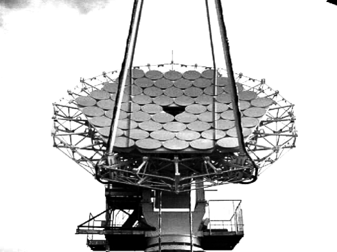
Sixty spherical mirrors, each of which has an 80 cm diameter and a curvature radius between 16–17 m, were arranged according to their curvature radii from the inner to the outer sections of the reflector, with the shorter focal length mirrors innermost. In the prime focal plane, there is a multi-pixel camera with 0.∘12 pitch covering about 3 degrees of FOV (Tanimori et al. 1999, Mori et al. 1999).
The supporting frame of the reflector mounted by 9 honeycomb panels is rather light in weight to save cost and assembling labor. Several mirrors (6–9) were installed onto a honeycomb panel and the alignment of the mirrors in each panel was roughly adjusted with a laser beam before the shipping to Australia. With these adjustments, we checked our remote adjustment system as well as it saved on-site labor described in Section 4.
The structure was designed to be sustained at the average velocity 30 km/hr of the wind load, and gravitational deformations were measured to cause as small as 1 of deviation at the focal plane. The present support frame allows us to extend the reflector up to 10 m diameter with additional 54 mirrors, and the extension is to be completed by the beginning of 2000.
3 Small Spherical Mirror
The small spherical mirrors are of 80 cm in diameter and weigh only about 5.5 kg. Sheets of CFRP and adhesives were laid on a metal mold, sandwiching a core of low density, high shear strength foam () to avoid twisting deformations, and a polymer sheet coated with laminated aluminum was applied on the top of the layers as a reflecting material. The laminates were vacuum bagged and cured in an autoclave pressure vessel.
We examined possible deterioration by repeating 200 cycles of rather extreme changes in temperatures of 0∘–50∘C. Change in the curvature was found to be negligible after the examination.
For protection against dust, rain, and sunshine, the mirror surface was coated with fluoride. The coat maintains more than 80 % reflectivity down to 300 nm, corresponding both to the atmospheric transmission cut-off at 300 nm of Cherenkov light, and to the spectrum response
of the PMT photo-cathode with UV-transparent window (Hamamatsu, R4124UV). It was confirmed in a year-time-scale that the reflectivity repeatedly recovers easily by washing.
The curvature radii of the mirrors was found to distribute between 15.9–17.1 m, with an average of 16.45 m. The mirrors were arranged on the support according to their radii to make a smooth =8 m paraboloid, and the individual facets were adjusted toward the focal point by the method described later. The image size of each mirror was measured with a light source 5.8 km away. A typical size is 0.∘08 (FWHM), and 50 % of the photons concentrates within 0.∘1 . Including some mirrors of moderate image size, the average of focusing properties of the 60 mirrors is about 0.∘1 (FWHM).
4 Remote Adjustment of the Alignments
Two watertight stepping motors are installed at the back surface of each mirror, and the orientation of a mirror can be remotely adjusted in two perpendicular directions. The minimum step size corresponds to about 1 degree at the focal plane, and 3-degree adjustment is possible. The accuracy of 1 degree is retained when motors are switched off. All mirrors are adjusted one by one using two motor drivers with relay switches controlled by a computer.
After the mechanical assembly of the telescope, we adjusted the orientations of the mirrors on-site using a point light source at 5.8 km distant at night. The telescope was precisely pointed at the direction of the light source determined by a survey. All small mirrors were covered but one, and its image on a screen at the focal plane was monitored by a CCD camera installed at the center of the reflector. The orientations of the mirrors were adjusted by moving stepping motors using feedback information from CCD images, so that the image center should lay at the focal point.
As a result of the first adjustment work, the deviation of the small mirror axis orientations is 0∘.03 0∘.01 (statistical error only) on average, a larger value than expected. The deviation was mainly caused by temporal fluctuations of the CCD camera geometry over different nights we applied the adjustment, leading to deviations of the focal point on the screen. Removing this effect, it is estimated that the orientations can be adjusted within an error of 0∘.01.
5 Star Image, On and Off Axis
[1,r,![[Uncaptioned image]](/html/astro-ph/9906075/assets/x2.png) ,
A CCD image of Canopus on the optic axis. The axes are in unit of CCD pixels,
corresponding to a 6.710-3 degree pitch.
axis is in arbitrary unit. A square overdrawn is a scale of
a pitch of the camera (0∘.12 square).]
The focusing property of the reflector in total was measured using images of
several stars tracked by the telescope.
Images on the focal plane screen were taken by a CCD camera at the reflector
center.
,
A CCD image of Canopus on the optic axis. The axes are in unit of CCD pixels,
corresponding to a 6.710-3 degree pitch.
axis is in arbitrary unit. A square overdrawn is a scale of
a pitch of the camera (0∘.12 square).]
The focusing property of the reflector in total was measured using images of
several stars tracked by the telescope.
Images on the focal plane screen were taken by a CCD camera at the reflector
center.
In Figure 2, an image of Canopus on the optic axis is shown in units of CCD pixels. A pixel corresponds to 6.710-3 degree. One pixel of the camera (0∘.12 square) is overdrawn for scaling. A point spread function is also shown in Figure 3 (a). An image size of 0∘.140∘.01 (FWHM) is deduced, and 304 % of the photons concentrates in a single camera pixel. The image concentration is only 60 % of the expected value in design, and this dispersion might be mainly due to our on-site adjustment of the mirror-orientations.
When incident rays are not parallel to the optic axis of the reflector, the overall shape of the composite reflector causes aberrations. Among them, the effect of coma aberration is dominant for a parabolic mirror and other aberrations of each facet mirror can be neglected. The aberration is rather serious for a Cherenkov imaging telescope since a relatively wide field of view (3∘) is needed for image analyses of atmospheric showers.

We compared off-axis images of Sirius displacing the pointing coordinates by 1.3 degree both in right ascension and in declination. As a result of symmetric configuration and alignments, displacement to all the directions caused deformations consistent with each other.
Figure 3 shows radial point spread functions of the star pointed on and 1.25 degrees off the optic axis. An effect of aberrations arise at 0.∘07 distant from the peak center (the half-width of a camera pixel is 0.∘06), thus FWHMs of the on and off-axis images (about 0.∘14) are equal. Measurements of the concentration, however, differ by about 18 % at the edge of FOV.
The effect of gravitational deformations on the reflector was measured by comparing the images of stars taken at various elevation angles of the telescope. For elevation angles between 15–70 degrees, the images show no dependence on the elevations either in shape or in size. Thus the deformations are confirmed to be negligible.
6 Summary:
The new CANGAROO-II 7 m telescope has been completed and operations has begun. The reflector, F/1.1 paraboloid, has a point spread function of 0.∘14 (FWHM) over 3 degrees of FOV, with 18 % loss of light by aberration at the FOV edge. About 30% of the optical light detected from an on-axis point source falls in a single camera pixel.
7 Acknowledgments
The small mirrors of CFRP laminates have been developed in collaboration with Mitsubishi Electric Corporation, Communication Systems Center.
References
Mori, M. et al., 1999, Proc. 26th ICRC (Salt Lake City, 1999)
Tanimori, T. et al., 1999, Proc. 26th ICRC (Salt Lake City, 1999)