The twisted parsec-scale structure of 0735+178
Abstract
We present two epoch polarimetric images of the BL Lac object 0735+178 obtained with the Very Long Baseline Array at 22 and 43 GHz. These images provide the highest resolution observations of this source to date, and show a twisted jet with two sharp apparent bends of 90∘ within two milliarcseconds of the core. The magnetic field appears to smoothly follow one of the bends in the jet, suggesting that this structure may be the result of a precessing nozzle in the jet of 0735+178. Proper motion information is not conclusive as to whether the twisted geometry is the result of knots moving ballistically or following the direction of the jet axis.
Subject headings:
Polarization - Techniques: interferometric - galaxies: active - BL Lacertae objects: individual: 0735+178 - Galaxies: jets - Radio continuum: galaxies1. Introduction
0735+178 was first classified as a BL Lacertae object by Carswell et al. (carswell 74 (1974)), who identified a pair of absorption lines in an otherwise featureless optical spectrum, thereby obtaining a lower limit to the redshift of the source . Hence, any observed apparent speeds in 0735+178 calculated using this redshift are strictly lower limits.
Radio maps of this source at milliarcsecond resolution have been obtained by using VLBI arrays at centimeter wavelengths, and show a compact core and a jet of emission extending to the northeast. Polarimetric VLBI observations of this source were first performed by Gabuzda, Wardle & Roberts (De89 (1989)) at a wavelength of 6 cm: the corresponding polarized intensity image shows a jet magnetic field that is predominantly perpendicular to the jet axis, together with a dramatic change in the polarized flux by 40% over a period of 24 hours. The multi-epoch 6 cm VLBI observations of 0735+178 presented by Bääth & Zhang (BZ91 (1991)) indicated superluminal motion in their component C0 at an apparent velocity of 7.9 (= 100 km s-1Mpc-1, = 0.5), moving between the core and a stationary component, which they labeled B, situated about 4.2 mas from the core. This situation resembles that found in the quasar 4C 39.25 (Alberdi et al. An93 (1993) and references therein), where a very strong component moves superluminally between the core and an outer stationary component, and its increasing brightness as it moves is interpreted as Doppler enhancement caused by a bend toward the line of sight. Gabuzda et al. (1994a ; hereafter G94) confirmed the motion of the superluminal component C0, which they designated as K2, at a velocity of 7.4 , and detected two new superluminal components with apparent transverse speeds of 5.0 and 4.2 . The observations of G94 were near the time of intersection of the moving component K2 with the stationary one K1 (component B of Bääth & Zhang BZ91 (1991)), which took place at epoch 1989.8. Their images do not show any evidence for a violent interaction between these components, and they interpret this in terms of a model similar to that suggested by Bääth & Zhang (BZ91 (1991)), in which the stationary component K1 is associated with a bend in the jet toward the line of sight. However, if this is the case, we might expect a deceleration of K2 as it approaches K1, along with an increase of its flux due to enhancement of Doppler boosting, as observed and simulated in the case of 4C 39.25 (Alberdi et al. An93 (1993)). Neither of these were observed in 0735+178. If K1 corresponds to a bend toward the observer, it also remains unclear why G94 measured component K1 to have shifted 0.7 mas outward sometime between 1981.9 and 1983.5, after its collision with K2, and to have remained in that position afterward. One explanation for this “dragging” of K1 is that we are dealing with an interaction between a moving shock (K2) and a standing conical shock (K1), as Gómez et al. (Go97 (1997)) have modeled through numerical simulations. In this scenario, an increase in the Mach number of the flow causes the stationary shock to reset to a new site downstream of its original position.
Higher resolution VLBI maps obtained by Bääth et al. (Bal91 (1991)) at 1.3 cm reveal a complex structure consisting of several distinct superluminal components moving in a rather straight jet extending to the northeast. However, a fit to the kinematical properties of the superluminal components led Bääth et al. (Bal91 (1991)) to suggest a bend of the jet in the inner milliarcsecond. Indeed, a quite complex structure in the inner milliarcsecond of 0735+178 appears in the 1.3 cm VLBI maps presented by Zhang & Bääth (ZB91 (1991)). Over a time span of about 1.2 yrs, the jet structural position angle was found to change from 25∘ to 73∘. It is unclear whether Zhang & Bääth (ZB91 (1991)) observed different components tracing a bent common path, or components being ejected from the core with different position angles, as G94 suggested based on their observations. The first direct evidence of a curved structure in the inner jet of 0735+178 was presented by Kellermann et al. (Ke98 (1998)), as part of a Very Long Baseline Array survey (VLBA111 The VLBA is an instrument of the National Radio Astronomy Observatory, which is a facility of the National Science Foundation operated under cooperative agreement by Associated Universities, Inc. ) at 15 GHz.
In this paper we present the first polarimetric VLBI observations of 0735+178 at 1.3 cm and 7 mm, obtained with the VLBA. The images show an apparently quite twisted structure in the inner two milliarcseconds of the jet, in very good agreement with the total intensity 2 cm VLBA image obtained by Kellermann et al. (Ke98 (1998)). We analyze and interpret the magnetic field struture and jet morphology, and discuss the possibility of a precessing jet in 0735+178.
2. Observations
The observations were performed on 1996 November 11 and December 22 using the VLBA at 1.3 cm and 7 mm in snapshot mode. The data were recorded in 1-bit sampling VLBA format with 32 MHz bandwidth per circular polarization. The reduction of the data was performed within the NRAO Astronomical Image Processing System (AIPS) software in the usual manner (e.g., Leppänen et al. Le95 (1995)). Delay differences between the right- and left-handed systems were estimated over a short scan of cross-polarized data of a strong calibrator (3C 454.3). The instrumental polarization was determined using the feed solution algorithm developed by Leppänen et al. (Le95 (1995)). We refer the readers to Gómez et al. (Go98 (1998)) for further details about the reduction and calibration of the data.
Due to poor weather conditions in some of the antenna locations during the second run, specially at Brewster, much of the 7 mm data had to be deleted, leading to a significantly poorer total intensity image and the loss of all polarization at this epoch.
3. Results
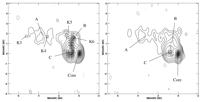
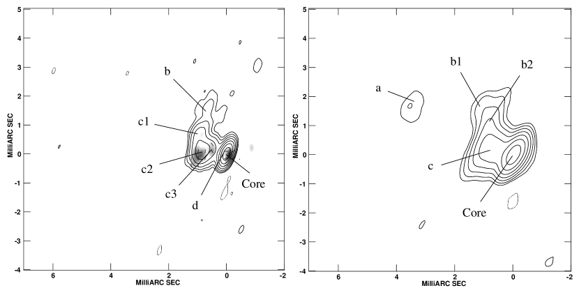
Figures 1 and 2 show the VLBA total and linearly polarized intensity images of 0735+178 at 1.3 cm and 7 mm, respectively. Tables 1 and 2 summarize the physical parameters obtained for 0735+178 at 1.3 cm and 7 mm, respectively. Tabulated data corresponds to position in right ascension and declination relative to the core component, total flux, polarized flux, magnetic field position angle, degree of polarization, and separation and structural position angle relative to the core component. Components in the total intensity maps were analyzed by model-fitting the uv data with circular Gaussian components using the Difmap software (Shepherd sh97 (1997)). Components are labeled from east to west using upper-case letters for the images at 1.3 cm, and are marked in Figs. 1 and 2. Due to the potentially large uncertainties associated with the process of model-fitting, only components well above the noise level were considered. For example, there is some weak evidence for the existence of components d and c1 in the 1.3 cm maps, but the errors in the model-fitting are sufficiently large that we have decided not to include these in the final model. Component B is best fit at the second 7 mm epoch by two separate components labeled b2 and b1, the combined flux of which compares quite well with that of component b in the 7 mm image at the first epoch. To reduce the errors in the model-fitting we have fit the emission from the section of the jet beyond component B as a single component, labeled A.
3.1. The Twisted Structure of the Inner Jet of 0735+178
Bääth et al. (Bal91 (1991)) and Bääth & Zhang (BZ91 (1991)) suggested the existence of bent structure in the jet of 0735+178 in order to explain the apparent acceleration of superluminal components as they moved further from the core. G94 found that components seem to move along linear trajectories, but to be ejected with different position angles, which could lead to apparent curved structure in the VLBI jet.
| Component | (mas) | (mas) | (mJy) | (mJy) | (∘) | (%) | (mas) | (∘) |
|---|---|---|---|---|---|---|---|---|
| 1996.86 | ||||||||
| Core | … | … | 354 | 7 | 86 | 2 | … | … |
| C | 0.81 | 0.19 | 361 | 12 | -12 | 3 | 0.83 | 77 |
| B | 0.7 | 1.3 | 87 | 9 | 31 | 10 | 1.5 | 29 |
| A | 3.6 | 1.8 | 37 | … | … | … | 4.1 | 63 |
| 1996.98 | ||||||||
| Core | … | … | 340 | 13 | 72 | 4 | … | … |
| C | 0.82 | 0.18 | 304 | 9 | -21 | 3 | 0.84 | 78 |
| B | 0.6 | 1.2 | 94 | 3 | 36 | 3 | 1.3 | 29 |
| A | 3.2 | 1.8 | 39 | … | … | … | 3.7 | 61 |
Our observations directly confirm the existence of a very twisted structure in the inner region of the jet in 0735+178, in good agreement with the observations presented by Kellermann et al. (Ke98 (1998)). In our 1.3 cm maps we observe two sharp 90∘ bends in the projected trajectory of the jet, one near the position of component C and the other close to B. At 7 mm the bend near the region of component c2 (component C at 1.3 cm) is also quite evident, while the second bend can only be traced at the second epoch, since the emission beyond component b is resolved out in November 1996.
Through a comparison with our maps, we can offer an explanation for the otherwise puzzling structure Zhang & Bääth (ZB91 (1991)) observed in their 1.3 cm VLBI maps. It is possible that they observed distinct components at different positions of a common curved path, consistent with that traced in our images. However in the 1.3 cm VLBI map by Bääth et al. (Bal91 (1991)) they observed in the inner milliarcsecond a straight jet extending northeast at a position angle of 45∘, in contrast with the structure we observe in our images. Furthermore, G94 measured different ejection position angles for components in 0735+178.
In order to allow an easier comparison with our images, we have marked in our November 1996 map of Fig. 1 the expected position for components K3, K4, K5, and K6 of G94 using their measured proper motions and assuming ballistic trajectories from the core since their last observing epoch in 1992.44. For component K5 we have used the position reported for their 1990.47 epoch, otherwise the extrapolation would place this component far too east of C, outside of the structure we have mapped. No proper motion data is available for component K6, but assuming a similar value to that observed for the other components, we have used 0.3 mas yr-1. Figure 1 shows that this extrapolation places the G94 components within the structure found on our images, suggesting ballistic motion with systematically changing component ejection directions as the most plausible explanation for the curved structure of 0735+178.
However, the data is also consistent with motion of components following a common curved path. Component K3 was observed to change drastically its position angle relative to the core between 1987.41 and 1990.47, from 75∘ to 44∘ (see G94). Component K5 also experienced a change in its position angle between 1990.47 and 1992.44, with its velocity vector becoming more aligned toward the direction of component C, between the position of components c3 and c2. The positions of components G94 in the inner milliarcsecond are consistent with the twisted structure we have mapped, therefore we cannot rule out the possibility of a common curved funnel through which components flow. Note also that this curved funnel could change with time if it were produced by precession of the nozzle in 0735+178. In the case of ballistic motion, the direction of ejection of new components should have changed progressively from 54∘, to 35∘, and then to 15∘ from 1984 to 1991.25 to explain the different structural position angles observed for the birth of K4, K5, and K6. The direction of ejection would then have needed to change to 78∘ within about 4 yr, if we assume that component C was ejected around the beginning of 1995, coincident with an outburst in total flux at 22 and 37 GHz measured at Metsähovi (Teräsranta et al. Hi98 (1998)). Since then, it would have had to remain at a similar orientation (at least on the plane of the sky) to give birth to components c3 and d, which according to two small flares in the Metsähovi data (Harri Teräsranta, private communication) took place around 1995.8 and 1996.7 (just before our first epoch), respectively. Note that the apparently curved jet of 0735+178 would appear more pronounced if components are ejected with different speeds, as seems to be the case.
Because of the short time range between our two epochs, the differences in the positions of the components lie within the errors in the model-fitting, therefore we can only rely on the observed magnetic field structure, and previous detections of components motions, to study the possibility of ballistic motions for the components in 0735+178.
3.2. Polarization
The peak polarization at both epochs and wavelengths is located at the core, with a degree of polarization between 2 and 4%, very close to the values measured by Gabuzda, Wardle, & Roberts (De89 (1989)) and G94 at 6 and 3.6 cm. However, these values should be regarded as approximate, since maxima in the images of polarized intensity are not always precisely coincident with maxima in the total intensity (see also Gómez et al. Go98 (1998)). Greater differences between the peaks in total and polarized intensity are found in the 7 mm map. Some polarized emission is also visible further from the core, especially at the first epoch at 1.3 cm. In this map the jet between components C and B can be traced in polarization, where it has a rather uniform intensity. For the second epoch at 1.3 cm the core and component C are clearly detected in polarization, and there is also weaker polarized flux detected at the position of B. In the 7 mm polarization map the core and component c2 are clearly visible. Another component appears close to the core, and we have tentatively identified this component as the polarized counterpart of d. Component c3 is also observed in polarization, while c1 is just marginally detected.
A very similar orientation of the magnetic field vector in the jet is observed at both epochs in the 1.3 cm maps and in the 7 mm map at November 1996. The magnetic field in the core at our first epoch is oriented toward the east, in the direction of component C. This is consistent with the values found by Gabuzda, Wardle, & Roberts (De89 (1989)), although opacity effects due to the different wavelengths of observation may render this comparison meaningless. If the core is optically thick at both wavelengths, we should consider an extra rotation of 90∘ in the polarization angle when comparing to the remaining optically thin jet. At epoch November 1996, adding the flux of the core and component d at 7 mm, we obtain a very similar value (the same to within the uncertainty) as that measured for the core at 1.3 cm. The same is true for the second epoch. The core polarization angle in the 7 mm map shows a slightly different value than at 1.3 cm, while component d shows a magnetic field more aligned with the jet. These differences between the 1.3 cm and 7 mm maps are probably due to differences in resolution, although they may reflect a change in the opacity of the core. G94 found a rotation of the polarization angle in the core when observed at different epochs and frequencies. These changes in the polarization angle may be due to ejections of new components with polarization angles different than the core. Because of the lower resolution, these may appear in their maps as variations of a single blended component -their core- similar to what we have experienced when comparing our 1.3 cm and 7 mm maps.
| Component | (mas) | (mas) | (mJy) | (mJy) | (∘) | (%) | (mas) | (∘) |
|---|---|---|---|---|---|---|---|---|
| 1996.86 | ||||||||
| Core | … | … | 241 | 7 | 116 | 3 | … | … |
| d | 0.10 | 0.02 | 98 | 2 | 84 | 2 | 0.10 | 80 |
| c3 | 0.46 | 0.11 | 26 | 4 | 29 | 15 | 0.47 | 76 |
| c2 | 0.87 | 0.09 | 189 | 10 | -6 | 5 | 0.87 | 84 |
| c1 | 0.96 | 0.66 | 62 | 2 | 26 | 3 | 1.16 | 56 |
| b | 0.7 | 1.5 | 48 | … | … | … | 1.7 | 24 |
| 1996.98 | ||||||||
| Core | … | … | 370 | … | … | … | … | … |
| c | 0.78 | 0.18 | 229 | … | … | … | 0.80 | 77 |
| b2 | 0.8 | 1.2 | 23 | … | … | … | 1.4 | 34 |
| b1 | 1.1 | 1.7 | 23 | … | … | … | 2.0 | 33 |
| a | 3.4 | 1.9 | 13 | … | … | … | 3.9 | 61 |
The magnetic field structure in the jet between C and B is complex, and difficult to interpret unambiguously. One obvious possibility is that the magnetic field follows the direction of the apparently twisted jet flow. In this case, the magnetic field throughout this part of the jet would be longitudinal. However, another interpretation is possible: that different features move from the core in different structural position angles, and that the magnetic field vectors are transverse to the flow direction in C and along the flow direction from the core in B. This alternative point of view is also consistent with the fact the magnetic field in component c3 also points back toward the core. In either of these interpretations the magnetic field in the jet north of C is longitudinal.
4. Theoretical Interpretations and Conclusions
Although 0735+178 represents the most abruptly bent jet observed at milliarcseconds scales to our knowledge, many jets in BL Lacs and quasars appear to be curved. While this is amplified by projection effects, since relativistic jets in blazars must be pointing close to the line of sight to explain superluminal motion and related phenomena, it is not clear what causes the bends of at least 5∘ that must be present to account for the observed twists.
One idea (Hardee Ha87 (1987)), which has supporting observational evidence (Denn & Mutel DM98 (1998)), is that the jet precesses, with the velocity vectors of the flow following the bends in the jet axis. Numerical three-dimensional magnetohydrodynamical simulations (Hardee, Clarke, & Rosen Ha97 (1997)) show how Kelvin-Helmholtz (K-H) helical instabilities can develop from an initial induced precession at the jet inlet, resulting in a twisted jet with a helical geometry and magnetic field configuration. Such K-H instabilities can also arise from an external pressure gradient not aligned with the initial direction of the jet flow.
Another possibility for jet bending is ballistic precession, such that the flow velocity is directed radially away from the jet apex, in the manner of SS 433; this may be suggested by the trajectories of components K3, K4, K5, and K6 (G94). Alternatively, the nozzle of the jet could change direction in a more erratic fashion than for precession. Bends can also occur in response to gradients in the pressure of the external medium that confines the jet. Another possibility, also suggested for 0735+178 by G94, is that components only illuminate part of a broad jet funnel, giving the illusion of a bent trajectory.
Each possibility for jet bending results in specific predictions. For example, in the case of erratic change in the nozzle direction, knots should separate from the core following ballistic trajectories. For ballistic precession of the nozzle, the different sections of the jet should connect smoothly and the magnetic field direction should relate to the radius vector from the core, rather than follow the jet curvature. For precession in which the flow velocity vector changes direction with the jet axis, moving components should follow the bends, as should the magnetic field vector. In addition, the flux density and apparent velocity of the components should change as the angle between the velocity and the line of sight vary, as in 4C 39.25 (Alberdi et al. An93 (1993)). A precessing jet can be distinguished from one that changes because of external pressure gradients by the regular pattern of the bend, which should follow the geometry of a helix in projection.
With only 41 days between our two epochs, the expected motions of the components in the jet of 0735+178 lie within the errors in our model-fitting, hence we cannot yet conclude whether components on these scales follow ballistic trajectories or the direction of the jet axis. A ballistic extrapolation of the position of the components observed in G94 shows that ballistic motions could explain the observed twisted structure for the jet. The information provided by the direction of the magnetic field, which follows the bend near component B, suggests that the jet in 0735+178 precesses such that the flow velocity is parallel to the jet axis. Indeed, the curved jet axis is consistent with the projection of a helix, which would have to experience an increase in the helical wavelength beyond component B to account for the rather straight jet observed at larger scales (see G94). However, the interpretation of the magnetic field structure in B and in the jet between B and C is not entirely clear. It may be that the magnetic field in this part of the jet is associated with radial flow from the core along different position angles, and is longitudinal -directed back toward the core, suggestive of ballistic motion.
Further high resolution polarimetric VLBI observations of 0735+178 are necessary to measure proper motions and determine whether the apparent twisted structure in this source represents a common curved path for the jet flow or a superposition of independently ejected ballistically moving components. Such observations would also make it possible to search for systematic changes in the jet emission of the sort expected if the nozzle of the jet of 0735+178 precesses.
References
- (1) Alberdi, A., Marcaide, J. M., Marscher, A. P., Zhang, Y. F., Elósegui, P., Gómez, J. L. & Shaffer, D. B. 1993, ApJ, 402, 160
- (2) Bääth, L. B. & Zhang, F. J. 1991, A&A, 243, 328
- (3) Bääth, L. B., Zhang, F. J. & Chu, H. S. 1991, A&A, 250, 50
- (4) Carswell, R. F., Strittmatter, P. A., Williams, R. D., Kinman, T. D. & Serkowski, K. 1974, ApJ, 190, L101
- (5) Denn, G. R. & Mutel, R. L. 1998, in IAU Colloq. 164: Radio Emission from Galactic and Extragalactic Compact Sources, ed. J. A. Zensus, G. B. Taylor, and J. M. Wrobel, ASP Conference Series, Vol. 144, 169
- (6) Gabuzda, D. C., Wardle, J. F. C. & Roberts, D. H. 1989, ApJ, 338, 743
- (7) Gabuzda, D. C., Wardle, J. F. C., Roberts, D. H., Aller, M. F. & Aller, H. D. 1994a, ApJ, 435, 128
- (8) Gabuzda, D. C., Mullan, C. M., Cawthorne, T. V., Wardle, J. F. C. & Roberts, D. H. 1994b, ApJ, 435, 140
- (9) Gómez, J. L., Martí, J. M., Marscher, A. P., Ibáñez, J. M. & Alberdi, A. 1997, ApJ, 482, L33
- (10) Gómez, J. L., Marscher, A. P., Alberdi, A., Martí, J. M. & Ibáñez, J. M. 1998, ApJ, 499, 221
- (11) Hardee, P. E. 1987, ApJ, 318, 78
- (12) Hardee, P. E., Clarke, D. A. & Rosen, A. 1997, ApJ, 485, 533
- (13) Kellermann, K. I., Vermeulen, R. C., Zensus, J. A. & Cohen, M. H. 1998, AJ, 115, 1295
- (14) Leppänen, K. J., Zensus, J. A. & Diamond, P. J. 1995, AJ, 110, 2479
- (15) Shepherd, M. C. 1997, in Astronomical Data Analysis Software and Systems VI, Astron. Soc. Pac. Conf. Proc., 125
- (16) Teräsranta, H. et al. 1998, A&AS, 132, 305
- (17) Zhang, F. J. & Bääth, L. B. 1991, MNRAS, 248, 566