Clumpy ultracompact H II regions – II.
Cores, spheres and shells from subsonic flows
Abstract
We have modelled ultracompact H ii regions (UCHiiR) in terms of steady subsonic ionized flows in a clumpy medium. Mass loss from neutral clumps allows the regions to be long-lived. We examine the form of global flows for different dependences of the volume mass injection rate, , on radius and Mach number, and describe the solutions in detail. We find that three observed UCHiiR morphologies are reproduced with these models. Mach number independent flows that include a radial variation can give centre- brightened core–halo morphologies. Mach number dependent flows reproduce naturally the uniform UCHiiR morphology. In a hybrid model, including subsonic and supersonic flows, we allow a supersonic wind to shock in the ionized region. The ionized subsonic gas has a high density and so dominates the emission. The shell produced has a velocity structure very different from that of fully supersonic models. Several morphologies of spherical UCHiiR can be understood in terms of these various models; however, kinematic data are crucial as a discriminant between them.
keywords:
hydrodynamics – shock waves – stars: mass-loss – ISM: structure – Hii regions – radio lines: ISM1 introduction
The importance of massive stars in the Galaxy is hard to overstate. Over their relatively brief lifetimes they inject large amounts of energy and momentum into the interstellar medium through their UV radiation fields and high-velocity winds. Eventually they explode as supernovae, adding heavy elements, and driving shockwaves into their local environment. To understand the global properties of our Galaxy a detailed knowledge of the evolution of massive stars is essential. Because of their powerful winds and radiation fields, OB stars soon disrupt their natal environment, making it difficult to observe the conditions in which they formed. However, ultracompact H ii regions (UCHiiR) are promising objects of study as they contain relatively young OB stars that have not yet dispersed the original cocoon of gas from which they formed.
UCHiiR are embedded deep within molecular clouds and are obscured by dust so that they can only be observed in the radio and far-infrared (FIR) wavebands. At these wavelengths, they are amongst the brightest compact sources in the Galaxy. The typical characteristics of UCHiiR, as reviewed by Churchwell [Churchwell 1990] and Kurtz, Churchwell & Wood [Kurtz, Churchwell & Wood1994, hereafter KCW], are that UCHiiR have small diameters , are dense () and have high emission measures (). is the distance along the line of sight in parsecs and is the number density of electrons.
Wood & Churchwell [Wood & Churchwell 1989] proposed that UCHiiR morphologies could be described by a few types: cometary ( per cent), core–halo ( per cent), shell ( per cent), irregular or multiply peaked ( per cent) and spherical/unresolved ( per cent). UCHiiR vary greatly in appearance, and the assignment of a particular morphological type may, in many cases, be rather subjective. In particular, surveys take snapshots of individual regions at only one or two different spatial scales, and interferometers such as the VLA can miss large-scale structures. Recent long-duration, multiple VLA configuration observations of Sgr B2 [Gaume et al. 1995, De Pree et al. 1995] dramatically illustrate the complicated interactions between stars and their local environment.
Most attention has been directed towards the cometary UCHiiR. The steady-state bow shock model [Van Buren et al. 1990, Mac Low et al. 1991, Van Buren & Mac Low 1992] has been questioned recently. For example, two well-known cometary UCHiiR (including the prototypical cometary UCHiiR, G34.3 + 0.2C) have been shown to have a tri-limbed tail structure with a large velocity gradient perpendicular to the head–tail axis [Gaume, Fey & Claussen 1994, Gaume et al. 1995]. These observations are incompatible with the bow shock model. Moreover, the bow shock model cannot reproduce the many arc-like UCHiiR seen in the new images. We model such arc-like UCHiiR in a forthcoming paper [Williams, Dyson & Redman 1996, Paper III].
Dyson [Dyson 1994] suggested that the clumpy nature of molecular clouds could account for the relatively long inferred lifetimes of UCHiiR. The clumps act as localized sources of mass which is added slowly to the flow by photoionization and/or hydrodynamic ablation. This continuous mass injection leads to a recombination front bounded UCHiiR that does not expand quickly, and so does not lead to the lifetime problems encountered if UCHiiR are modelled as ‘classical’ H ii regions. In a previous paper [Dyson, Williams & Redman 1995, hereafter Paper I], we examined one of the simple models outlined by Dyson [Dyson 1994]. We calculated line profiles and emission measures for a supersonic wind driven UCHiiR. In this model, the ionized flow remains supersonic through to a recombination front. This type of solution reproduces the shell morphology of some UCHiiR and predicts highly characteristic broad, double-peaked line profiles. In the present paper, we further develop this clumpy environment model and show that, taken with Paper I, there is reason to believe that these models can explain a significant fraction of UCHiiR morphologies.
In Section 2, we describe a model for UCHiiR in which the dynamical effects of a central stellar wind are negligible, so that the flow generated by mass injection is subsonic throughout the ionized region. This model is mainly appropriate for early B and perhaps late O main-sequence stars which have less wind momentum than the massive OB supergiants assumed to be the exciting stars in Paper I. Mass loss from clumps is driven by photoionization and/or hydrodynamic ablation. The former gives a mass injection rate that is independent of flow speed whereas, in the latter case, loading is suppressed at low Mach numbers [Hartquist et al. 1986]. We examine these two possibilities separately and allow for possible radial variations in the mass loading rate by including a power-law dependence of the mass injection rate. Density and velocity plots, and line profiles and emission measures are produced for several cases. We highlight the similarities and differences between the flows produced by the two different mass loading laws and show that the uniform spherical UCHiiR morphology is naturally reproduced along with the centre-brightened core–halo type.
In Section 3 a hybrid model is described. A supersonic central stellar wind source is mass loaded to such an extent that it shocks and becomes subsonic before reaching the recombination front. We produce an example of a line profile and emission measure plot for the case of a shock occurring close to the recombination front. We find that a shell morphology is produced if the emission from the high-speed, low-density supersonic gas is negligible. The velocity structure in this case differs completely from that of the models of Paper I which have a similar overall morphology, thus providing an observational test between the two. We note that it is likely that shell morphology UCHiiR resulting from a fully supersonic mass loaded wind (Paper I) will in reality appear more clumpy than those that result from the partly subsonic structures described here.
2 Subsonic and transonic UCHiiR
We assume that the flow is subsonic throughout the ionized region. If the mass loading is dominated by photoionization, the rate is Mach number independent, while, if hydrodynamical ablation is the dominant mechanism, phenomenological arguments suggest that the volume mass loading rate varies as [Hartquist et al. 1986]. We discuss these two cases separately, but one should note that there may be more than one mode of mass injection at work in any given flow. The mass injection rate is also given a dependence on radial distance in both cases. We ignore gravitational effects since for an star within an ionized region of characteristic radius and an isothermal sound speed . We also assume that the flow is dust free, deferring a consideration of the dynamical effects of radiation pressure on a dust–gas mixture to a later paper (Williams, Dyson & Redman, in preparation). Finally, we assume that the dominant source of mass injection is from the clouds. We take a volume mass injection rate
| (1) |
where is the radial coordinate, is the distance of the recombination front from the star and and are constants.
The continuity and momentum equations for isothermal flow are respectively
| (2) |
| (3) |
where and are respectively the flow density and velocity. With the definitions
| (4) |
| (5) |
| (6) |
2.1 Mach number independent mass injection
As noted above, this case is appropriate to the injection of material by photoionization, so that and equations (5) and (6) give
| (7) |
| (8) |
For , the velocity and density distributions are
| (9) |
| (10) |
where
In the case , equations (9) and (10) become
| (11) |
is determined by the Mach number at the recombination front, i.e. by . If then the UCHiiR is pressure confined by the external medium. If the external pressure is small, which we adopt as the most probable case, then the flow becomes transonic at the recombination front (cf. Williams & Dyson 1994) so that () and ().
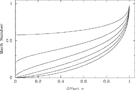
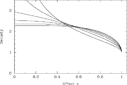
The Mach number and density distributions are given in Figs 1 and 2 respectively, as a function of the fractional offset , for six different values of (including , which is uniform mass loading). The densities are normalized such that the edge density is unity for each (i.e. so at ).
The emission measure, , is given in Fig. 3 as a function of the fractional offset, , from the central star, for each . The individual plots are calculated using the density distributions of Fig. 2. The and distributions are centre-brightened and reproduce a core–halo morphology. A photoevaporating disc, as described by Hollenbach et al. [Hollenbach et al. 1994], could provide additional mass injection close to the central star. However, on its own, a photoevaporating disc gives an approximately fall-off away from the disc, so additional mass injecting sources would be needed away from the centre. The other plots show progressively a more uniform brightness with increasing . These other models could reproduce satisfactorily UCHiiR that have spherical uniform morphologies.
The corresponding optically thin recombination line profiles are shown in Fig. 4. We assume that the gas emits with a Gaussian profile, and we neglect effects such as pressure broadening [Roelfsema & Goss 1992] which will add characteristic Lorentzian wings to the profiles. They are viewed through lines of sight with offsets of from the central star and are individually normalized to their peak intensity. The is distinct but is only slightly broader than the higher plots which are practically identical and appear almost superimposed in the figure. This shows that, in this case, line profiles will not be able to differentiate between the models described above. These Gaussian-like profiles are produced simply because the gas everywhere has a subsonic velocity.


2.2 Mach number dependent mass injection
We now take the mass injection rate to be proportional to which is appropriate for mass loading by hydrodynamical ablation. Substituting into equations (5) and (6) gives
| (12) |
| (13) |
There is no non-trivial solution for hydrodynamic ablation that passes through , so we assume that the flow is started off by another mechanism such as photoionization, or by a stellar wind shocking, and match this at some radius to our model here. As one of our boundary conditions we have at . Varying the other boundary condition (e.g. at ) generates a family of solutions for the velocity and density for each . We present these solutions in Figs 5 and 6 for the case of only, for clarity.
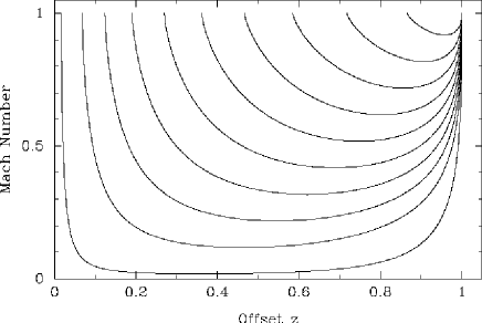
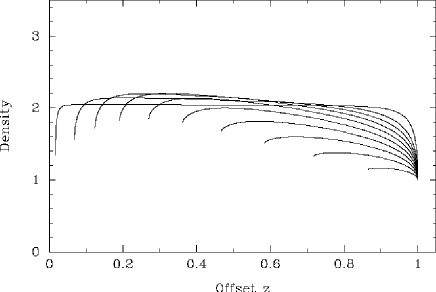
To show the variation of these solutions with , we select the solution that passes through the point at with as an example. We retain the other boundary condition at and examine the same six power laws as before. The full velocity and density solutions for this particular pair of boundary conditions are shown in Figs 7 and 8. The densities are normalized to the same edge density as before. The variation of the flows between different values of is less marked than in the Mach number independent models of the previous subsection. The Mach number dependence of the mass injection rate means that mass loading is enhanced in a shell towards the edge of the region. This effect is most pronounced for the positive values of . Gravitational effects in fact may become important at the parts of the flow with particularly low velocities or at small radii, and we will discuss this elsewhere.


In Fig. 9 we show the emission measure as a function of fractional offset . Since there may be several ways in which the flow is initiated, we neglect any emission from this inner zone which is not part of the solution. This gives the dip for offsets less than , since our line of sight contains a sphere with no emission. It can be seen that the emission measures are quite similar for the different radial fall-offs. Comparing these with the emission measures for the flow loaded by photoionization ablation (shown in Fig. 3), we see that the Mach number dependent models are similar to the photoionization loaded flows with , and thus they could also describe a UCHiiR with uniform morphology. An optically thin line profile is shown in Fig. 10 for a fractional offset . The profile is hard to distinguish from the profiles of the photoionization loaded flows with seen in Fig. 4. Only one profile is shown because the six models give practically the same line profiles.


3 UCHiiR in terms of a supersonic–subsonic flow with an internal shock
In this section, we combine the results of the previous sections with those of Paper I to allow for the possibility that the flow is decelerated by mass loading to such an extent that a wind termination shock occurs before the recombination front is reached. This will occur if the Mach number in the supersonic flow is predicted by the ballistic approximation to reach values of before the recombination front [Williams, Hartquist & Dyson 1995]. In Paper I we used the conservation of mass and momentum to find velocity and density distributions for a fully supersonic, uniformly mass loaded flow:
| (14) |
The mass loading mechanism in the supersonic flow before the shock radius is independent of Mach number [Hartquist et al. 1986]. The emission will be dominated by the low-velocity, high-density gas at the edge of the mass loading region. The high velocity of the unshocked wind will mean that it stands well clear of the near-Gaussian profiles predicted for the subsonic region. However in all but the cases with the lowest pre-shock velocities, or thinnest subsonic shells, the high density in the subsonic region (which is a factor substantially more than 4 higher than the pre-shock density because of the cooling of the shocked gas) will mean that this low-velocity gas dominates the emission. For simplicity, we assume that the mass injection rate is independent of flow velocity and radial distance so that .
In the emission measure plot shown in Fig. 11 a shell morphology is clearly apparent. The emission at offsets less than the shock radius is from the subsonic gas in our line of sight and not from the supersonic gas which contributes very little to the emission. In fact, even if there were noticeable emission from the supersonic gas, the overall emission measure would still be essentially that of a shell because the density distribution (equation 14) is strongly weighted to the edge of the supersonic region. In Fig. 12 we show an optically thin line profile for this shock radius taken at a line of sight with offset , close to the centre. The profile consists of two near-Gaussian components, generated by the parts of the shell that are moving towards and away from us, separated in velocity by an amount that is a fraction of their widths. This results in a line profile that is broader than those produced using the fully subsonic models described earlier. We find very similar results if the mass loading is Mach number dependent.


4 conclusions
In this paper we have modelled UCHiiR as subsonic flows from photoionized clumpy clouds lying in the vicinity of an ionizing stellar source. We have found that, by assuming a simple spatial distribution of clumps and allowing the flow to be supersonic, subsonic or both (with a separating shock), we can reproduce three different UCHiiR morphologies.
For the fully subsonic models, we have found that a radial dependence of the mass injection rate is more important for the photoionization-induced subsonic flow. The emission measures show that the flows are less centre-brightened than the photoionization flow. Either of the two types of model can naturally describe the uniform spherical UCHiiR. In addition, the photoionization flow with or can satisfactorily explain the core–halo UCHiiR. Line profiles are of no use in distinguishing between the two different flows. For both cases we have calculated velocity and density distributions that will be used in more detailed future work.
Paper I showed that a supersonic wind-blown model could reproduce the shell morphology but with broad, double-peaked line profiles. In contrast, we have suggested in Section 3 that if a shock forms before the recombination front then a shell morphology is retained but with a single peaked line profile. Which type an individual object is will be settled by high-resolution observations of the velocity structure of the region.
At high enough resolution, the largest individual clumps will begin to be resolved. The irregular/multiple-peaked UCHiiR are perhaps simply a collection of large clumps which are ionized on their outsides by the central source. The ‘hypercompact’ continuum sources found in clusters by Gaume et al. [Gaume et al. 1995] are perhaps clumps such as this. Preliminary work suggests that a non-spherically symmetric distribution in the mass loading around the region can describe the arc-like UCHiiR (Paper III).
The solutions to the subsonic flow equations may be applicable to other objects. Although visible H ii regions are older and more evolved than UCHiiR, their morphologies have been found to be very similar to those of UCHiiR [Fich 1993], and this may imply that they could be used to test some of the observational diagnostics described here and in Paper I. The extent of the neutral H i envelopes around H ii regions is explained by the structure of photodissociation regions in clumpy clouds [Howe et al. 1991]. However, Roger & Dewdney [Roger & Dewdney 1992] note that the outflowing H i shocks seen around H ii regions (e.g. Kuchar & Bania 1993) are not as thin and do not have as high densities as predicted by standard theory. Such low-density shells of H i may result from support by the swept-up magnetic fields [Mathews & O’Dell 1969]. We would suggest that the neutral winds beyond recombination fronts would also explain these structures. If this is the case, then observations of H ii regions agreeing with our predictions for UCHiiR would lend support to our models.
We will address elsewhere the dynamical effects that dust will have on these models, consider the intermediate-scale structure in the regions and incorporate any gravitational effects.
Acknowledgments
This work was supported by PPARC both through the Rolling Grant to the Astronomy Group at Manchester (RJRW) and through a Graduate Studentship (MPR).
References
- [Churchwell 1990] Churchwell E., 1990, A&AR, 2, 79
- [De Pree et al. 1995] De Pree C. G., Gaume R. A., Goss W. M., Claussen M. J., 1995, ApJ, 451, 284
- [Dyson 1994] Dyson J. E., 1994, in Ray T. P., ed., Proceedings of the Berlin EADN Summer School. Springer-Verlag, Berlin, p. 93
- [Dyson, Williams & Redman 1995] Dyson J. E., Williams R. J. R., Redman M. P., 1995, MNRAS, 277, 700 (Paper I)
- [Fich 1993] Fich M., 1993, ApJS, 86, 475
- [Gaume, Fey & Claussen 1994] Gaume R. A., Fey A. L., Claussen M. J., 1994, ApJ, 432, 648
- [Gaume et al. 1995] Gaume R. A., Claussen M. J., De Pree C. G., Goss W. M., Mehringer D. M., 1995, ApJ, 449, 663
- [Hartquist et al. 1986] Hartquist T. W., Dyson J. E., Pettini M., Smith. L. J., 1986, MNRAS, 211, 715
- [Hollenbach et al. 1994] Hollenbach D., Johnstone D., Lizano S., Shu. F., 1994, ApJ, 428, 654
- [Howe et al. 1991] Howe J. E., Jaffe D. T., Genzel R., Stacey G. J., 1991, ApJ, 373, 158
- [Kuchar & Bania 1993] Kuchar T. A., Bania T. M., 1993, ApJ, 414, 664
- [Kurtz, Churchwell & Wood1994] Kurtz S., Churchwell E., Wood D. O. S., 1994, ApJS, 91, 659 (KCW)
- [Mac Low et al. 1991] Mac Low M. M., Van Buren D., Wood D. O. S., Churchwell E., 1991, ApJ, 369, 395
- [Mathews & O’Dell 1969] Mathews W. G., O’Dell C. R., 1969, ARA&A, 7, 67
- [Roelfsema & Goss 1992] Roelfsema P. R., Goss W. M., 1992, A&AR, 4, 161
- [Roger & Dewdney 1992] Roger R. S., Dewdney P. E., 1992, ApJ, 385, 536
- [Van Buren & Mac Low 1992] Van Buren D., Mac Low M. M., 1992, ApJ, 394, 534
- [Van Buren et al. 1990] Van Buren D., Mac Low M. M., Wood D., Churchwell E., 1990, ApJ, 353, 570
- [Williams & Dyson 1994] Williams R. J. R., Dyson J. E., 1994, MNRAS, 270, L52
- [Williams, Dyson & Redman 1996] Williams R. J. R., Dyson J. E., Redman M. P., 1996, MNRAS, in press (Paper III)
- [Williams, Hartquist & Dyson 1995] Williams R. J. R., Hartquist T. W., Dyson J. E., 1995, ApJ, 446, 759
- [Wood & Churchwell 1989] Wood D. O. S., Churchwell E., 1989, ApJS, 69, 831