Clover - A B-mode polarization experiment
Abstract
Clover is a new instrument being built to detect the B-mode polarization of the CMB. It consists of three telescopes operating at 97, 150, and 220 GHz and will be sited in Chile at the Llano de Chajnantor. Each telescope assembly is scaled to give a constant beam size of 8 arcmin and feeds an array of between 320 and 512 finline-coupled TES bolometers. Here we describe the design, current status and scientific prospects of the instrument.
keywords:
cosmology , experiment , cosmic microwave background , polarization1 Introduction
The polarization of the cosmic microwave background (CMB) contains unique information about the early universe. In particular, the presence of a tensor (gravitational wave) component, which can only be determined with limited accuracy from the temperature anisotropies, produces a unique signature in the CMB polarization, the B-mode signal. The polarization field can be decomposed into curl-free (E-mode) and curl (B-mode) components, and the polarization from scalar fluctuations produces no B-mode in linear theory. Provided spurious sources of B-mode signal (such as foregrounds and systematic effects) can be controlled, detection of a B-mode signal would thus constitute a direct measurement of primordial gravitational waves and would measure fundamental parameters of inflation theory. However, the expected amplitude of the signal is exceedingly small (K) and very precise control of systematic effects, as well as raw sensitivity, will be needed to measure it reliably.
Clover is a project to attempt to measure the B-mode polarization of the CMB. It is a collaboration between the Universities of Oxford, Cardiff, Cambridge and Manchester, with the detector read-out technology supplied by the University of British Columbia and the National Institute of Standards and Technology. Clover consists of three separate, scaled instruments operating at 97, 150 and 220 GHz to provide discrimination between the CMB and foregrounds. The telescopes use the Compact Range Antenna design, which has particularly low aberrations across a large focal plane. The telescope focal planes will be populated with arrays of polarimeters, in which the polarizations in each pixel are rotated, separated and detected so as to extract the Stokes parameters Q and U, modulated by the polarization rotation. Intensity can also be recovered, but only modulated by the telescope scanning across the sky. The signals will be detected using arrays of superconducting transition edge sensors (TESs), which allow background-limited sensitivity and can be fabricated in sufficient quantity using lithographic techniques.
It is planned to site Clover at Chajnantor in Chile, where the atmospheric transparency is excellent, and the latitude allows for constant-elevation scans of a single sky area to be cross-linked. The beamwidth at each frequency will be 8 arcmin and the telescopes will be scanned to give sensitivity over an angular multipole range of . This will allow measurement of the B-mode signal over the range of scales expected for the signal from primordial gravitational waves. The sensitivity should be around 220 per pixel at 150 GHz, sufficient for the sensitivity to be limited by the B-mode lensing foreground after two seasons of observation. This will result in a sensitivity to gravitational waves equivalent to a tensor-to-scalar ratio, , of .
2 Instrument design
The principles behind the Clover design are to have the cleanest possible optical system, a large number of highly sensitive focal plane detectors, and multiple levels of modulation of the signal to differentiate between astronomical and systematic signals.
2.1 Telescope Optics
Clover uses the Compact Range Antenna design (also known as a crossed Dragone) which is an off-axis un-blocked aperture design using a concave hyperboloidal secondary and a paraboloidal primary. Despite being off-axis this system has a very large focal plane with low aberrations and cross-polarization Yassin-CRA , much more so than the equivalent aperture Gregorian, for example. The drawback is that the secondary has to be roughly the same size as the primary, but this is not a serious issue for a modestly-sized ground-based telescope.
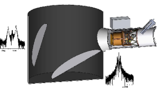
The Clover 97-GHz system uses a primary with a 1.8-m projected aperture. This is significantly under-illuminated to minimise sidelobes and spillover, giving a beam of about 8 arcmin. The far sidelobe levels of the basic optical system are extremely low over the whole sphere (typically -80 dB), apart from spillover around the two mirrors (which is less than 1 percent of the total power). This spillover signal is absorbed by a cylindrical absorbing screen surrounding the optics (see Fig. 1). This screen adds 5–10 percent to the power load on the detectors, but prevents polarized sidelobes from reaching the ground or bright astronomical sources.
Each optical assembly (one for each frequency) is mounted on a three-axis mount (azimuth, elevation and boresight rotation) which will be covered with a retractable dome to provide protection when not observing. The mount provides full sky coverage down to the horizon, azimuth slew speeds up to 20 deg/s, and over 180 degrees of boresight rotation (although in practice the useful degree of boresight rotation is limited by the need to keep the pulse-tube cooler of the cryostat within deg of vertical).
2.2 Cryogenics
The Clover detectors need to be cooled to less than 100 mK in order to provide optimum performance. This is achieved using three cooling mechanisms: a Cryomech PT-410 pulse-tube cooler which provides 40-K and 4-K stages, a high-capacity Simon Chase He-10 cooler providing 2-K, 370-mK and 250-mK stages, and a custom-made miniature dilution refrigerator Tele06 , providing final cooling of the detectors to 60 mK. The pulse tube cooler has the motor and expansion stages separated by flexible stainless steel lines to minimise vibrations in the cryostat (although TES detectors are much less sensitive to microphonics than, for example, NTD bolometers). The temperature of the cold stages will be controlled using a closed-loop system with a long-term design stability of 3.5 K rms. A stack of metal-mesh filters provides bandpass filtering and infra-red blocking: the size of the cryostat window is limited by the largest such filters that can be manufactured, to 300 mm. This fixes the largest number of feedhorns that can be used; at 97 GHz this is 160, but at the higher frequencies, more than the planned number of 256 horns could be accommodated.
2.3 Feedhorn Arrays
The feedhorns are corrugated, profiled horns, which have a steeper beam fall-off than conical corrugated horns, and hence give less spillover, particularly for the edge feeds in the array. Each horn is approximately 18 mm diameter and 100 mm long (at 97 GHz; scaled at the other frequencies). The horns will be individually electroformed and bolted to the polarimeter block.
2.4 Polarimeter
The polarimeter has to provide for separation of the orthogonal polarizations and their modulation. We will describe here the 97-GHz system, which is the most advanced in design. Following the feedhorn, the signal passes through a mechanical waveguide polarization rotator, consisting of a ‘half wave plate’ section, implemented with iris polarizers in circular waveguide, which has extremely low insertion loss and return loss, and very flat phase response across the whole (30 percent) band. Following the polarization rotator, the polarizations are separated in a waveguide orthomode transducer, which outputs two rectangular waveguides. These interface to the detector block, in which each polarization is detected with a separate finline-coupled TES chip.
At the higher frequencies it is more difficult to implement the mechanical rotating waveguides, and we are considering several options, including a single rotating waveplate in front of the horn array as well as planar circuit phase switches phase-switch . In this latter design, a switch is implemented using a superconducting nanostrip shorting a transmission line; the device can be made to switch between reflection and transmission by biassing the nanostrip with a current exceeding the superconducting critical current density. Given such a switch, there are several ways of implementing a transmission-line phase switch which can insert a 90- or 180-degree phase shift. The polarimeter would then consist of a phase switch in each of the OMT outputs, followed by a hybrid coupler and then the detectors. Although more complicated in principle, such a polarimeter could be implemented entirely on a single lithographed chip.
2.5 Detectors
Clover uses finline-coupled superconducting transition-edge sensor (TES) bolometers as detectors. To detect the two polarizations the 97-GHz telescope has 320 detectors while the 150 and 220-GHz telescopes have 512 detectors each. The detectors are cooled to 100 mK in order to achieve the target NEPs (1.5, 2.5, and ). Each detector is fabricated as a single chip to ensure a 100% operational focal plane. The detectors are contained in linear modules made of copper which form split-block waveguides and are read out with time-division SQUID multiplexers Cher99 ; deKorte03 fabricated at the National Institute of Standards and Technology. Further amplification of the multiplexed signals is provided by SQUID series arraysWelt93 .
Power is coupled from the waveguide to the TES planar circuit using an antipodal finline taper consisting of two superconducting fins of Nb separated by 400 nm of SiO2 Yass95 ; Yass2000 (see Fig. 2). Before the fins overlap, the thickness of the SiO2 is much less than that of the silicon substrate and the structure behaves as a unilateral finline. As the fins overlap, the structure starts to behave like a parallel-plate waveguide with an effective width equal to the overlap region. When the width of the overlap region becomes large enough for fringing effects to be negligible, a transition to a microstrip mode is performed. The microstrip is then tapered to the required width.
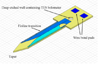
Clover’s bolometers are low-stress silicon nitride islands suspended on four legs (see Fig. 2). The nitride is 0.5 thick. The thermal conductance to the thermal bath is controlled by the four nitride legs. The microstrip carrying power from the finline to the bolometer is terminated by a 20- Au/Cu resistor which dissipates the incoming power as heat that the TES can detect. The TES films in Clover are Mo/Cu proximity-effect bilayers, with transitions as sharp as 1–2 mK for high sensitivity. The operating temperature of Clover’s detectors is chosen to meet the NEP requirements, which are dominated by phonon noise.
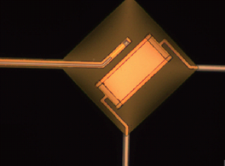
We have produced prototype detectors for Clover and found that the TES films are of high quality, making for sensitive detectors, although more development of the thermal design is needed to achieve the required power handling. The measured electrical NEP is close to the phonon noise level. Figure 3 shows a prototype Clover detector chip.
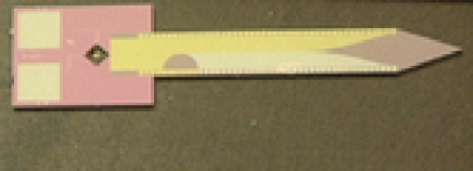
The feedhorns are arranged in a hexagonal array. However, the multiplexer chips we are using lend themselves more naturally to a planar configuration where we have up to 16 horns in a row. As shown in Fig. 4, we split the 97-GHz focal plane into three regions. The two waveguides corresponding to each horn are arranged so that they are all parallel within one of these regions. This allows us to cover each region with linear detector blocks stacked on top of each other with an offset to match the hexagonal horn pitch. The orientation of one of these detector blocks is shown by a dark rectangle in each of the three regions. The 97-GHz focal plane needs 22 detector blocks to cover it. The scheme for covering the 150- and 220-GHz focal planes is similar, except that the horns are arranged in a hexagon with a side of ten horns.
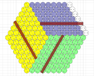
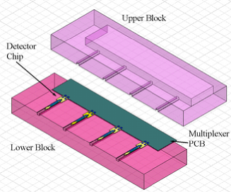
A simplified view of a detector block holding four detectors is shown in Fig. 4. The detector modules contain 16 or 20 detectors each for compatibility with the hexagonal arrays of horns in the telescopes’ focal planes. The detector block comes in two halves, upper and lower. When these are put together they form split-block waveguides, into which the finlines protrude.
3 Site and Observing Strategy
Clover is planned to be sited at the Llano de Chajnantor in northern Chile, at latitude deg. This site combines relative ease of access (it can be reached by public roads) with superb millimetre and sub-millimetre observing conditions, and is the site of many planned or existing instruments (e.g. CBI, QUIET, ALMA, APEX, ACT).
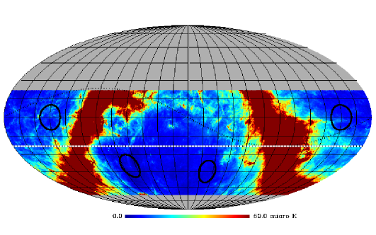
Clover will likely observe observe four patches of sky, each of radius , distributed as equally as possible in right ascension in order to provide year-round useful observing. The exact fields will be chosen to be in areas identified to have low total-intensity emission and predicted to have low levels of diffuse, polarized galactic foregrounds (synchrotron and thermal dust emission). While not much is known about low-level polarized foregrounds, models do exist (e.g. giardino , SFD ), which we extrapolate to obtain estimates in our observing bands. The sky patches must also be observable at high elevation for long periods, but not go overhead, since constant-elevation scanning is not possible at the zenith. From Chajnantor there are two general areas that fulfil this requirement, one in each Galactic hemisphere, at RA = 21h – 05h, Dec and RA = 08h – 14h DEC . Fig. 5 shows the predicted total intensity of synchrotron and dust emission at 97 GHz and the positions of four suitable fields visible from Chajnantor.
Our adopted scanning strategy is based on scanning at constant elevation, which eliminates large baselines on each scan due to changing airmass. It is important that each field can be observed with scans at a wide range of position angles. This is necessary for the mapping strategy, which uses the redundancy introduced by the cross-coverage to fit out and remove low-order components along each scan due to residual atmospheric fluctuations or receiver instabilities. A range of crossing angles will also be important for averaging down any polarization systematics.
4 Power spectrum and parameter forecasts
The errors on the power spectra and the tensor-to-scalar ratio have been forecasted using a purpose-written Fisher-matrix code. This properly accounts for the effect of the survey geometry on the power spectra errors and their covariance. In particular, it includes information loss in the errors due to - mixing due to the finite sky coverage and the small effect of (anti-)correlations between neighbouring bandpower estimates. We assume that there are no significant pixel-pixel correlations, which should be the case for Clover maps after de-striping, and we have not attempted to account properly for the change in noise properties in the maps due to foreground removal, nor do we take account of any foreground residuals. Since the polarized foregrounds at Clover frequencies are still highly uncertain, our noise figures are based solely on the middle, 150-GHz channel which crudely (but consistently) accounts for removal of synchrotron emission with the lowest frequency and thermal dust emission with the highest. We include the -mode lensing signal as a Gaussian noise term which is approximately correct on the large scales where the gravitational-wave signal resides and where the Clover thermal noise level is comparable to the lensing signal. We have not attempted to clean out the lens-induced -modes although this should be possible to some extent with Clover data and would reduce the errors a little on .
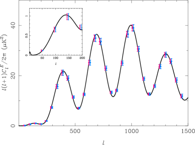
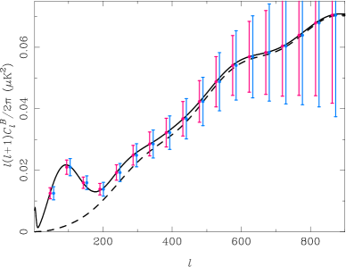
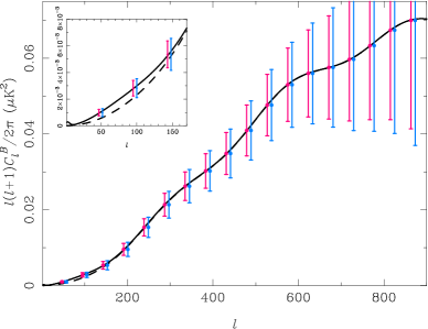
Our forecasts for the power spectrum errors after two years of operation are presented in Fig. 6. The total survey area is . This is close to optimal in terms of balancing thermal variance against the sample variance of the lens-induced modes. We have assumed year-round, night-time observing with an average observing efficiency (taking into account bad weather, down time and calibration) of about 40 percent. In each case we show the one-sigma errors on bandpowers , after marginalising over neighbouring bands. We adopt two values for the tensor-to-scalar ratio: , the current 95% limit from WMAP3 temperature and -mode polarization data, and which is the design target for Clover.
Propagating the band-power errors in , after marginalising over , to errors in the tensor-to-scalar ratio gives a one-sigma error on in the null hypothesis of 0.004. Marginalising over -modes produces only a very small degradation compared to when we include them in the analysis showing that the constraint on is indeed driven by the -modes. We only allow to vary which neglects the small uncertainty in the lens-induced -mode power.
We end by noting that the angular resolution of Clover (8 arcmin) also benefits the secondary science that we can do with Clover. Examples include lensing reconstruction from the polarization maps and hence constraints on dark-sector parameters (e.g. neutrino masses and dark energy properties), and searches for the imprint of cosmic (super)strings or primordial magnetic fields in the -mode power spectrum on intermediate scales. In addition, the improved angular resolution of the Clover survey will improve the Galactic science (e.g. magnetic field morphology and dust grain properties) returned from Clover.
Acknowledgements
Clover is funded by the Particle Physics and Astronomy Research Council. ACT is supported by a PPARC fellowship. The work described here is the result of many peoples’ effort within the Clover collaboration. Particular thanks to Damian Audley and Anthony Challinor for help with these proceedings.
References
- (1) G. Yassin, P. K. Grimes, S. B. Sorenson, Proc. of the 16th Int. Symp. on Space Terahertz Technology, 2005, Gothenburg, Sweden, in press.
- (2) P. K.Grimes, G. Yassin, L. S. Kuzmin, P. D. Mauskopf, E. Otto, M. E. Jones, C. E. North, Proc. SPIE, Vol. 6275, 76, 2006.
- (3) G. Yassin and S. Withington, J. Phys. D, 28, 1983 (1995).
- (4) G. Yassin, S. Withington, M. Buffey, K. Jacobs, and S. Wulff, IEEE Trans. on Microwave Theory and Techniques, 48, 662 (2000).
- (5) G. Teleberg and L. Piccirillo, 2006, Proc. SPIE, 6275, in press.
- (6) J. A. Chervenak, K. D. Irwin, E. N. Grossman, J. M. Martinis, C. D. Reintsema, and M. E. Huber, Appl. Phys. Lett., 74, 4043 (1999).
- (7) P. A. J. de Korte, J. Beyer, S. Deiker, G. C. Hilton, K. D. Irwin, M. Macintosh, S. W. Nam, C. D. Reintsema, L. R. Vale, and M. E. Huber, Rev. Sci. Inst., 74, 3807 (2003).
- (8) R. P. Welty and J. M. Martinis, IEEE Trans. Appl. Supercond., 3, 2605 (1993).
- (9) G. Giardino, A. J. Banday, K. M. Gorski, K. Bennett, J. L. Jonas, J. Tauber, 2002, A&A 387, 82
- (10) Schlegel, Finkbiner & Davis, 1998, ApJ, 500, 525