Global Asymmetry of the Heliosphere
Abstract
Opher et al. opher06 showed that an interstellar magnetic field parallel to the plane defined by the deflection of interstellar hydrogen atoms can produce a north/south asymmetry in the distortion of the solar wind termination shock. This distortion is consistent with Voyager 1 and Voyager 2 observations of the direction of field-aligned streaming of the termination shock particles upstream the shock. The model also indicates that such a distortion will result in a significant north/south asymmetry in the distance to the shock and the thickness of heliosheath. The two Voyager spacecraft should reveal the nature and degree of the asymmetry in the termination shock and heliosheath.
:
96.50.Xy,96.60.-j,96.60.Iv1 Introduction
After 27 years of anticipation, Voyager 1 crossed the inward moving termination shock (TS) at and is now exploring the heliosheath burlaga ; decker ; stone05 . The twin Voyager spacecraft are probing the northern and southern hemispheres of the heliosphere. As Voyager 1 crossed the TS and began exploring the heliosheath it has become increasingly clear that this previously unexplored region is full of surprises. Using in situ spacecraft data to constrain the shape of the heliosphere is challenging because they are single point observations. For a quantitative global understanding of the three dimensional structure of the heliosphere, it is necessary to use modeling in conjunction with observations to probe this region.
In mid 2002, Voyager 1 began observing strong beams of energetic termination shock particles (TSPs) streaming outward along the spiral magnetic field. The strong upstream TSP beams were observed much of the time until Voyager 1 crossed the shock at in December 2004. Jokipii et al. jokipii and Stone et al. stone05 suggested that the upstream beaming resulted from a non-spherical shock. For a spherical shock, Voyager 1 would observe upstream TSPs streaming inward along the magnetic field. With a non-spherical shock, Voyager 1 could be connected to the TS along magnetic field lines that crossed the TS (the source of TSPs) and then crossed back into the supersonic solar wind.
In order to know Voyager 1 measurements in 2002 it is important to understand the shape of the heliosphere. The interaction of the solar system with the local interstellar medium requires an intensive modeling effort because this problem is inherently three dimensional and involves solar and interstellar magnetic fields, ionized and neutral atoms, and cosmic rays(suess, ; zank, ). The size and shape of the heliosphere will depend on the properties of both the solar wind and the local interstellar medium.
Based on the polarization of light from nearby stars, Frisch frisch ; frisch1 suggested that the magnetic field direction is parallel to the galactic plane (and directed toward ). Voyager 3kHz radio emission data also show preferred source locations in a plane parallel to the galactic plane kur . On the other hand, Lallement et al. lall , mapping the solar Lyman- radiation that is resonantly backscattered by interstellar hydrogen atoms, found that the neutral hydrogen flow direction differs from the helium flow direction by . The plane of the H deflection (HDP) is tilted from the ecliptic plane by and is consistent with an interstellar magnetic field parallel to the HDP planeizmo . However, Pogorolev et al.pog06 show that the H deflection does not uniquely determine the plane of the magnetic field.
If the interstellar magnetic field is inclined to the interstellar velocity, it can produce a lateral or north-south asymmetry in the heliospheric shape pog ; ratk . Opher et al. opher06 showed that that an interstellar magnetic field parallel to the H-deflection plane (HDP) can produce a north/south asymmetry in solar wind termination shock that is consistent with Voyager 1 and Voyager 2 observations of the direction of streaming of the particles. We review these results and comment on the Heliosphere global asymmetry.
2 Results
The model that we used is based on the BATS-R-US code, a three-dimensional magnetohydrodynamic (MHD) parallel, adaptive grid code developed by University of Michigangombosi and adapted for the outer heliosphereopher03 ; opher04 . The boundary conditions are described in opher06 . We considered fields parallel to the HDP with different inclination angles , where is the angle between the interstellar magnetic field and the interstellar wind velocity (Figure 1).
The coordinate system in Figure 1 is the conventional one for MHD heliospheric models, with the -axis as the solar rotation axis of the sun, the interstellar velocity direction in the direction, with completing the right handed coordinate system. This coordinate system is essentially the heliographic inertial coordinate system (HGI), except that in the heliographic inertial coordinates, the direction of the interstellar wind is (HGI latitude) and (HGI longitude). The HGI latitude for Voyager 1 and Voyager 2 become and relative to the interstellar wind in the plane, a latitude difference of . Although this conventional coordinate system ignores the tilt of the solar rotation axis in respect to the interstellar wind, more significantly it ignores the tilt of the heliospheric current sheet.
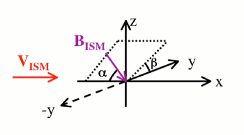
Figure 2 shows the heliopause (HP) surface for in the HDP plane with an inclination angle , , and (the same values are used in Figures 2-4). The heliopause
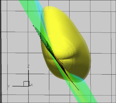
is asymmetric, north/south and east/west. It is distorted in the direction of the plane of the interstellar magnetic field and bulges outward in the northern hemisphere where the heliospheric current sheet is deflected (see also Figure 3). The current sheet deflection also results in an indentation at the solar equatorial plane that is apparent in both Figures 2 and 3. The heliosheath is thicker in the north where the HCS is deflected. There is a smaller north/south asymmetry in the termination shock that will be discussed further below.
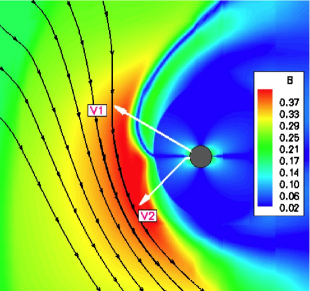
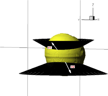
Figure 4 shows the intersection of the cones at and that contain the spiral solar magnetic field lines crossing Voyager 1 and Voyager 2 respectively. In both the northern and southern hemisphere, the cones intersect the surface of the termination shock nearer the equator in the nose region where the shock is closer to the Sun. The termination shock also bulges out in the northern hemisphere. As discussed in Opher et al.opher06 , upstream of the shock Voyager 1 is connected to the shock along the field line in the direction toward the Sun, allowing TSPs to stream outward along the field as observed.
The distortion is larger in the southern hemisphere, so that upwind of the shock Voyager 2 is connected to the shock and the TSP streaming should be inward along the spiral magnetic field line, opposite to that for Voyager 1, as has been observed cummings .
The radial distance to the shock at the latitudes of Voyager 1 and 2 decreases significantly as the inclination angle increases from to , with the shock to closer in the south at Voyager 2 than in the north at Voyager 1opher06 .
Although there was no direct indication of how far Voyager 1 was from the shock when the upstream episodes of TSPs were observed, MHD models based on Voyager 2 solar wind pressure measurements rich indicate that the distance was less than to . This suggests that is likely in the range of to for which the distortion is maximumopher06 .
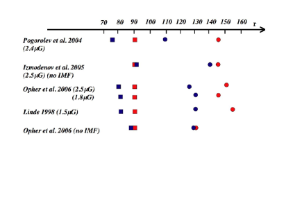
Figure 5 summarizes the locations of the TS and the HP scaled from various recent models. We normalized the model results to (red squares), the estimated average location of the shock at the latitude of Voyager 1 as the shock moves inward and outward over the solar cycle. The conclusions that can be drawn are: a) For the models including an interplanetary magnetic field, the TS ranged between to for Voyager 2; b) There is somewhat less North-South asymmetry with a weaker ; c) The heliosheath thickness at Voyager 1 is about to . For the model that has an interplanetary magnetic field and strong , the thickness at Voyager 2 is to . Although this is a preliminary calculation and does not incorporate a tilted current sheet, it does indicate the possibility of a significant north-south asymmetry in the heliosheath thickness; d) These models do not include neutrals that may affect the degree of asymmetry. However, models such as Linde 1998 linde98 (same model as in Linde et al. 1998 linde ) that include neutrals as a fluid show a north-south asymmetry with a ratio of for the north/south distance to the termination shock and for the ratio for the HP distance, similar to models without neutrals. Izmodenov et al. izmo , using a kinetic treatment with the in the HDP plane, found a smaller north-south asymmetry. Their treatment, however, did not include the solar magnetic field.
3 Conclusions
The recent results by Opher et al.opher06 indicate that an interstellar magnetic field in the H-deflection plane can distort the heliosphere in a manner consistent with the streaming observed by Voyager 1 and Voyager 2. The model also indicates that such a distortion will result in a significant north/south asymmetry in the distance to the shock and the thickness of heliosheath, and it is reasonable to expect that Voyager 2 will encounter the shock in the next two years. When combined with a more realistic heliospheric model with a tilted current sheet, this should provide additional information about the strength and inclination of the local interstellar magnetic field.
References
- (1) Opher, M., Stone, E. C., Liewer, P.C., Astrophys. J. 640, L71-L74 (2006).
- (2) Burlaga, L. F., Ness, N. F., Acuna, M. H., Lepping, R. P., Connerney, J. E. P., Stone, E. C., & McDonald, F. B., Science 23, 2027 (2005).
- (3) Decker, R., Krimigis, S. M., Roelof, E. C., Hill, M. E., Armstrong, T. P., Gloeckler, G., Hamilton, D. C., & Lanzerotti, L. J., Science 23, 2020 (2005).
- (4) Stone, E. C., Cummings, A. C., McDonald, F. B., Heikkila, B. C., Lal, N., & Webber, W. R., Science 23, 2017 (2005).
- (5) Jokipii, J. R., Giacalone, J., Kota, Astrophys. J. 611, L141 (2004).
- (6) Suess, S., J. Geophys. Res. 93, 15147 (1993).
- (7) Zank, G. P. et al., Space Sci. Rev. 89, 413 (1999).
- (8) Frisch, P. C., Physics of the Outer Heliosphere, 19 (1990).
- (9) Frisch, P. C., Astrophys. J. 632, L143 (2005).
- (10) Kurth, W. S., Gurnett, D. A., J. Geophys. Res. 108, LIS 2-1 (2003).
- (11) Lallement, R., Quemerais, E., J. L. Bertaux, S. Ferron, D. Koutroumpa, R. Pellinen, Science 307, 1449 (2005).
- (12) Izmodenov, V., Alexashov, D., & Myasnikov, A., Astron. Astrophys. 437, L35 (2005).
- (13) Pogorolev, N., Zank, G. P., Astrophs. J. 636, Issue 2, L161-L164 (2006).
- (14) Pogorolev, N., Zank, G. P., & Ogino, T., Astrophys. J. 614, 1007 (2004).
- (15) Ratkiewicz, R. and Ben-Jaffel, L., J. Geophys. Res. 107, Issue A1, pp. SSH 2-1 (2002).
- (16) Gombosi, T., Powell, K. G. & de Zeeuw, D. L., J. Geophys. Res. 99, 21525 (1999).
- (17) Opher, M., Liewer, P. C., Gombosi, T. I., Manchester, W., DeZeeuw, D. L., Sokolov, I., Toth, G., Astrophys. J. 591, L61 (2003).
- (18) Opher, M., Liewer, P. C., Velli, M., Bettarini, L., Gombosi, T. I., Manchester, W., DeZeeuw, D. L., Toth, G., Sokolov, I., Astrophys. J. 611, 575 (2004).
- (19) Cummings, A. C., Stone, E. C., McDonald, F. B., Heikkila, B. C., Lal, N., Webber, W. R., AGUFMSH51A-1184 (2005).
- (20) Richardson, J. D., Wang, C., AGUFMSH51A-1186 (2005).
- (21) Linde, T. J., A Three-Dimensional Adaptive Multifluid MHD Model of the Heliosphere, PhD thesis, Univ. of Michigan (1998).
- (22) Linde, T. J., Gombosi, T. I., Roe, P. L., Powell, K. G., DeZeeuw, D. L., J. Geophys. Res. 103, 1889 (1998).