Galactic warps induced by cosmic infall
Abstract
Recent ideas for the origin and persistence of the warps commonly observed in disc galaxies have focused on cosmic infall. We present -body simulations of an idealized form of cosmic infall onto a disc galaxy and obtain a warp that closely resembles those observed. The inner disc tilts remarkably rigidly, indicating strong cohesion due to self-gravity. The line of nodes of the warp inside is straight, while that beyond generally forms a loosely-wound, leading spiral in agreement with Briggs’s rules. We focus on the mechanism of the warp and show that the leading spiral arises from the torques from the misaligned inner disc and its associated inner oblate halo. The fact that the line of nodes of most warps forms a leading spiral might imply that the disc mass is significant in the centre. If the line of nodes can be traced to very large radii in future observations, it may reveal information on the mass distribution of the outer halo. The warp is not strongly damped by the halo because the precession rate of the inner disc is slow and the inner halo generally remains aligned with the inner disc. Thus even after the imposed quadrupolar perturbation is removed, the warp persists for a few Gyrs, by which time another infall event can be expected.
keywords:
stellar dynamics — galaxies: evolution — galaxies: kinematics and dynamics — galaxies: structure1 Introduction
The optically visible parts of galactic discs are usually remarkably thin and flat, whereas the more extended HI discs of many edge-on galaxies appear noticeably warped with an integral sign shape. Stellar warps do exist in some galaxies (e.g. Reshetnikov et al., 2002), but are much less pronounced than the warps in the extended gaseous discs. We infer that warps are a gravitational phenomenon because weak stellar warps, if present, follow the same warped plane as the gaseous ones (Cox et al., 1996).
Warps are extremely common – at least half of all spiral galaxies are warped: Bosma (1991) found 12 out of 20 edge-on spiral galaxies are warped. The more recent HI observations by García-Ruiz et al. (2002) found that 20 out of 26 edge-on galaxies are warped. Since these surveys detected only warps whose line of nodes is close to our line of sight, the true fraction of warps must be even higher. In fact García-Ruiz et al. (2002) also found that all galaxies possessing an HI disc more extended than the optical one are warped. The ubiquity of warps suggests that warps are either repeatedly regenerated or long-lived.
Warps can be detected kinematically even when the system is not edge-on. Briggs (1990) studied a sample of 12 warped galaxies with high-quality 21-cm data, and found that galactic warps obey some fairly simple rules:
-
1.
the HI layer typically is coplanar inside radius , the radius where the B-band surface brightness is .111If the disc is exponential with scale-length and central surface brightness (Freeman, 1970, the so-called Freeman’s law), and . and the warp develops between and (aka the Holmberg radius);
-
2.
the line of nodes (LON) is roughly straight inside ;
-
3.
the LON takes the form of a loosely-wound leading spiral outside .
The origin and persistence of warps still presents a puzzle. Hunter & Toomre (1969), before the discovery of dark matter halos, studied the bending dynamics of isolated thin discs. They found that discrete warp modes in a cold, razor-thin disc do not exist unless the edge is unrealistically sharp. Such modes (standing waves) can be realized by the superposition of outgoing and ingoing waves, provided that waves incident on the edge can reflect. However, a disc with a smooth edge does not reflect bending waves (Toomre, 1983).
Subsequent ideas of warp formation rely in some way on the interaction between the disc and its dark matter halo. Dekel & Shlosman (1983) and Toomre (1983) suggested that a flattened halo misaligned with the disc could form a long-lasting warp. Sparke & Casertano (1988) and Kuijken (1991) invoked a rigid flattened halo and obtained persisting warps (dubbed “modified tilt modes”), which were insensitive to the details of the disc edge. Lovelace (1998) studied the tilting dynamics of a set of rings also in a rigid halo, but generally assumed that the inner disc lay in the symmetry plane of the spheroidal halo.
Dark matter halos are not rigid, however, and a responsive halo alters the dynamics in several ways. Nelson & Tremaine (1995) showed that the precession of a misaligned disc inside a flattened halo would sap energy from the warp mode through dynamical friction, damping it on timescales much shorter than a Hubble time. Numerical studies using -body halos also found the discrete warp mode does not survive: Dubinski & Kuijken (1995) found that the inner halo and disc quickly settle into alignment. Binney et al. (1998) confirm that a discrete warp mode in a rigid halo does not survive in a simulation with a responsive halo, and conclude that the inner halo could never be significantly misaligned from the inner disc.
Ostriker & Binney (1989) drew attention to the likely misalignment with the disc axes of late infalling material in hierarchical galaxy formation models, and proposed that warps arise due to the slewing of the galactic potential as material with misaligned angular momentum is accreted. Quinn & Binney (1992) showed, for a realistic cosmic scenario, that the mean spin axis of a galaxy must slew as late arriving material rains down on the early disc. The less-than-critical matter density in modern CDM universe models implies that infall is less pervasive at later times, but it manifestly continues to the present day in gravitationally bound environments such as that of the Local Group.
Jiang & Binney (1999, hereafter JB99) present results of an experiment in which a disc is subjected to the torque from a misaligned, massive torus at a large radius. This well-defined perturbation is a very crude model of an outer halo that is rotationally flattened, with a spin axis misaligned with that of the disc. It is misaligned and farther out because, in hierarchical scenarios, the mean angular momentum of the later arriving outer halo is probably misaligned from that of the original inner halo and disc. They concede that the accretion axis is in reality likely to slew continuously over time, so a model with a constant inclination is somewhat unrealistic.
Here we use high quality -body simulations of a model of this type. We improve on the work by JB99 in the following main aspects:
-
•
We use a disc of particles with random motion, whereas JB99 employed a disc composed of rigid rings coupled only by gravitation. Thus JB99 did not include random motion of the disc stars, which has been shown to add to the stiffness of the disc (Debattista & Sellwood, 1999);
-
•
We use a much more extensive disc so that we can study the warp – JB99 truncated the disc at . The behaviour of the LON beyond this radius is important for comparing our results with observations of warps (e.g. Briggs’s rules);
-
•
In §6.2 we remove the forcing perturbation at later times and follow the evolution of the distorted disc fully self-consistently.
We obtain flat inner discs and long-lasting warps in the outer disc that match all of Briggs’s rules quite well. We present a detailed analysis of the dynamics and show, for example, that the persistence of warps is not nearly as perplexing as is currently believed.
2 Model setup and simulation details
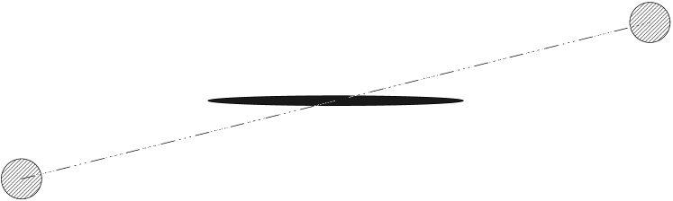
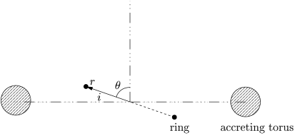
Following JB99, our simulations include three distinct mass components: a disc, a halo, and an accreted torus. The plane of the torus is inclined to that of the disc, as sketched in Figure 1.
Our simulations are set up as follows: The initial disc has the exponential surface density profile:
| (1) |
where is the cylindrical radius and and are the scale radius and the total mass of the disc, respectively. We truncate the disc at , spread the particles vertically as the isothermal sheet with a locally-defined equilibrium vertical velocity dispersion, and embed it in the halo; the rms vertical thickness of the initial disc is at any radius. We set the initial velocities of the disc particles such that the Toomre stability parameter and the disc is in rotational balance.
The halo is set up so as to be in equilibrium with the disc using the procedure described in Appendix A of Debattista & Sellwood (2000). The distribution function has a King-model form with , where is the central velocity dispersion and is the relative potential at the centre (Binney & Tremaine, 1987), which in our case includes a contribution from the disc. We set the tidal radius , and total mass . The King radius is and the half-mass radius of the halo is . The inner halo is mildly oblate initially due to the gravity of the disc. The halo we adopted here is massive, as we attempt to use a similar halo profile used by JB99 in which for . Other experiments with halos having different mass profiles, to be reported elsewhere, have revealed that the conclusions presented here are not strongly affected by the choice of halo; warping behaviour is less sensitive to the density profile or total mass of the halo than to the masses and sizes of the disc and torus.
Following JB99, we gradually inject particles into an inclined torus, causing its mass to increase linearly from 0 at , to at . The torus, which has radius , is uniform in azimuth and has Gaussian density profile in cross-section, with a standard deviation ; in our case, and . The torus plane is inclined at relative to the initial disc plane and we adopt the line of nodes as the -axis of our coordinate system.
The initial velocities of injected torus particles are equal to the local circular speed in magnitude and directed tangentially around the torus, as in JB99. Thus the torus has very large angular momentum, and therefore does not precess significantly from its original plane in response to the torque from the disc. However, a cold torus is dynamically unstable and breaks into radially extensive spiral filaments after a few Gyrs when allowed to evolve self-consistently. The breakup of the cold torus depends on many factors that we do not fully understand — e.g., tori with the same parameters dissolve differently and at different times in runs with rigid and live halos. In order to avoid the inconvenient complication of time-varying, non-axisymmetric perturbing forces acting on the disc, we generally keep the torus particles fixed in their initial positions relative to the galactic centre. This stratagem enables us to compare the dynamical evolution of warps in different experiments with the same torus parameters.
All 1.25 million particles belonging to massive components in our simulations have equal masses.
We adopt and as our units of length and mass, respectively, and our time units are therefore dynamical times . Generally all quantities are expressed in units such that unless otherwise noted. These units can be scaled to physical values as desired; we adopt one possible scaling, choosing kpc and a unit of time of Myr implies ; our unit of velocity scales to 244 km s-1.
We use the hybrid particle-mesh scheme described in detail in Sellwood (2003, Appendix B). The self-gravity of the disc is computed on a high-resolution cylindrical polar grid (see Sellwood & Valluri, 1997; Shen & Sellwood, 2004), while that of the halo is computed using a surface harmonic expansion on a spherical grid. We have carefully checked that the preferred plane of the cylindrical polar grid does not introduce artificial forces between a tilted disc and the grid, which requires a fine polar grid. Our adopted numerical parameters are summarized in Table 1.
| Cylindrical grid | Spherical grid | |
| Grid size | ||
| Angular compnts | ||
| Outer radius () | 8.0 | 18.0 |
| -spacing () | 0.02 | |
| Softening length () | 0.02 | |
| 0.1M | 0.9M | |
| Time step | 0.04 | 0.04 |
Over a period of 400 dynamical times, energy is conserved to about 0.02%, angular momentum components (, , ) change no more than 1%, and the absolute change of linear momenta (, , ) are less than 0.06 in units we adopted. Without the misaligned torus, these global integrals are conserved with a precision almost one order of magnitude better.
Our main warp diagnostic is the tip-LON diagram introduced by Briggs (1990). We construct it from an analysis of the disc particles, which are binned into annuli. The inner disc is very stiff and remains very closely coplanar within the innermost ; we therefore use a single bin for all particles inside this radius and adopt cylindrical bins (spherical bins are preferred if run for a very long time) of equal radial widths outside this radius to . (The bins remain aligned with the original disc axes.) We then compute the eigenvectors of the inertia tensor to determine the orientation of the disc element, and in each bin. We use the orientation of the inner bin to define the plane of the inner disc. We have experimented with various bin widths and found this binning scheme gives us the best compromise between spatial resolution and noise in estimation of the disc orientation (especially for thicker/“hotter” inner discs). We describe the diagram and its meaning in §3.3.


3 A canonical simulation
Without the torus, the disc in our model heats mildly; rises from to over 300 dynamical times, the disc thickens by and, of course, shows no signs of warping. The virial ratio stays at 0.5, confirming the equilibrium of our initial model. The disc remains unbarred until very late times.
We grow the inclined torus in our canonical experiment, in which the initially thin and flat disc experiences a growing torque. Since the disc is spinning rapidly, it tends to precess about the symmetry axis of the distant torus; differential precession will make the disc warp. We present a quantitative discussion of the precession in §4. The much larger moment of inertia of the accreted torus implies that its precession in response to the torque from the disc is minimal, and we therefore keep the torus particles frozen in their initial positions relative to the galaxy centre in order to provide steady forcing. Some differences in the disc behaviour between this case and one in which the torus particles move begin to appear after .
3.1 Morphology of warps
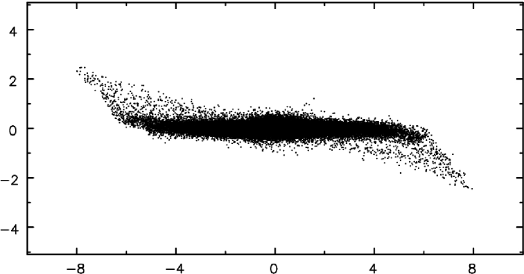
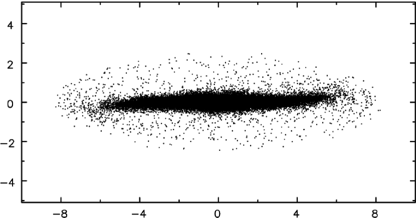
Figure 2 shows the edge-on projection of the warped disc in the canonical simulation at , or dynamical times after torus growth ended. To reveal the warp more clearly, we have rotated the particle coordinates to the frame of the inner disc.
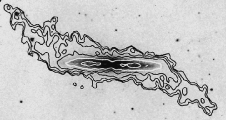
To illustrate that the warp in our simulation indeed resembles those observed, we compare it to the strongly warped hydrogen layer of NGC 4013 (Bottema, 1996). The correspondence is not perfect; e.g., our simulated warp starts at around whereas the warp of NGC 4013 starts to develop at the edge of its optical disc, about (Bottema, 1996). We could adjust the density profile of the halo, which affects the radius at which the disc starts to warp, but have not attempted to tailor our model to improve the match.
Note also that the particles in our simulation are collisionless whereas the warp is observed in the dissipative gas component. Nevertheless, the comparison should be reasonable because the precession rate of the simulated warp is low – collisional dissipation in a gas layer becomes important only when the differential precession rate is high (Gunn, 1979; Tohline et al., 1982). Furthermore gas often condenses into very compact clouds, which behave quasi-ballistically in a similar manner to a stellar system (Binney, 1992).
3.2 Warp angle
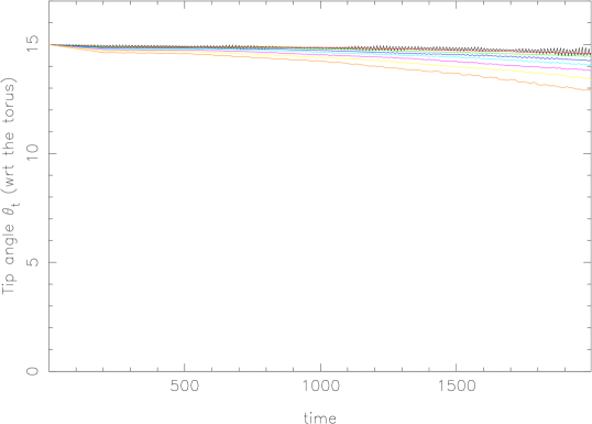
Figure 3(a) shows , the tip angle relative to the -axis of the initial disc, at various times. In Figure 3(b) we transform to warp angles , which are measured relative to the orientation of inner disc () at each time. The warp amplitude at later times in Figure 3(b) seems to compare well with that in NGC 4013, both visually and quantitatively (cf. Bottema, 1996, Figure 6).
3.3 LON of the warp is a leading spiral
Consistent with our convention for warp angles, we use for the azimuth of the line of nodes between the plane of the inner disc and that of the annular bin, and for the corresponding line of nodes with the initial unperturbed disc plane.
Figure 4 shows the evolution of LON of the warp, in the form of tip-LON plots (Briggs, 1990). The points (small open circles) indicate the angle (, ) of the symmetry axis of an annulus of disc material, relative to the inner disc plane at any given time. The radial coordinate is the warp angle (inclination), , and the azimuthal coordinate indicates the azimuth, , of the best-fit plane to a disc annulus. Points at successively larger ring radii are joined sequentially by straight line segments. Note that since the warp angle, , increases with radius (Figure 3), the plotted points refer to radially ordered annuli from the centre out.
Figure 4 shows that the LON of the warp precesses in the retrograde direction, while curving gradually into a leading spiral (i.e., the LON advances in the direction of galaxy rotation for successively larger radii), consistent with the third rule of Briggs (1990). We have run many other experiments with various parameters and found that the LON to always forms a leading spiral when the disc is perturbed by an outer inclined torus. The reason for the leading spiral is explained in detail in the next section (§4). Also the LON is fairly loosely wound throughout our simulation. Bottema (1996) concluded that the LON of NGC 4013 winds modestly, by about , which is consistent with that in our simulated warp, in addition to the nice visual resemblance in Figure 2.
4 In-depth analysis on the shape of LON
Since there are many factors that affect the warp morphology, we break the dynamics into parts. We first study the simplest aspect analytically, and then gradually add in separate pieces of the physics to illustrate their effects. These simplified experiments are very helpful for developing understanding of warp dynamics and the reason for the curved LON. We stress that our adopted massive torus at a very large radius has so much angular momentum that its precession due to the torques from the disc and flattened inner halo can be neglected.
4.1 A test particle disc in a rigid halo
We first study a very simple model, in which the halo is both rigid and spherical. We also replace the self-gravitating disc with massless test particles and represent only the torus with massive particles. This model is sufficiently simple that the behaviour can be predicted analytically and provides a welcome check of our numerical code. We expand the potential of the distant torus as a series of multipoles and calculate the disc precession rate analytically, both to second- and to fourth-order, in Appendix A; we give exact formulae for and in Appendix B.
We use test particles to represent the massless disc and adopt a rigid, spherical King-model halo with , , and total mass . Only the torus is composed of massive particles, and is grown from to within time units, as before. The inclination angle of the disc with respect to the plane of the accreting torus is .
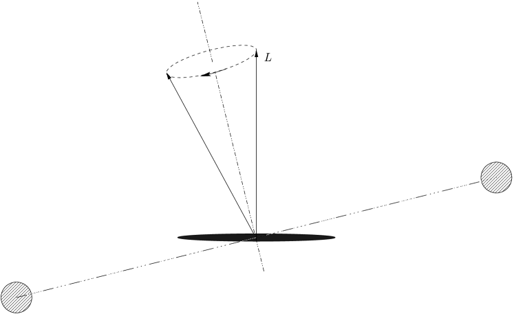
The disc is composed of many concentric rings of massless particles, which precess at fixed inclination in a retrograde fashion under the torque of the distant accreting torus. The precession is illustrated in Figure 5.
We use the following notation: is the nodal precession rate of a narrow annulus of the disc at radius ; is the angle between the symmetry axis of this annulus and the -axis (i.e., the normal to the initial unperturbed disc); is the azimuthal angle of the symmetry axis of the annulus projected in the - plane, which is the plane of the initial unperturbed disc.
Each annulus precesses through an angle
| (2) |
where the precession rate due to the quadrupole term only (Equation 21) is
| (3) |
Clearly increases with .
For test particles at a given radius, the tip angle and can be measured from the orientation of their angular momentum vectors. The angles, and , measured from particles at two distinct radii are shown in Figure 6; each particle in an annulus has its own pair of angles at each instant, which vary systematically with phase giving rise to the spread. The mean is in qualitative agreement with these second-order predictions, shown by the dashed curves while the fourth order (Equation 20) predictions (solid curves) agree very well. Since can have any value when , we set to for , to suppress noise in these figures.
The increasing rate of retrograde precession with radius causes the warp angle and to increase outwards also. We observe this behaviour in our test-particle simulation as shown in Figure 7. In this simplified model, the warp appears as the result of the differential precession and the LON forms a trailing spiral.
This simulation also serves as a nice check of parts of our numerical code: forces from the torus particles and the time integration of the test particle disc are calculated accurately.


4.2 Including disc self-gravity
We separate a self-gravitating disc into an inner disc and an outer disc. The dense inner disc, which contains most of the disc mass, tilts rigidly as a whole; it is strongly coupled together due both to self-gravity and to radial velocity spread of stars, which communicate stress across the disc via epicyclic excursions (Debattista & Sellwood, 1999). The gradual locking of the disc due to self-gravity was also found in Lovelace (1998). The low-density outer disc, on the other hand, is much less cohesive because self-gravity is weak and epicycles are small; the outer disc behaves more as a collection of test particles therefore.
As the torus mass rises, the whole disc starts to precess as described in §4.1. The torque from the torus causes the inner disc, which is strongly cohesive, to precess slowly as a whole in a retrograde manner about the symmetry axis of the torus, while the outer disc precesses more rapidly. The developing misalignment between the inner and outer disc causes the particles in the outer disc to feel an additional torque from the massive inner disc. The rate of precession of the outer disc due to the torque from the inner disc follows a different rule from that due to the torus.
The disc potential at larger radii can be approximated as the sum of a monopole and a quadrupole term (Binney & Tremaine, 1987, Equation 6-84),
| (6) |
Using equation (1) for an exponential disc, we have
| (7) |
In the same manner as for the torus (Appendix A, see also Kahn & Woltjer, 1959; Gunn, 1979), we find the precession rate of test rings due to the disc is
| (8) |


While still producing retrograde precession, the rate from this additional forcing term varies with radius in the opposite sense of that from the torus. In the case of forcing by the inner disc, the precession rate Equation (8) decreases with increasing radius, which in isolation would tend to make the LON develop a leading spiral.
The outer disc is now subject to two torques, from the torus and from the inner disc, both of which cause retrograde precession, but at rates that vary radially in opposite senses. Whether the resulting spiral in the warp LON should lead or trail over the range of interest depends on relative magnitudes of the torques, and is best determined from simulations.
We have therefore performed a series of simulations with increasingly massive discs to show that the torque from the inner disc dominates in our canonical simulation, which develops a leading spiral in the LON (see Figure 4). Figure 8 presents the tip-LON diagrams from four experiments with increasingly larger disc masses (from to ) to demonstrate the effect of the disc mass. These experiments continue to employ the same spherical rigid halo and torus parameters as above. The general trend confirms that the leading spiral gradually dominates the inner LON as is increased; the LON has become completely leading in Figure 8(d) where . (Note that the result for in a rigid halo differs from that in Figure 4 where the halo is responsive.)
4.3 A test particle disc in a live halo
The rigid spherical halo in the above experiments, cannot respond to the precessing disc, and therefore does not affect how the LON curves. A halo composed of live particles should acquire a distorted shape in response to the fields of the torus and the disc. These effects are both included in a fully self-consistent simulation. Here we study these effects separately and demonstrate that the live halo does not alter the conclusions we reached in §4.1 and 4.2.
In a further experiment, we replace the rigid halo in the model of §4.1 with a live one with nearly the same potential. Figure 9 shows that in this experiment the LON becomes trailing, as we found in §4.1 where the halo is spherically rigid. This again supports our argument that the massive disc, instead of other factors like a live halo, is the primary reason why the LON forms a leading spiral for warps induced by cosmic infall. The small differences in the angle of precession between Figures 9 and 7(b) indicate that the oblateness of the halo (induced by the torus) contributes only slightly to the precession of the disc.
We discuss the response of a live halo with a massive disc in §5.


4.4 Spirality twist of LON at large radius
In Figure 8(c), we can clearly see the spirality of LON twists from leading to trailing in the tip-LON plot at . Here we show that such spirality twist is a generic feature for warps caused by an external quadrupole field giving outward-increasing rate of retrograde precession.
As shown above, the sense of spirality of the LON is determined by the radial variation of the precession rate , and is measured by in the tip-LON plots. From Equation 2 and 5, we have
| (9) |
the negative sign indicates that the precession is retrograde. Whether the spiral leads or trails depends on whether falls or rises as increases, as illustrated in Figure 10.
We have argued that the torque due to the massive inner disc, which causes to dominate, causing the leading spiral found in our simulations. Beyond some critical radius, , precession is dictated by the accreting torus, , and a trailing LON should be expected. The critical radius can be estimated as follows: The magnitude ratio of the torques exerted on a test ring at radius , due to the torus (the first term of Equation 19 as the second-order approximation) and to the massive inner disc (Equation 8), is approximately
| (10) |
The radius of the spirality twist is approximately where
| (11) |
So we have
| (12) |
For our torus parameters (, ), we find . In Figure 8(c) where , the spirality twist occurs near the sixth point from the centre (i.e., near the annulus centered on ), so it agrees well with the expected .
can also be understood in the context of a Laplacian surface, where the net torque vanishes (Binney & Tremaine, 1987, chap. 6.6). It is easy to show that is also the transition radius of the Laplacian surface; for , the Laplacian surface almost coincides with the inner disc, which dominates the precession for small radii, while for , the Laplacian surface follows the equatorial plane of the torus, which dominates the precession at large radii.
The inner part of a responsive halo becomes oblate due to the massive inner disc. The co-aligned oblate inner halo adds significantly to the torque from the inner disc, causing to be larger than estimated above, to perhaps . So the LON spirality twist could occur at radii .
Thus the spirality twist can be seen only if there is a tracer at very large radii. We do not see the spirality twist in Figure 4 because very few particles lie beyond . To reveal the expected spirality twist, we add into our canonical simulation 20,000 massless test particles in the radial range of , to mimic the outer gas layer. We used 14 radial bins to cover all particles; the binning scheme is similar to that described in §3.3. The spirality twist shows up in Figure 11 near the seventh from outermost point (i.e., near the annulus centered on ). As expected, the spirality twist grows more pronounced with time.
Note that a twist can occur only if the forcing causes an outward-increasing rate of retrograde precession, as for our simplified torus. More realistic perturbations may not have this effect.
5 The halo response
In this section, we return to our canonical simulation (§3) with the live halo and the massive disc ().
5.1 Disc–inner halo alignment
Figure 12 shows the orientation of the halo in three spherical bins (, , and ) measured from the canonical simulation. The inner halo (heavy line) follows the inner disc (dashed) closely, while the outer halo (light line) quickly aligns with the outer torus, which has a tip angle and azimuth . The halo orientation in the middle bin is intermediate. It is worth stressing that the halo mass interior to is almost five times that of the disc, yet its orientation does not follow that of the outer halo and massive torus, but instead follows that of the lighter disc, which precesses around the axis of the torus because of its angular momentum. Because the massive inner halo is oblate and aligned with the inner disc, it adds significantly to the precession and curving of the LON in the outer disc. Binney et al. (1998) also found that the inner halo quickly realigns with the disc, even when a large initial misalignment is imposed.


5.2 Halo damping
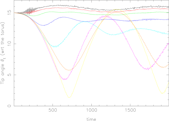
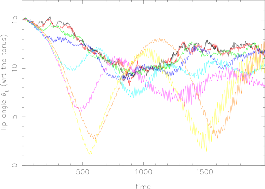
Figure 13 shows that halo damping of the warp by the live halo is weak. Now for the convenience of description, we name the canonical run as “Run CL” (i.e. canonical run live halo). We introduce “Run CR” (i.e. canonical run rigid halo) with the almost same halo potential222Note that the two potentials cannot be exactly the same, because the live halo is slightly oblate due to the gravity of the disc initially, and its oblateness evolves with time. as in the canonical run except that the halo is rigid and stays exactly spherical. Panel (a) shows that nested rings of test particles on circular orbits in a rigid halo precess at constant inclination, , to the plane of the torus. Since rings precess at different rates, the apparent deviations from at later times are caused by averaging rings with the same inclinations, yet different azimuths, over a finite radial range. (We have verified that the inclinations of individual particles with respect to the torus plane indeed remain close to , as expected.) Panel (b) shows that self-gravity in a massive disc causes differential precession about the axis of the inner disc (Run CR). The quasi-periodic modulation of the inclinations of the outer rings in (b) is a manifestation of the extra torque from the inner disc. The initial decrease of the inclinations of most annuli to the torus plane (between and 600) has nothing to do with dynamical friction or halo damping since the halo is rigid in this case. The final panel, (c), shows the effect of using a live halo (the canonical Run CL). The precession due to the disc is augmented by the aligned flattening of the inner halo, which is partly responsible for the differences from panel (b), but a full explanation of all the details in this Figure is complicated; e.g., we would need to take into account the inclination of the halo at intermediate radii. The important result is that even after 2000 dynamical times, the mean inclination of the inner disc to the torus has not decreased by more than ; i.e., damping from the live halo is very weak.
Our result differs from the conclusions of Dubinski & Kuijken (1995) and Nelson & Tremaine (1995) because the scenarios studied are different. Their models have a very large initial misalignment between the halo and the inner disc and a significant precession rate calculated according to the “modified tilt mode” in Sparke & Casertano (1988). Another difference is that the halos in their models were given no time to adjust to the strong and rapidly-precessing warp initially inserted in.
In our simulations, the precession rate of the inner disc is very low, and the inner halo follows its motion closely, as shown in Figure 12, which is why dynamical friction between the two components is negligible. Only the outer halo is misaligned and damping comes mainly from coupling between the inner and outer halo. Such coupling is weak for the isotropic halo models we used (Nelson & Tremaine, 1995). This is also consistent with the recent cosmological hydrodynamical simulations by Bailin et al. (2005), which found that the relative orientations of inner () and outer () halo are uncorrelated.
6 Discussion
6.1 The source of the external torque
The torque in our model arises from a uniform, massive torus centered on the galaxy and inclined to the disc, as originally adopted by Jiang & Binney (1999). The warp is driven by the quadrupole field of the torus, which varies as , and therefore a less massive torus at a smaller radius has a similar effect, as we have verified in other experiments. However, a weaker perturbation would give rise to a milder warp that would take longer to form.
A natural direct interpretation of the torus is an idealized representation of the stream of stars and dark matter from a disrupted orbiting satellite, if the mass is sufficiently large. There are numerous examples of accreted satellites, or companion galaxies orbiting in planes that are misaligned with that of the disc of the host galaxy. The Sgr Dwarf and the Magellanic Clouds are clear examples in the Milky Way, but their masses are generally on the low side unless their halos are substantial.
On the other hand, the torque from the torus is similar to that of a flattened outer halo, which may also have misaligned angular momentum (Quinn & Binney, 1992). Conceptually, one could separate the halo into two mass components: an outer halo flattened in a plane misaligned with the disc and having a uniform, quasi-spherical core, and the remainder – an inner halo with any arbitrary radial mass profile, that may be strongly peaked to the centre of the galaxy. Regardless of how flattened the inner halo may be, it exerts no torque on the inner disc, since it is generally aligned with the disc plane (see §5). In this picture, the gravitational potential of the outer oblate halo alone might approximate the form: , which arises from a flattened isothermal envelope with a quasi-spherical, uniform core of radius , with a density scale set by . The ellipticity of the equipotential surfaces is approximately , where is the ellipticity of the halo density. It is easy to show the torque due to this outer halo exerted on a ring in the disc at radius is , which has the same radial dependence as the torque of a uniform torus. The effects discussed in §4.4 and §6.2 are dependent on the outward-increasing rate of retrograde precession of our model. The torque from our adopted torus is of the same order of magnitude as such an outer halo with a typical flattening in the range depending on .
Cosmological simulations that include baryonic infall have not yet settled on a set of robust predictions for the shape and alignment of the outer halo. A misaligned potential of the form just described is highly idealized, but has served as a useful theoretical exercise to understand warps. It has yielded some insight that may capture features of the torques that drive real warps.
6.2 Persistence of warps
The windup rate of a warp depends on the radial variation of the net precession rate. (The amount of the windup can be measured by , see Binney & Tremaine 1987.) Forcing by our adopted torus causes differential precession of the opposite sign from that of the disc, making the total retrograde precession less differential, especially in the warp region (). Thus the stiff inner disc and the two precessions work together to slow the windup of the warp.
However, it is more interesting to study the evolution of a pre-warped massive disc without any external forcing. We therefore conducted two further experiments in which we removed the forcing torus after some evolution. We ran cases with both live (CL–torus) and rigid (CR–torus) halos, derived from the canonical runs CL (live halo) and CR (rigid halo). In both cases, we gradually removed all the torus particles in a linear fashion between and after which, no torus particles remain. (Note that in all runs the torus mass was grown linearly to its maximum between and 200.)
In these two runs, a warp was already well developed by . Ramping down the torque from the torus allows us to study the unforced behaviour of the warped disc. In run CR–torus, the disc is affected by its self-gravity only (because the halo is rigidly spherical), but in run CL–torus, the effect of self-gravity of the live halo is also included.
In Figure 14 and Figure 15 we compare the LON between runs in which the torus was left in place and the cases in which it was removed. Figure 14 shows the two cases at for the rigid halo, and Figure 15 shows the corresponding two cases with the live halo. Note that both experiments in each pair are identical at . Two results are evident from this comparison, regardless of whether the halo is rigid or live: first, the amplitude of the warp is little changed by the removal of the forcing torus confirming that damping from the halo is weak; second, the LON in runs with the torus removed is more wound than in runs where the torus remains. This second point confirms that the torque from the torus is important to balance out the differential precession due to the stiff inner disc, and reduces the windup rate of the warp, but the extra winding is mild even Gyr after the torus starts to be taken away. Thus the warp can persist for a few Gyrs after the imposed quadrupolar perturbation is removed.


6.3 Observations of the LON at large radius
Our analysis has shown that the LON of warps in the inner region forms a leading spiral due to the potential of the disc and inner halo. The fact that the LONs of most warps form leading spirals over an extended radial range may also imply that the disc mass is significant in the central region of these galaxies (e.g. Figure 8).
The spirality of the LON at larger radii, on the other hand, contains information on the mass distribution in the outer halo that drives the warp. For example, if warps are formed by external perturbations that exert torques of the form of our adopted torus, the LON should twist from leading to trailing at some large radius. The absence of a twist would imply a perturbation of a different form.
We have looked for signs of a twist in the largest sample of galaxies with tip-LON data to date (Briggs, 1990). The transition radius for the torus we study (§4.4), a value that has a mild dependence on the torus properties (). If most of the large, late-type spirals in Briggs’s sample have Holmberg radii in the range , we expect and we therefore examine those having LON data beyond .
Six galaxies (NGC 628, NGC 5055, NGC 2841, NGC 1058, NGC 3344 and M83) in this sample have LON data outside . We find that NGC 628 and NGC 5055 show signs of the LON spirality twist near ; NGC 2841 and NGC 1058 show weak signs of the spirality twist; the LON of M83 is quite straight near , and might have spirality twist at an even larger radius; the LON of NGC 3344 is very noisy, but the spiral of the overall LON trend does not seem to twist. Thus perhaps four out of six galaxies reveal hints of spirality twists in their LONs.
Thus currently available data do not provide convincing evidence for the spirality twist, mainly because the LON data beyond (Briggs, 1990) are generally sparse and noisy. The outer morphology of the LON is worth more detailed investigation in deeper HI 21 cm observations of gas-rich galaxies, since it may contain valuable information on the shape and profile of the mass distribution in the outer halo.


6.4 The apparent thick disc due to warping
The intrinsic thickness of the disc about its mean inclination is not greatly increased by warping. Comparison of the three panels in Figure 16 reveals that the evolution of the disc thickness is little affected by an aligned torus, and a tilted torus causes only a slight increase for .
But a warped, luminous disc will contribute some light outside the thin, inner disc which, from some viewing directions (see Figures 17), may resemble a low-surface brightness thick disc. Suppose an idealized warp that starts from at an angle to the inner disc and has a straight LON. (We define to be the kink angle between the flat inner disc and the steepest edge of the warp when seen in projection along the LON, i.e. it is not the warp angle defined above.) The projected surface brightness profile along the minor axis of the edge-on disc will clearly be exponential with vertical scale-height , and its brightness is roughly . The angle for the warp in Figure 2a and Figures 17. Thus, if the warp starts in the luminous disc, it could possibly affect conclusions about thick discs from photometry of edge-on galaxies.
7 Conclusions
Now that the role of a live halo has been properly taken into account, the idea that galaxy warps are manifestations of long-lived warp modes appears to have reached a dead end. But warps as responses to external forcing remain viable, provided that suitable perturbations are frequent enough. Hierarchical galaxy formation scenarios guarantee late infall within gravitationally bound subgroups, both diffuse and in lumps, and the infalling matter is unlikely to share the angular momentum vector of the early disc and halo (Ostriker & Binney, 1989; Quinn & Binney, 1992).
The simulations presented here are motivated by this idea, but are limited to an in-depth study of one highly idealized case. We examine how an initially flat particle-disc with random motion, embedded in a live halo, gradually acquires a warp as a result of a steady, applied external torque. Rather than striving for realism, we have endeavoured to understand how the warp develops and why the LON generally forms a loosely-wound, leading spiral.
Despite having focused mainly on one case, we find a long-lived, large-amplitude warp that resembles those observed in many respects. The disc is flat in the inner part, and starts to warp at into an open leading spiral, which is consistent with the warping rules found by Briggs (1990).
The external torque causes the disc to precess in a retrograde sense. The warp develops because the precession rate of the inner disc, which is strongly cohesive due to its self-gravity and random motion, is slower than that of the outer disc. The growing misalignment between the inner and outer disc gives rise to a new torque acting on the outer disc from the massive inner disc, and the inner halo that is coupled to it. The torque from the interior mass is responsible for the leading spiral of the line of nodes – our adopted external field alone would produce a trailing spiral. The fact that the LON of most warps forms a leading spiral over an extended radial range seems to imply a massive disc (e.g. Figure 8).
On the other hand, the leading spiral tells us little about the cause of the warp, but such information might be revealed by the behaviour of the warp at large radii. We show that the LON twists to trailing at very large radii from our experiments with a perturbation that alone would cause the warp to form a trailing spiral. Thus better observational data on the shape of the LON at very large radii may reveal the radial dependence of the torque that created the warp, and thereby provide information on the shape of the halo at large radii.
Because the two separate components of the torque in our model cause differential precessions in opposite senses, the net retrograde precession of the warp is less differential than when only one is present. The moment we removed the external torque, the warp began to wind, although its amplitude did not decrease. Thus the quasi-steady warp we observe that lasts for more than a Hubble time is a consequence of steady external forcing.
Even though the disc precesses due to the external torque, its motion is hardly damped over many Gyr, in contrast to the expectations from Nelson & Tremaine (1995). Damping is weak because the slow precession rate allows the inner halo to remain closely aligned with the disc, which therefore causes little drag. The very weak damping seems to be caused more by the relative precession of the inner and outer halo.
A fixed outer torus is clearly unrealistic and external forcing is likely to be strongly time-dependent in reality. We cannot say much about the rate at which misalignments in real halos will settle, but we have shown that the warp survives for a few gigayears after the torus is removed. Time dependence may anyway be a side issue if the halo axis is constantly slewing, as argued by Quinn & Binney (1992). Warps formed this way can be repeatedly regenerated when a new infall event happens. Since cosmic infall and mergers are more likely to happen in a denser environment, warps can be induced more frequently in such an environment, which is consistent with the warp statistics in García-Ruiz et al. (2002).
Since warps are ubiquitous and a gravitational phenomenon closely related to hierarchical galaxy formation, their properties may possibly be able to constrain small-scale cosmic structure. Clearly further experimentation with various external perturbations, halo profiles and masses, disc properties (random motions, barredness), etc., is required to discover what might be inferred from the existence of warps in galaxies.
8 Acknowledgments
We thank Roelof Bottema for supplying the image used in Fig. 1. Stimulating discussions with James Binney, Alar Toomre, Scott Tremaine, and Victor Debattista have helped our understanding considerably. We also thank John Kormendy and an anonymous referee for helpful suggestions. This work was supported by NSF grants AST-0098282 and AST-0507323 to JAS and a Bevier Fellowship from Rutgers University to JS.
References
- Bailin et al. (2005) Bailin, J., et al. 2005, ApJ, 627, L17
- Binney (1992) Binney, J. 1992, ARA&A, 30, 51
- Binney et al. (1998) Binney, J., Jiang, I., & Dutta, S. 1998, MNRAS, 297, 1237
- Binney & Tremaine (1987) Binney, J., & Tremaine, S. 1987, Galactic dynamics (Princeton, NJ, Princeton University Press)
- Bosma (1991) Bosma, A. 1991, in Warped Disks and Inclined Rings around Galaxies, ed. S. Casertano, P. D. Sackett, & F. H. Briggs (Cambridge: Cambridge Univ. Press), 181
- Bottema (1996) Bottema, R. 1996, A&A, 306, 345
- Briggs (1990) Briggs, F. H. 1990, ApJ, 352, 15
- Cox et al. (1996) Cox, A. L., Sparke, L. S., van Moorsel, G., & Shaw, M. 1996, AJ, 111, 1505
- Debattista & Sellwood (1999) Debattista, V. P., & Sellwood, J. A. 1999, ApJ, 513, L107
- Debattista & Sellwood (2000) Debattista, V. P., & Sellwood, J. A. 2000, ApJ, 543, 704
- Dekel & Shlosman (1983) Dekel, A., & Shlosman, I. 1983, in IAU Symp. 100: Internal Kinematics and Dynamics of Galaxies, ed. E. Athanassoula (Dordrecht: Kluwer), 187
- Dubinski & Kuijken (1995) Dubinski, J., & Kuijken, K. 1995, ApJ, 442, 492
- Freeman (1970) Freeman, K. C. 1970, ApJ, 160, 811
- García-Ruiz et al. (2002) García-Ruiz, I., Sancisi, R., & Kuijken, K. 2002, A&A, 394, 769
- Gunn (1979) Gunn, J. E. 1979, Feeding the monster - Gas discs in elliptical galaxies (Active galactic nuclei. (A79-50785 22-90) Cambridge, Cambridge University Press, 1979, p. 213-225. Research supported by the Alfred P. Sloan Foundation), 213
- Hunter & Toomre (1969) Hunter, C., & Toomre, A. 1969, ApJ, 155, 747
- Jiang & Binney (1999) Jiang, I., & Binney, J. 1999, MNRAS, 303, L7
- Kahn & Woltjer (1959) Kahn, F. D., & Woltjer, L. 1959, ApJ, 130, 705
- Kuijken (1991) Kuijken, K. 1991, ApJ, 376, 467
- Lovelace (1998) Lovelace, R. V. E. 1998, A&A, 338, 819
- Nelson & Tremaine (1995) Nelson, R. W., & Tremaine, S. 1995, MNRAS, 275, 897
- Ostriker & Binney (1989) Ostriker, E. C., & Binney, J. J. 1989, MNRAS, 237, 785
- Quinn & Binney (1992) Quinn, T., & Binney, J. 1992, MNRAS, 255, 729
- Reshetnikov et al. (2002) Reshetnikov, V., Battaner, E., Combes, F., & Jiménez-Vicente, J. 2002, A&A, 382, 513
- Sellwood (2003) Sellwood, J. A. 2003, ApJ, 587, 638
- Sellwood & Valluri (1997) Sellwood, J. A., & Valluri, M. 1997, MNRAS, 287, 124
- Shen & Sellwood (2004) Shen, J., & Sellwood, J. A. 2004, ApJ, 604, 614
- Sparke & Casertano (1988) Sparke, L. S., & Casertano, S. 1988, MNRAS, 234, 873
- Steiman-Cameron & Durisen (1984) Steiman-Cameron, T. Y., & Durisen, R. H. 1984, ApJ, 276, 101
- Tohline et al. (1982) Tohline, J. E., Simonson, G. F., & Caldwell, N. 1982, ApJ, 252, 92
- Toomre (1983) Toomre, A. 1983, in IAU Symp. 100: Internal Kinematics and Dynamics of Galaxies, ed. E. Athanassoula (Dordrecht: Kluwer), 177
Appendix A The precession rate due to the torus
Suppose the disc is composed of many rigid rings (or annuli). Here we calculate the retrograde precession rate of one such ring, at radius and inclined relative to the torus symmetry plane with the angle , due to the potential of the accreting torus (see Figure 18).
The potential of the accreting torus (its thickness ignored) can be obtained as the following, by solving Laplace’s equation.
| (13) |
where is the conventional polar angle in the polar coordinate system based on the torus; and are the radius and mass of the torus, respectively.
We define
| (14) |
for convenience, so to the order of we have
| (15) |
The only force component relevant to the calculation of torque on the annulus is :
| (16) |
Since
we find
| (17) |
The torque exerted on a point mass in the rigid ring due to the torus depends on the azimuth of the point mass; the maximum value of the torque occurs at azimuth or where .
| (18) | |||||
The azimuthally average torque on the rigid ring is therefore
| (19) |
We can obtain the total retrograde precession rate due to the torus (up to the fourth order):
| (20) | |||||
For qualitative purposes, we generally use the following simpler second-order approximation (), unless the radius of the annulus is large.
| (21) |
Note that same results can be obtained for the nodal precession rate of a test particle’s circular orbit (as opposed to a rigid ring), the only difference here is that the average is taken as the time average over one orbit (the orbit-average procedure can be found in Steiman-Cameron & Durisen, 1984, Appendix).
Appendix B The derivation of tip angle of rings and azimuthal angle of their LON
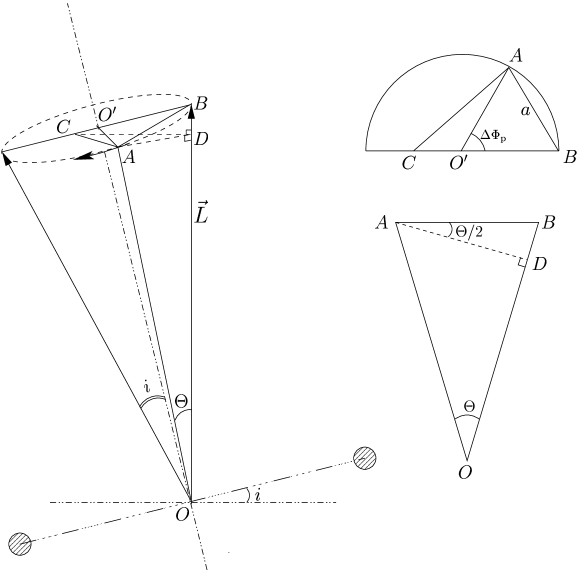
We first calculate the tip angle relative to the original -axis. We know . On the other hand we also have
| (22) |
here is angle that the annulus has precessed. So obviously the equation to determine is
| (23) |
If we define the azimuthal angle of the LON of a ring as the counter-clockwise angle from axis, . It can be shown, with some trigonometry on triangles in Figure 19, that
| (24) |
So
| (25) |
For small , we have
| (26) |