789\Yearpublication2006\Yearsubmission2005\Month11\Volume999\Issue88
later
Challenges in optics for Extremely Large Telescope instrumentation
Abstract
We describe and summarize the optical challenges for future instrumentation for Extremely Large Telescopes (ELTs). Knowing the complex instrumental requirements is crucial for the successful design of 30-60m aperture telescopes. After all, the success of ELTs will heavily rely on its instrumentation and this, in turn, will depend on the ability to produce large and ultra-precise optical components like light-weight mirrors, aspheric lenses, segmented filters, and large gratings. New materials and manufacturing processes are currently under study, both at research institutes and in industry. In the present paper, we report on its progress with particular emphasize on volume-phase-holographic gratings, photochromic materials, sintered silicon-carbide mirrors, ion-beam figuring, ultra-precision surfaces, and free-form optics. All are promising technologies opening new degrees of freedom to optical designers. New optronic-mechanical systems will enable efficient use of the very large focal planes. We also provide exploratory descriptions of “old” and “new” optical technologies together with suggestions to instrument designers to overcome some of the challenges placed by ELT instrumentation.
keywords:
Optics – ELTs – spectrographs – gratings – new materials1 Introduction
Extremely Large Telescopes (ELTs, ground-based telescopes between 20m and 100m in diameter, i.e. substantially larger than any currently operating facility) are desired by Astronomers mainly because of the urgent need of spectroscopic support for future space facilities such as the James Webb Space Telescope (JWST). Instruments on-board JWST will reach magnitudes that require much larger collecting areas to perform spectroscopic follow-up than any telescope currently operating. Even today the Advanced Camera for Surveys on the Hubble Space Telescope has already produced images of a depth far exceeding the ability of current telescopes to acquire useful spectra, with the exception of objects having strong emission lines.
Apart from space facilities follow-up, ELTs will be breakthrough astronomical facilities in their own right, able to tackle problems such as the nature of first-light objects, the evolution of large scale structures in the early universe and of the chemical composition of the intergalactic medium, the assembly of galaxies at high red-shifts and the traces of this process today, the formation of stars and planetary systems, the detection and characterization of extra-solar planets, possibly down to terrestrial sizes, and detailed synoptic studies of objects in our own solar system. Detailed science cases for ELTs have been published, amongst others, by Hawarden et al. (2003).
Europe is putting a lot of effort, both at research institutions and at industry level, to pursue a feasible configuration for an ELT. Two preliminary designs exist and are currently debated in the community: the ESO 100 or 60-m OWL (OverWhelmingly Large) telescope (Dierickx et al. 2003) and the 50-m aplanatic Gregorian named Euro50 (Andersen et al. 2003). On the American side three original proposals for extremely large telescopes exist; the GSMT (Giant Segmented Mirror Telescope), the Canadian VLOT (Very Large Optical Telecope) and the CELT (California Extremely Large Telescope). The latter two were recently merged into a single TMT (Thirty Meter Telescope) project.
All these facilities are expected to be operated in seeing-limited conditions and in diffraction-limited conditions (Strehl 0.2-0.5 over field of view of arcminutes via MCAO correction). In seeing-limited conditions a telescope of diameter [metres] and focal ratio , a point source with FWHM of the image PSF [arcsec], is recorded with a width in [microns] given by
| (1) |
where the width is indicated as the dimension of the individual pixel multiplied by the number of pixels . Although the telescope’s optical design is under study, it is very unlikely that a solution with will be found. In the case of seeing-limited applications and assuming the limit case , a median good-site seeing of 0”.6, observed with a 100-m telescope would produce a 293m spot. This has two immediate consequences: a) The focal plane of ELTs will be very large in size, b) current detector pixel dimensions (10-20m), if used in this context, provide heavily over-sampled images. One could accept such an over-sampling if it were not for the problems of cost and procurement. One could also encourage the development of larger pixel detectors. Since read-out noise is generally proportional to pixel area, there is a price to pay in terms of sensitivity, specially in detector limited applications such as high resolution spectroscopy. More importantly, the development and production costs of such devices would be prohibitive.
The problem of étendue, driving the plate scale on the telescope focal plane, can be solved by dividing the pupil between several instruments. Six or 7 sub-pupils of 30m each can be obtained out of a single 100-m pupil at the price of a limited waste of aperture. Each of the sub-pupils would be identical to a stand-alone facility of the correspondent size. If one wishes to fully exploit the depth reachable with a 100-m pupil one will have to manufacture 6-7 identical instruments for a 30-m pupil and then coadd the signals. On the contrary, if the pupil division system is specially designed for this purpose, each of the subpupil could feed instruments with different characteristics allowing one to cover simultaneously, albeit at a more limited depth, a larger set of physical parameters, e.g. different polarizations, wavelength, etc.. The above schemes require to plan a limited series production of instruments traditionally conceived as single units, assessing the problem of high reproducibility of identical components specially in optics, mechanics, detectors, etc..
Even in the divided-pupil option, the extreme focal ratios which are required for instruments operating well away from the telescope diffraction limit raise the issue of weight. Traditional optical components with strong curvatures are invariably massive for their size. In addition, any intermediate optical stage is likely to be an order of magnitude slower so that FoV and optical elements will have to be large, typically 1m for a 30-m telescope (or sub-pupil) and 3m for a 100-m facility. Apart from manufacturing challenges, this implies physically large instruments which could not always be compatible with the ELT mechanical structure.
Most ELTs are designed to work with Adaptive Optics systems. Much effort is currently devoted to the development of wide-field high-performance AO systems capable of delivering Strehl ratios of 20-50% over fields-of-view of arcminutes instead of arcseconds. There are various technical approaches aimed to deliver the same results, including MCAO (Multi-Conjugated Adaptive Optics). A 30-m telescope with a near diffraction-limited FoV of about 2 arcmin at a wavelength of 1 m yields about 3108 resolution elements each of about arcsec in size. A billion pixel detector is needed to sample properly such a small area, to be compared with the 4k4k currently available on the market for these wavelengths. For a 100-m telescope the situation is about one order of magnitude more difficult. The only solution in this case is a system to pick-off sub-fields for full resolution observing, i.e. divide the focal plane. In the diffraction-limited regime the pick-off is determined by the plate-scale achievements and is common to any kind of instrument willing to exploit the full capability of MCAO.
In order to address the technology improvements needed to face the phase of ELT-instrument design and manufacture, a workshop was jointly organized by the Italian National Institute of Astrophysics (INAF) and the UK Astronomy Technology Centre (UKATC), under the auspices of the OPTICON Key Technology Network. This workshop joined together European institutes and industries for a brainstorming discussion about problems and possible solutions. Its key issues, main summaries and preliminary conclusions are presented in this paper.
2 Large optical components
2.1 Summary of requirements for large optics
The Extremely Large Telescopes (TMT, LSST, European ELT) and their instrumentation will require large optical components: mirrors, lenses, filters, and gratings, with very stringent specifications. We review the requirements in large optical components featured in some of the ELT instruments. This includes the specifications of the optical materials in terms of homogeneity and stability in index of refraction, polishing errors and anti-reflection coatings. Issues concerning the mounting of these components at various environmental conditions must be addressed. For each effect we will explore implications and possible new areas of technology development.
2.1.1 Optical blank specifications
Clear Aperture Diameter. For BK7, Fused Silica, and FK5 we will possibly need 1.2m to 2m. These will be used mainly for windows, field correctors, ADCs. In the IR, materials such as BaF2, CaF2, ZnS, ZnSe are very popular in cameras and collimators. Can we break the boundary of the limited size we can order from optical industry? At present, we can find these materials at a diameter of 200mm to 500mm. In the sub-mm (250, 450 and 850m wavelength), the only transparent materials used are in polystyrene or plastic materials. We will need windows of 1 m, filters of around 300 to 500mm, dichroics around 200mm diameter.
Homogeneity. Some of the materials will be required to have 10-7 for 1 m diameter and 60mm thickness. At present 10-6 can possibly be achieved for special homogeneous materials. The measurement of homogeneity for large pieces is an issue: at present only 500mm can be measured (“Schott Direct Measuring Interferometer”).
Striae: 10 nm wavefront distortion.
Bubbles and inclusions: 0.05mm to 1mm or free of it.
Stress birefringence: 4 nm/cm.
Index of refraction/dispersion. More accurate measurements of refractive indices () are required at several wavelengths and cryogenic temperatures. The data of and of a large number of materials is not known. A serious campaign is needed to be able to measure all these parameters.
2.1.2 Specification of optical surfaces
The processes of manufacturing such as rough grinding, fine grinding, rough polishing, fine polishing using materials such as pitches, diamond tools, etc. are well known in optical industries. The main issues are the tougher and tougher requirements on these processes to achieve diffraction limited optical instruments. Edge effects are very important when manufacturing a segment in ELT. All these processes are relatively slow and expensive. New and innovative processes such as replication, MRF (magneto-rheological fluid) or others could make a revolution in the optics industry of large components. Detailed specifications are:
Radius of curvature: From few millimeters to 100m. Very fast f-ratios (f/0.8).
Asphericity or deviation from spheres: From a few microns to 10mm.
Form errors: Defined by quantities such as low spatial frequency, medium spatial frequency, high spatial frequency surface errors. They are expressed in terms of peak-to-valley (nm) , RMS (nm), Zernike coefficients, and power spectral density (PSD in nm2/m2). The current achieved values are 20nm RMS for large diameters. Requirements for specific applications are 0.3nm RMS static and 0.075nm RMS differential.
Microroughness: The very high spatial frequency surface errors such as the microroughness and expressed in terms of RMS (nm) and measures the BRDF or scattered light in the surface. Current values 1 nm RMS.
Cosmetic status of the surface: Dust or other contaminates, water, anti-reflection or reflective coatings, scratches and digs.
2.1.3 ELT instrument preliminary optical requirements
High-dynamic imagers: For direct imaging of Earth-type planets one needs to obtain a contrast of 2 10-10 relative to the host star. Therefore, one needs to achieve (after correction with adaptive optics):
-
•
A total wavefront error RMS0.3 nm static across 1 to 150 cycles/pupil,
-
•
a differential aberration before the coronograph less than 0.075 nm,
-
•
a differential aberration after the coronograph of 1nm.
These numbers are very small and not achievable today. There may be two possible solutions:
-
•
Improve deformable mirror technology to meet the above specifications or
-
•
improve manufacturing of each optical component in the optical train (i.e., super-polishing, super-homogeneity, others).
Multi-object and high-resolution spectrographs: A requirement of accuracy in positioning could be 1m and will require a metrology system incorporated in the instrument.
-
•
Active mirrors could be required inside the instrument to compensate for the variable coma and astigmatism when changing objects in the field. It will also require sensors (interferometer or other) to operate in close loop and being able to measure the aberrations with accuracies of a few nanometers.
-
•
Adaptive mirrors could be required inside the instrument to compensate for the residual atmospheric turbulence left over large field of views.
-
•
Large gratings and filters in instruments such as WFMOS, large VPHs are needed: these are dispersing light by Bragg diffraction from periodic modulation of refractive index in a thin layer of processed dichromated gelatin (see Sect. 4). The available sizes today are 600850 mm. Large echelles with diameter 1 m could be needed to achieve very high spectral resolution. Large immersion gratings made in Si, Ge, ZnSe, a.o. will be needed in IR instruments. Large filters will be needed, ranging from the visible for LSST, to the near and mid-IR (e.g. MOMSI), and in the sub-mm (SCELT).
Large field correctors and atmospheric dispersion correctors (ADCs): In large survey telescopes and in ELTs, large lenses of 1m are needed to compensate for astigmatism and coma across the field of view. Large ADCs (linear or rotational) are needed to compensate for chromatic aberrations when changing the zenith angles. The optical materials of 1-m size could be FK5, LLF1, BK7, fused Silica, ZnS or ZnSE. More candidates are interesting to explore in detailed ADC designs for specific instruments.
2.2 CODEX: The Cosmic Deceleration Experiment for the OWL telescope
2.2.1 The optics of CODEX
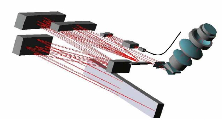
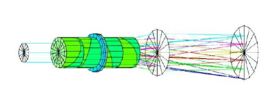
An example of an extremely high stability instrument proposed for an ELT is CODEX. CODEX is a cluster of 5 high-resolution cross-dispersed echelle fiber-fed spectrographs for OWL, working in the visible spectral range. The instrument operates in seeing-limited mode. It covers the spectral band between 450 to 680nm at a spectral resolution in excess of 150,000 (Pasquini et al. 2005). Its main characteristics are summarized in Table 1. Identical spectrographs are mounted inside a vacuum vessel, hosted in a temperature controlled room for maximum stability. Several new concepts have been adopted to ensure high resolution within a reasonable size of each spectrograph: white-pupil, pupil anamorphysm, pupil slicing, VPHG cross-disperser. Each spectrograph is equipped with a R4 1x4 mosaic echelle grating, only twice the size of those of UVES, but with a 8k8k detector. Figure 1 shows the optical layout of one spectrograph unit.
| Characteristics | Required value |
|---|---|
| Sky Aperture | 1 arcsec for 60m telescope |
| Location | nested thermally stabilized environment |
| DQE | 14% including injection losses |
| Number of unit spectr. | 5 |
| Unit spectr. dimension | diam. 2.4 x 4 m (vacuum vessel) |
| Spectral resolution | 150 000 |
| Wavelength coverage | 446–671 in 35 orders |
| Spectrograph layout | white pupil |
| Echelle | 41.6 gr/mm, R4, 170x20 cm, 4x1 mosaic |
| Cross disperser | VPHG 1500 gr/mm, off-Littrow |
| Camera | Dioptric F/2.3, image quality 30 m |
| Detector | CCD mosaic 8Kx8K, 15 m pixels |
| Noise performance | photon shot noise limited at V=16.5 in 10 min |
| Sampling | 4 pixels per FWHM |
We adopted these design constraints:
-
•
No beam larger than 0.5m (need of pupil slicing),
-
•
no two dimensional mosaic of grating (need of anamorphic beam),
-
•
no lenses bigger than 350mm (need of VPH grating).
The instrument will include the following subsystems:
-
•
an image slicer,
-
•
an anamorphic collimator (ratio 1/4),
-
•
a pupil slicer (2 slices),
-
•
an echelle spectrograph operating at magnification 1,
-
•
a reimaging system including a VPH cross disperser.
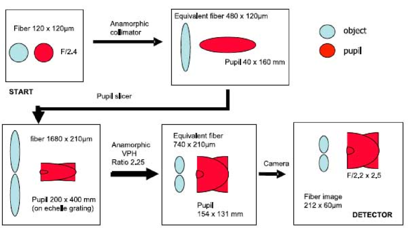
The functional diagram of the optical layout is shown in Fig. 2. A 120m diameter fiber carries light from the telescope focus to the spectrograph entrance slit. Short focal ratios reduce fiber losses due to focal ratio degradation. An anamorphic collimator with a ratio 1/4 creates an elliptical pupil, 40x160mm in size, onto two tilted off-axis parabolas acting as pupil slicer. The equivalent fiber image is elongated at the inverse ratio 4:1, i.e. is seen as a 480x120m fiber. The pupil slicer mirrors overlap the two halves of the pupil, reducing its equivalent size to 40x80mm, and create two adjacent fiber images at the F/4.2 entrance slit of the spectrograph aligned along the height of the slit. This equivalent slit image is 1680x210m. The spectrograph collimator is a three mirrors anastigmat operating in double pass with an anamorphic pupil of 400x200mm, where the echelle grating is placed. This R4 echelle has an overall size of 200x1600mm, i.e., twice that of the UVES grating. After dispersion, light is focused again near the entrance slit of the spectrograph, where a pupil relay mirror sends light toward a transfer collimator of the Maksutov type that creates a smaller light beam. To reduce the size of the slit images a volume phase holographic grating (VPHG) acts in a 2.25 anamorphic magnification, giving an equivalent slit image of 740x210m. At the same time the pupil is compressed at the inverse ratio, giving a 154x131mm pupil. Then the F/2.2 (on-axis) camera reimages the slit image onto the detector with a final projected size of about 212x60m.
The technique of pupil slicing allows the reduction of the grating area by a factor two (2001600 instead of 2003200 mm) for the same resolving power. The price to pay for is factor two for the detector area. To recover such a spread, a VPHG cross-disperser is used to enlarge the beam (x2.25) in the cross-dispersion plane, reducing the detector area by the same factor.
Overall efficiency peaks at 38% with a 28% average, from the fiber exit to the detector focal plane. This estimate is based on the following assumptions:
-
•
99.5% efficiency air/glass interface (20x)
-
•
98.5% per reflection (10x)
-
•
75% average for VPH
-
•
65% average for echelle.
2.2.2 Key system components for CODEX
CODEX will benefit from further development of existing technologies and the exploitation of new ideas. Here we focus on those components that are crucial for a successful development of CODEX.
Light pipe/scrambler: The illumination of the entrance slit must be as stable as possible, in order to reduce calibration errors due to image motions within the slit aperture. This technique has been successful used in HARPS reaching a very high precision in radial velocity measurements 1 m/s (Avila et al. 2004).
Due to ELT image plane scale, such a scrambler should have a 1x0.12mm cross-section, made in fused Silica. In order to pack efficiently many fibers together, a light pipe matched to the exit aperture of some (5-8) fibers is foreseen.
Echelle grating: The R4 echelle grating for CODEX will consist of a 4x1 mosaic of replicas onto the same substrate, with an overall dimension of 170x22cm. In principle it is a “straighforward” extension from the 2x1 mosaic of UVES. However some aspects need to be further investigated, such as its dimensional stability (earthquakes, wavefront).
Beam expander/VPHG: A key component will be the cross-disperser, which is also used as a beam expander. We employ a VPH grating used off-Littrow acting both as crossdisperser and beam expander. With a useful area of 150x150 mm and a groove density of 1500 gr/mm, such elements do not seem too challenging. Efficiency and super-blazing properties need to be studied in detail.
Calibration system: Metrology labs were recently revolutionized by the introduction of femtosecond-pulsed, self-referenced lasers driven by atomic clock standards (Hall & Hänsch 2005). Result is a reproducible, stable “comb” of evenly spaced lines who s frequencies are known a priori to better than 1 in 1015. Advantages are: (a) its absolute calibration, giving a long term frequency stability required by CODEX; (b) evenly spaced and highly precise frequencies allowing a mapping of distortions, drifts and intra-pixel sensitivity variations of CCD; (c) a naturally fibre feed system.
Some properties need to be developed:
-
•
Line-spacing currently limited to 1GHz by laser size and energy considerations. We need 10–15GHz. New technology needed. Development project underway with Max-Planck-Institute of Quantum Optics.
-
•
Transmission of non-linear optical fibre questionable as low as 400nm. Existing technology can probably be extended.
-
•
Moving from the lab to observatory-type environment: industrial quality comb.
Detector Array: A 8k8k CCD area will be needed to correctly sample the echellogram. This corresponds to a 120120mm2 area for a 15m pixel size. Each slit image will be 60m1 mm wide. Three solutions can be envisaged: a mosaic of four 4k4k chips, a mosaic of eight 4k2k chips, or go to a new generation of very large, wafer-sized monolithic CCDs, e.g. currently developed for the Potsdam Echelle Polarimetric and Spectroscopic Instrument (PEPSI) at the 28.4m Large Binocular Telescope (LBT). Challenges are posed by flatness requirements, dimensional and thermal stability (1 mK) and low read noise if light pipe is not feasible.
2.3 Large lenses and their production
ELTs will need large optical components to be used in transmission like lenses, prisms and filters for imaging optics, atmospheric dispersion correctors and wavelength range filtering. The extreme dimensions of these components pose challenges for the production, specification and inspection of the glass blanks.
Between the last mirror in a telescope - may it be a secondary, tertiary or higher - and the detector, transmitting optics is needed with large optical elements for beam shaping, atmospheric dispersion correctors and wave band filters. Even though large transmitting lenses and prisms have been produced in the past (Johnson 2002) this cannot be taken for granted. The optical elements will be even larger and the specifications will be much more stringent reflecting the ambitious scientific goals of the new telescope generations (Hartmann et al. 1996; Hartmann et al. 2002; Doehring et al. 2003; Jedamzik et al. 2004; Doehring et al. 2005). In order to provide optical elements with the required sizes and qualities in time for the completion of the telescopes close cooperation between astronomers and industry will be necessary about the specific requirements and their verification. The developments needed for manufacture and metrology methods have to be addressed. Typical for large optics are long times for manufacturing and for metrology development. Therefore agreements between the designers for the transmitting optics and the manufacturers have to be settled early enough to take the long cycles into account.
The largest piece of optical glass ever made is a 2.15m diameter 350mm thick ZK7 block with a weight of 3.2 tons. It was manufactured 1951 by Jenaer Glaswerke in Jena, Germany by casting the contents of three clay pots together into one mould. It is still in use, as the mirror substrate of the 2 m telescope of the Karl Schwarzschild Observatory in Tautenburg, Thuringia (Hartmann et al. 2004). The main goal of this cast was the size. Since it was meant as a mirror blank, optical homogeneity and striae content were not the first concern. For large transmitting elements in future telescopes these properties will be crucial. They have to be optimized in production and measured to highest possible accuracy. Schott has manufactured blanks with dimensions larger than 1 m and more than 200 mm thickness with outstanding quality since the 1970s. The striae content was very low which could be demonstrated by means of the very sensitive shadowgraph method. The optical homogeneity was proven by the so called statistical method. Small samples were cut from the periphery and compared interferometrically (Reitmayer et al. 1972). The overall refractive index variations were found to be below 4 10-6 peak to valley and even better. The best results have been obtained during an optimized serial production run over several weeks of only one glass type, BK7. Such favorable conditions occur with projects that need a large amount of high homogeneity glass. This will be probably not the case for astronomy telescope aimed production.
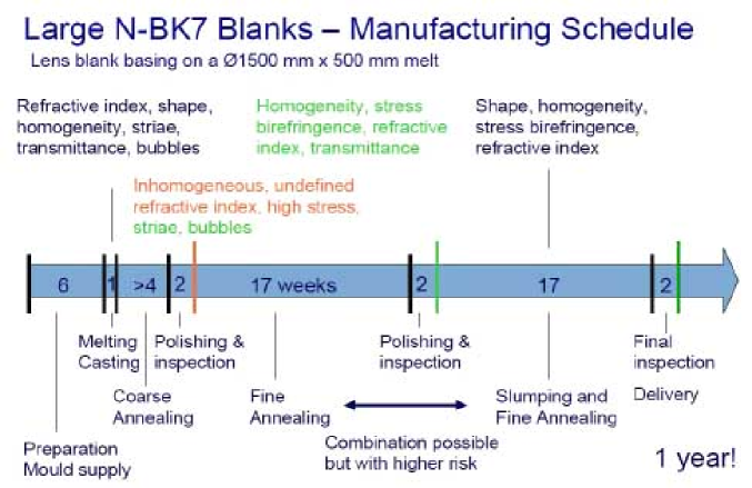
Recently Schott has made an internal assessment of feasible sizes and maximum volumes. With the large continuous melting tank providing the best possibility to achieve high optical homogeneity the maximum dimensions will be 1.5m diameter and 500mm thickness corresponding to 2.2 tons of N-BK7, the present day arsenic free version of BK7. Larger diameters with some preforming of curvatures may be achieved with the slumping method. The glass will be reheated until it gets soft enough to flow under its own weight. Standing in a mould with a larger diameter and a curved bottom, it acquires the new desired shape when sufficient total volume is available. The total production cycle for a slumped large blank easily extends to one year. The cooling down in a certain glass type dependent temperature range, so-called fine annealing, influences the glass quality decisively, see Fig. 3.
This production process is the same for all glass types which are suited for large blank production. This set is restricted mainly to the classical families: boro-silicate crowns and lead-silicate flints with some glasses lying close to them in the fluor-crown and the barium-silicate crown ranges.
This size restriction for optical glass blanks has several reasons: continuous glass production process is not capable to provide arbitrarily high glass flows; and glass flow rate must be limited further to ensure a continuous isotropic flow into the mould to prevent striae. This leads to long casting times from several hours up to almost one day. During this time all technical and environmental parameters have to be kept as stable as possible. The first stability requirement seems to be self-evident, but it is the one excluding most glass types from being candidates for large optics: the glass must remain as a glass. The compositions of many glasses with exotic optical properties have high tendencies to crystallize thus preventing production of an integral solid large piece. The temperature field around the mould must be stable to prevent shape deformations. The refractive index has to be kept very stable, since variations in time will be found as spatial variations i.e. inhomogeneity within the blank. This requires starting with the production of the glass at least two days earlier to keep away from the stronger variations typical at the beginning of a melting run. Temperature controlled coarse annealing preserves the blanks from breakage due to internal stresses. After a first inspection for striae and bubbles and inclusions the glass blank will be fine annealed. This process determines the final refractive index, the optical homogeneity and the stress birefringence. The refractive index of a piece of glass is given by its chemical composition only in the range of 10-3. The final values down to the 6th or 7th decimal place will be fixed by the temperature history this glass piece has undergone in the temperature range from the so-called transformation temperature to about 150 to 200∘C downwards. At the transformation temperature, a glass-type specific value, stress in the glass relaxes within a short time.
During cooling down through this temperature range one must keep the temperature differences in a large piece of glass as small as possible. Otherwise this would lead to different refractive indices at different locations, thus inhomogeneity. Unfortunately glass in general is a poor temperature conductor, so temperature changes easily lead to high differences within the volume. In order to keep the differences at minimum, temperature changes with time have to be kept very slow. Again unfortunately the differences induced in a volume of a poor thermal conductor are not linear with its dimensions. They are proportional to the square of the thickness of a plate. So even if larger blanks could be cast, the annealing times necessary to achieve high homogeneity would become extremely long, too long to be practical.
2.4 Glass properties and their measurement
The main properties essential for the function of a piece of optical glass are: The refractive index, the Abbe number as a measure of dispersion, the optical homogeneity, the spectral internal transmittance, bubbles and inclusions, striae and stress birefringence (Bach et al. 1995; Schott Technical informations, www.schott.com). All are specified in the catalogue and data sheets for all glass types. However the nominal values and tolerances cannot just be used or extrapolated to very large pieces of these glass types. The specially adjusted production processes and process times have influences, which may interact with each other, changing the specification and which have to be taken into account therefore.
2.4.1 Refractive index and dispersion
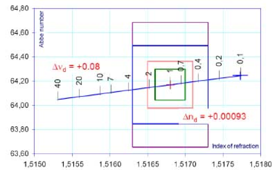
Very long fine annealing will lead to an increase of the refractive index (see Fig. 4 and table 2). For N-BK7 the glass composition for block glass is adjusted for 1∘C per hour fine annealing. Annealing this glass with 0.1∘C/h as necessary for large blanks will increase the refractive index by 0.00093 and the Abbe number by 0.08, thus lying out of the tolerance range. The index d denotes the spectral d-line at 587.6nm. Schott could change the composition to compensate this effect, but glass produced in this ways cannot be used for other purposes. So the customer will have to pay for all preproduction and other “waste” glass. If the instrument optics designer accepts the increased values, the “waste” glass, which is not adequate for the large blank but excellent for smaller pieces may be used for other applications. Measurement of absolute refractive index and the dispersion is well understood. The values are determined by taking samples. A precision test certificate provides the constants of the total dispersion curve from the near UV to the near IR with an accuracy better than 10-5.
| Glass type | ||||
|---|---|---|---|---|
| LLF1 | 1.54814 | 45.75 | 0.00040 | 0.02 |
| LLF6 | 1.53172 | 48.76 | 0.00045 | 0.03 |
| F2 | 1.62004 | 36.37 | 0.00043 | 0.04 |
| SF6 | 1.80518 | 25.43 | 0.00058 | 0.05 |
| N-BK7 | 1.51680 | 64.17 | 0.00093 | 0.08 |
2.4.2 Optical homogeneity
The striae inspection of the glass blank after coarse annealing gives a first assessment of the homogeneity achievable. If there are only very few and faint striae, there is a high chance that the homogeneity will be excellent after fine annealing. But this is only a necessary precondition, not a guarantee. The success of production will be proven only after lengthy fine annealing, half a year after casting.
The common way to specify homogeneity in a catalogue is to give a limit for the peak-to-valley (p-v) value. This value may be misleading to a certain extent. It comprises contributions to the wave front deviation which are not critical for the function of the optical element. Especially the defocusing term can easily be corrected in the optical system. Also astigmatism may be compensated by the rotation of other astigmatic elements in the system to a certain extent. This may allow relaxation of the homogeneity specification, because the terms mentioned normally contribute a significant amount to the p-v value. Adapted polishing may compensate other long-range deviations, additionally. So a close communication between the glass manufacturer and the polisher will be very helpful.
The measurement of the optical homogeneity is the most challenging inspection to be made. The Fizeau interferometers presently used for this purpose have a maximum aperture of 500 to 600mm. For elements up to an effective diameter of 1.5 m there will be no chance to measure them with a single large aperture. In order to build such an interferometer lenses of 1.5 m would be needed – a bootstrapping problem. Other influences like the variations in the environmental conditions like the temperature field around the blank to be measured and around the total interferometer with its large optical elements, vibrations and air flow in the interferometer cavity also limit the maximum possible aperture.
The wave front deviation for plane waves traveling through an optical transparent material with thickness and temperature inhomogeneity is calculated according to Reitmayer & Schroeder (1974) with Eq. 2,
| (2) |
where is the coefficient of thermal expansion, is the refractive index, and is the thermo-optical coefficient of the glass type. The extreme temperature sensitivity of thick pieces of optical materials can be seen by the values calculated with Eq. 2 and given in Table 3.
| Material | |||||
| (-30/70∘) | (20/40∘) | ||||
| 10-6 | 10-6 | 10-6 | |||
| (K-1) | (K-1) | (K-1) | (nm) | ||
| LLF1 | 8.10 | 2.90 | 1.55099 | 7.36 | 147 |
| LLF6 | 7.50 | 3.70 | 1.53431 | 7.71 | 154 |
| F2 | 8.20 | 4.40 | 1.62408 | 9.52 | 190 |
| SF6 | 8.10 | 11.10 | 1.81265 | 17.68 | 354 |
| N-BK7 | 7.10 | 3.00 | 1.51872 | 6.68 | 134 |
| Vitr. Silica | 0.51 | 10.10 | 1.46008 | 10.33 | 207 |
| Zerodur | 0.02 | 14.80 | 1.54470 | 14.81 | 296 |
| Air | - | -0.92 | - | -0.92 | -18 |
| constant of thermal expansion | |||||
| constant of thermal expansion | |||||
| thermo-optical coefficient | |||||
| W | wavefront deformation | ||||
This holds not only for the quality inspection of large blanks but also for their application as optical elements in the telescope. Temperature changes transformed by transmitting materials into wave front deformations will be a significant source for errors.
So there will be no way around stitching sub-apertures. This has been done already (Schönefeld et al. 2005) but only for much smaller sizes. Especially for the specification and verification of the homogeneity it is urgent for the telescope optics designers and the glass manufacturers and the polishers to agree on the values needed. If new larger interferometers and evaluation methods have to be developed, one must take into account long development times (several years) and high costs.
2.4.3 Internal transmittance
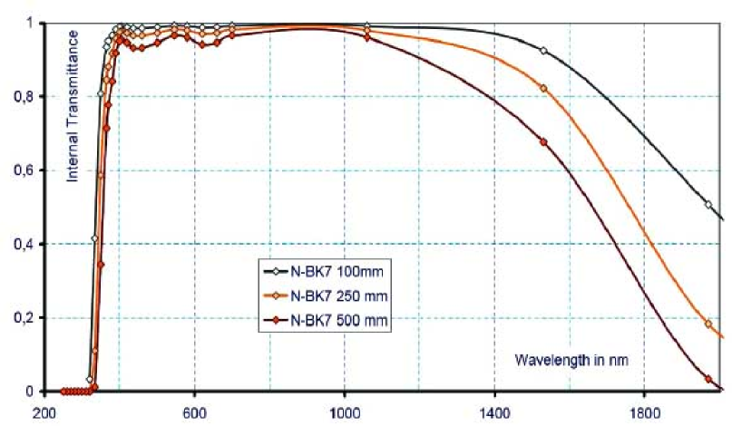
The internal transmittance in the visible range is normally no big concern even for large thicknesses (see Fig. 5). However travelling into the IR wavelength range the internal transmittance starts to decrease. Large thicknesses will pronounce this effect. Measurement using samples is common practice and is representative for a large blank.
2.4.4 Bubbles and inclusions
Candidate glass types for large lenses have typically a very low content of bubbles and inclusions. But the existence of some scattered bubbles cannot be excluded totally. Usually one specifies the ratio of the sum of the effective areas of all inclusions to the area of the optical element. This ratio is a measure of the stray light produced in the element.
2.4.5 Striae
Striae are variations of the refractive index in short-ranges with typical periods between 0.1mm and 1mm. Their main effect is again stray light. One possibility to specify striae is to limit the ratio of the total area covered by striae to the total optical element area disregarding the wave front distortion p-v value. This was applied in the case where some few striae with sharply defined areas existed, when optical glass was made mainly in clay pots. Nowadays the appearance of striae has changed. They may cover larger parts of the total element volume and thus area, but are much smaller with respect to the wave front distortion. Since their wave front distortion effect is proportional to the light path to a certain extent, for common optical glass standard striae quality has been defined to be better than 30nm optical path difference per 50mm path length. The candidate glass types for large lenses have the potential of much better quality as is shown by practical experience. To keep the striae content on a low level will be really a challenge with large glass blanks. Especially close to the edges striae can appear. Since part of the optical elements edge zone will be hidden by mounting assemblies, there may be some room for relaxation of the striae tolerance in this outer zone.
2.4.6 Stress birefringence
Stress birefringence is the other reason for the very long annealing times. The temperature differences in the blank’s volume produced during the ramp down in the range below the transformation temperature will result in permanent bulk stresses. Only lowest annealing rates and smallest possible thickness help in getting best stress birefringence results. The standard tolerance for small optical elements will probably not be sufficient. 10 nm/cm birefringence in block or strip glass is harmless since most elements made out of such glass have only optical path lengths of some cm and additionally stress collapses significantly while cutting blocks to smaller pieces. For large optical glass blanks birefringence will become significant. There is no cutting to reduce bulk stress and the large optical path lengths sum up birefringence to significant amounts. An element with a thickness of 300mm and 10 nm/cm specific birefringence would end up with 300-nm birefringence in total. The optical design would have to take into account wave front retardations of 300nm between orthogonal polarized light rays at maximum varying locally over the elements area. For a well-annealed piece of glass bulk stress is highest at the edge, where it is compressive. It decreases towards the centre, crosses zero and reaches a local maximum at the centre, where it becomes tensile. The effective birefringence results from the interaction of the light with its different polarization directions and the bulk stress tensor field, which makes things very complicated. So the best will be to reduce stress birefringence in total to the best possible value, this is limited by practically possible annealing times.
2.5 Large filters and their production
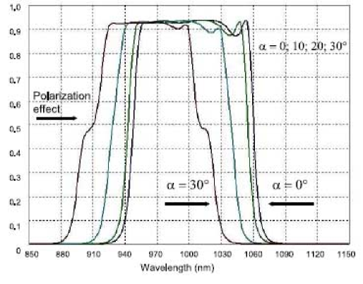
In principle there are two ways to produce large filters, by interference coatings on white or colored substrate glass sheets or by using colored glasses. Facilities for the production of large coated filters have already been developed (Geyl 2004). These filters can be tailored for a very well defined spectral transmittance with sharp edges between the transmitting and blocking ranges. However this holds only for light with normal incidence. With increasing angles of incidence the transmitting ranges shift towards shorter wavelengths significantly, approximately proportional to . Colored glass filters do not have edges as steep as is possible with coated filters especially at the long wavelength cut-off, but they are much less sensitive to the incidence angle.
Instrument designers need sets of different glasses (11 types for the Sloan filter set), which are restricted in size in different ways. Some glass types are produced as large sheets. Others with higher crystallization tendencies would need development to achieve larger dimensions. Since these developments will not just be simple extrapolations, their results are at present undetermined. Furthermore there would be a very bad ratio between the efforts and the possible revenues, so that a commercial company would not do without considerable financial inducement.
Presently available or possible sizes are shown in Table 4. All colored glass types are produced only once in a while since with one production run one obtains the need for one year or even more. The large 900x900mm2 sheets of the GG, OG and RG types are produced only once a year. If there is no special requirement, they will be cut down to small pieces. The vast majority is sold as 50x50mm2 plates. Hence there are time windows where special requirements can be taken into account.
| Filter | Type of | Current sizes | Max. sizes | Notes |
|---|---|---|---|---|
| glass | coloring | produced | current capab. | Larger sizes |
| (mm x mm) | (mm x mm) | |||
| UG1 | ionic. | 220x220 | 240x240 | R&D |
| BG12 | ionic. | 220x220 | 240x240 | discontinued |
| BG18 | ionic. | 240x240 | 360x240 | R&D |
| BG39 | ionic. | 240x240 | 360x240 | R&D |
| KG3 | ionic. | 625x185 | 800x280 | R&D |
| RG9 | ionic./coll. | 360x360 | 900x900 | available |
| GG385 | coll. | 360x360 | 900x900 | available |
| GG495 | coll. | 360x360 | 900x900 | available |
| OG570 | coll. | 360x360 | 900x900 | available |
| RG850 | coll. | 360x360 | 900x900 | available |
| N-WG280 | base glass | 200x200 | 280x280 | R&D |
Because in the past there were no requirements for glass filters beyond 300mm in diameter only little is known about the internal quality of pieces of these sizes. Optical homogeneity and refractive index homogeneity probably will not be a significant problem because of the small thickness of the filters. The optical transmittance homogeneity is not known. First tests will be made soon for the GG, OG and RG types presently being produced. Stress birefringence also will be no problem due to the small thickness. But there may be problems with bubbles and striae. Zones with reduced quality cannot be cut out and thrown away as in the production of small filters. From the production point of view mosaics from hexagonal filter elements would be much easier, much cheaper and much better to be controlled for their quality. It will be worthwhile to recheck the necessity of large monolithic filters in any case.
2.6 Free-form optics
The segments for extremely large telescopes present unprecedented challenges in industrial-scale manufacturing, surface-specification, and metrology. Quality-assurance over a long production-cycle is also an issue. The adoption of a segmented spherical primary mirror goes some way to alleviate the problems, but at the expense of a complex optical system and impaired stray-light and infrared-emissivity both of which are detrimental to key science-goals such as detection of extra-solar terrestrial planets. Simple two-mirror telescope designs are clearly superior, but at the expense of off-axis aspheric segments.
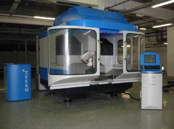
Emerging new technologies can be brought to bear on this challenge. The United Kingdom is investing in a new “National Facility in Ultra-precision Surfaces” which is including a 1m pilot segment production plant for aspheric process-development. Moreover, an automated polishing of free-form surfaces has been set up, which could have a major impact on the optical design of ELT instrumentation.
ELTs will benefit from the ability to produce 1m-size segments, both for the telescope mirrors (primary, secondary, tertiary) and related instrumentation. Such large optical machines put stringent requirements on:
-
•
Delivered point spread function (PSF),
-
•
surface power spectral density (PSD), and
-
•
edge control (segments).
A large project started under the UK Research Council’s Basic Technology Initiative, called “Ultra–Precision Surfaces” and led by University College London and Cranfield University. Its first objective is to establish a national facility where capabilities for complex111i.e., non-rotationally symmetrical and completely free-form surfaces surfaces will be developed, with a substantial improvement in ratio of cost/surface-accuracy.
The technical approach will be optimally to combine several novel processes and manage in a deterministic way residual surface structures to optimize performances. Within these new technologies we have: computer numerical control (CNC) membrane local-polishing, CNC fluid-jet polishing, CNC “grolishing” (a hybrid grinding-polishing process), ultra-precision grinding (Fig. 8), reactive atomic plasma technology, and surface metrology.
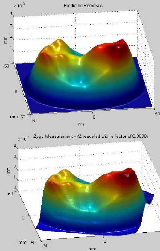
One of the most interesting technologies is the free-form polishing. Predicted and measured results are in agreement as shown in Fig. 9. This technique has a potential impact on instrument design. A complex optical system can be simplified and/or enhanced by giving the designer additional mathematical degrees of freedom. Moreover, fewer optical surfaces with superior image quality, less stray light, and lower infrared emissivity will improve optical performances (e.g., off-axis mirror systems). Finally, it can be used to correct system aberrations on a surface near a pupil image.
3 Metrology for optics
This science of precision measuring of physical parameters is the most important part of the ELT project. High precision and efficient metrology is required in the manufacturing of thousands of large off-axis segmented mirrors. The testing is the bottleneck of the process today not the polishing. Manufacturing large convex secondary mirrors (5m diameter) is difficult and designers are proposing Gregorian telescope increasing the size of the telescope structure because they think that the metrology and testing cannot achieve the accuracy required. We need to invest in brainpower and budget to find ways to overcome these difficulties. In instrumentation there is a huge challenge because the metrology systems (interferometry, profilometry) would be an integrated part of the instrument, have to operate in close loop, be in cryogenic environments, and requiring m or even nm levels of accuracy.
3.1 Testing aspherical surfaces
The importance and the utility of testing aspheres goes beyond the important task of quality assurance and optical component certification. Indeed the popular statement “you can make what you can measure” is particularly true in asphere manufacturing. During the fabrication process frequent surface measurements are needed to determine what is wrong and what can be done to make the surface better especially when it is not possible to maintain under strict control all the parameters affecting the fabrication process.
There are two different measurement methods to test aspherical surfaces: profilometry and interferometry. Even if large profilometers exist, interferometers are often preferred, allowing us to measure the whole 3D shape of a surface. However interferometry with aspheres poses many “new” problems: only part of the beam coming back from the surface will enter the interferometer and will be measured; fringes will be densely packed within the interferogram, asking for very high spatial resolution of the instrument. If fringes cannot be resolved, it is safer to look for optical configurations to “null” the fringes, inserting some optical components or change the test set up in order to finally resolve fringes.
There are no general recipes to find null lens configurations. Simulations can be helpful to understand if the testing configuration is working properly. In some configurations, test rays are not normal to the surface, then the interferogram will not be directly related to surface errors, but will have to be decoded before to be given to the optical workshop for further polishing. Off-axis conical surfaces can be even more difficult to characterize in term of its radius of curvature and conic constant: a good relative error for the latter will often be larger than few thousandths.
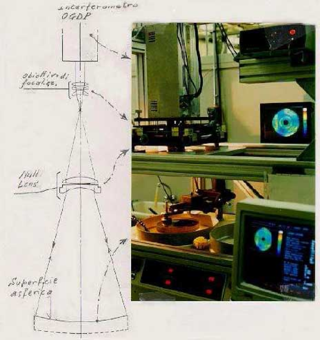
A well known class of conventional null lens are those generated by the “Offner” configuration that can be a good starting point. Refractive null lenses are easier to build by the optical workshop due the availability of tools. A typical application is the continuous measurement of surface profile during final polishing (Fig. 10). Convex surfaces are more and more difficult to measure. Unless for conical surfaces (hyperboloid, ellipsoid), polynomial convex surfaces will require “near” null lens tests, but particular care must be applied to reduce residual errors coming from higher order aberrations.
An issue is how to “test” the null lens: sometimes, when you are testing several identical aspheres, a constant error in the interference fringe pattern can probably be attributed to the null lens itself. When only one surface must be done, computer generated holograms (CGH)can help in simulating the wavefront from the asphere. This technique enables obtaining a surface accuracy (peak-to-valley) of the order of /10, but positioning errors of the CGH must be taken into account.
There are also some tricks, like sub-Nyquist interferometry. This requires less than two pixels per fringe, assuming that first and second surface derivative is continuous. It requires a custom CCD or a pinhole mask, with strong alignment problems. Other solutions are:
-
•
Infrared interferometry for testing pre-shaped (rough) surfaces,
-
•
two wavelength holography (633-nm and 543-nm lasers), and
-
•
high density arrays.
However, a “universal” method to test aspheres does not exist and the engineer should evaluate case-by-case the most appropriate approach as there are several possible setups for testing aspherical surfaces and wavefronts.
4 New materials and innovative processes
Traditional astronomical instrumentation has been mostly designed and built in the last 50 years using metal and glass. Detailed Finite Element Models (FEM), light-weighting techniques, clever optical designs and active controls, allowed scaling up instruments from the 2-m class telescopes to the 10-m class telescope without major modifications in the materials used.
A further scale-up to ELT pupil sizes for seeing-limited instruments is not straightforward first of all because it would turn instruments into very heavy systems difficult to control and to move around with the telescope. Furthermore the requirement on optical component will be moving from “perfect single piece” to “acceptable series production” this because many of the instruments currently sketched for ELTs are made of a number of identical subsystems.
Materials such as Polymeric compounds, composites, light metals, functional alloys a.o. will likely be progressively introduced into astronomical instrumentation design. Accordingly innovative processes such as ion beam figuring, holography, etc. will as well progressively replace traditional manufacturing techniques.
This section, reporting the discussion of this session of the workshop, intends to assess the status of the art in the above fields and serve as a baseline for future joint institute-industry developments.
4.1 Production of large-size volume phase holographic gratings
Efficient dispersing elements are of great interest in astronomical instrumentation; moreover the possibility of making large size gratings fits the needs of new instrumentations for current large telescopes and the next generation ELTs. Volume phase holographic gratings (VPHGs) are good candidate for these aims (Barden et al. 1998, Barden et al. 2000, Blanche et al. 2004).
VPHGs are dispersive elements as are conventional surface relief gratings but, instead of having dips and bumps, the diffraction is achieved by refractive index modulation of the bulk material (Smith 1977; Schankoff 1968; Chang 1979; Hariharan 1984). So, light coming from the instrument passes through the grating and the dispersed spectrum is behind the grating.
Due to their intrinsic structure, volume phase gratings possess unique properties (Kogelnik 1969; Barden et al. 1998):
-
•
They have a theoretical efficiency of 100%.
-
•
The undiffracted part of the spectrum is not perturbed by the grating and can be reused for other applications. In this configuration, the grating acts like a filter.
-
•
Glued between two prisms, the diffracted spectrum is not deviated which allows to have a straight pass spectrometer: the Littrow configuration. These prisms/grating elements are named “grisms”.
-
•
The superblaze property: Changing the incidence angle of the light arriving on the VPHG shifts the blaze wavelength. Envelope of all the blaze curves for different angle is called “superblaze”. This property broaden the useful bandwidth.
-
•
Gratings are recorded by holographic setup. This allows to record large size in one single laser shot instead to rule each line one by one. Thus, each grating is a master.
-
•
Sturdiness: the active layer (few microns of dichromated gelatine) is encapsulated between two blanks. VPHG elements can so be handled and cleaned as regular piece of glass.
These advantages make VPHGs the best choice as spectrometer dispersive element and this is why they are more and more used by astronomers when it comes to design new instruments (Arns et al. 1999; Monnet et al. 2002; Blanche et al. 2002; Andersen et al. 2004).
For tens of years, the Centre Spatial de Liège had the know-how to produce this particular type of grating. In year 2000, a new facility was set up which allows both research and manufacturing of large VPHGs (Habraken et al. 2001, 2002; Blanche et al. 2002). In 2005, in order to distribute these elements, the ATHOL company was founded (acronym for “Advanced Techniques in HOLography” for Optics).
Manufacturing VPHGs at ATHOL requires three steps:
-
•
Coating the active layer,
-
•
recording the grating with holographic setup, and
-
•
processing the film to develop the index modulation.
Of course, it is also required to check and certify all the parameters of the gratings after production, such as line density, efficiency, blaze wavelength, bandwidth, and wavefront errors.
4.1.1 Monolithic gratings
ATHOL coats own dichromated gelatine from 2m up to 25m. Thickness is certified by grooved spectra measurement. The blank size the whole system can accommodate is about 500 mm a side. The clear aperture of the recording setup is 380 mm of diameter. The capabilities are VPHGs with fringe frequency from 300 lines/mm up to more than 3500 lines/mm. These limits can be overcome for gratings of smaller size but the horizontal dimension can also be enlarged when the beam is made oval during the casting on to the recording plane.
The largest monolithic VPHG made so far at ATHOL was a 380-mm diameter grating for the Osservatorio Astronomico di Brera in Italy. Figure 11 shows this grating diffracting a beam from a halogen light. The first order spectrum is diffracted on the right and the colored circle is the zero order which contains the complementary colors since nearly 100% of the light at the blaze wavelength is diffracted.
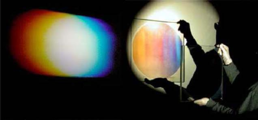
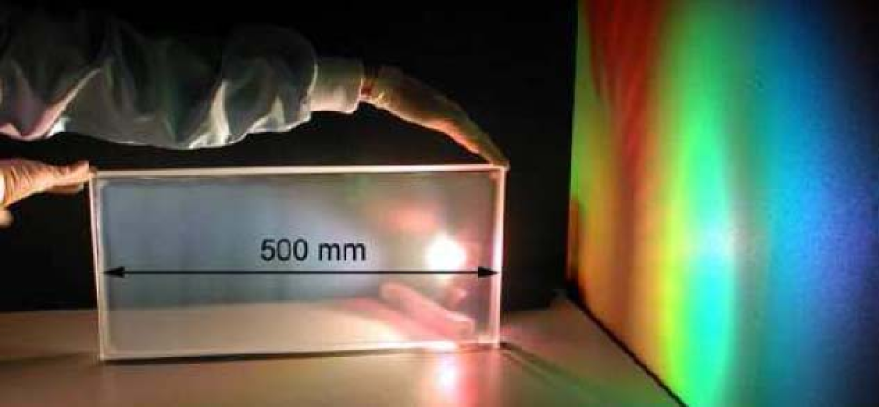
Figure 12 presents a monolithic grating produced for NOAO where ATHOL took advantage of the enlargement of the recording beam horizontal axis. Indeed, with a recording angle of , beams are made to be oval on the substrate and so enhance the size to 500 mm.
But whatever the size of the facility, it will always be finite and this restrains the instrument designer’s creativity. To overcome this problem first tests with the the mosaic technique were performed.
4.1.2 Mosaics
The mosaic technique consists of assembling several gratings recorded and processed independently. Challenges are that mosaic subelements have to diffract at exactly the same angle and according to the same blaze and superblaze. That means that gelatine thickness and index modulation have to be perfectly matched from element to element.
Moreover, during the encapsulation, elements have also to be co-aligned precisely in order to avoid any tilt between recorded fringes. Such an angle will induce diffraction by the elements in different directions.
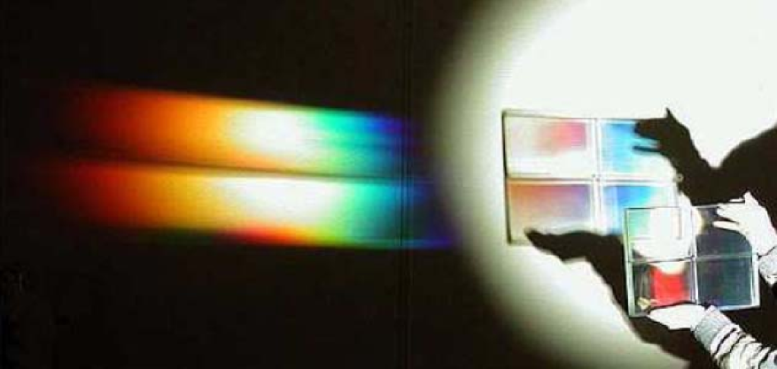
Two mosaics were produced for NOAO, both consisted of four elements for a total size of 340x240 mm. Figure 13 shows one of these mosaics. Note that spectra perfectly overlap, proving the good alignment of the subgratings. The dark middle line appearing in the spectrum is due to beam baffling by the blanks beveled edges. Thanks to the mosaic technique, the size of the setup no longer matters and the final grating diameter becomes virtually unlimited.
4.1.3 Cryogenic operation
VPHGs can be manufactured so that they diffract in the infrared. Up to now, ATHOL made gratings diffracting up to 2.5 microns. However, in spite of their infrared effectiveness, their actual use is restricted to spectrometers running at ambient temperature. This is due to lack of knowledge of their behavior in cooled IR spectrometers which have to operate at cryogenic temperature.
To use VPHGs as IR dispersive elements, one has to ensure they will survive. Experiments were made at ATHOL that placed samples in a cryogenic vacuum vessel and measured efficiency as well as diffracted wavefront at ambient temperature as well as down to liquid nitrogen temperatures.
Efficiency: Rather to measure the diffraction efficiency of the +1 order, the 0 order transmission efficiency is measured. Using a fiber spectrometer allows to record the blaze curve in one single measurement and to avoid a light collection problem into the fiber.
Ensuring there is no higher order, +1 and 0 order efficiency are related by the following relation
| (3) |
where the losses take into account Fresnel reflection, absorption, and diffusion. Thus, such measurements record an efficiency dip instead of being an efficiency bump.
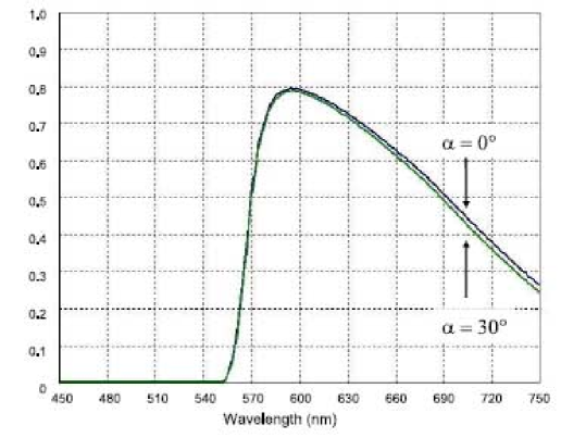
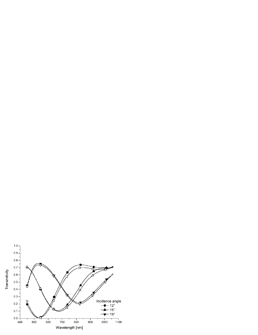
Figure 14 shows 0 order transmission efficiency of a VPHG for various incidence angles at ambient temperature and cooled down to C. At both temperatures, the blaze is still at 550 nm and the observed fluctuations are less than 5%. This value is of the order of the shift due to grating-stand thermal contraction and errors due to the goniometric-arms repositioning. No significant decrease of the efficiency has been seen.
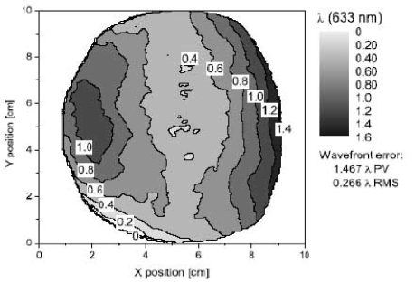
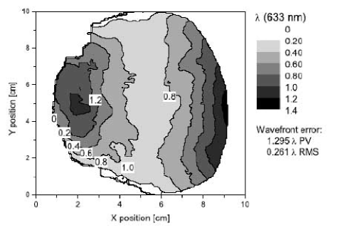
Wavefront: We measured the wavefront diffracted by one of our VPHG at ambient temperature, during cool-down and at stable cryogenic temperature. We notice that the higher the thermal gradient on the grating, the larger is the wavefront error. But, when thermal stability is ensured by few degrees, the wavefront relaxes near to its original shape. This is what is depicted in Fig. 15, where the diffracted wavefront errors measured by a Zygo interferometer at ambient temperature and at 150 K are plotted. In both graphs, amplitude and shape of the wavefront is similar.
It must be noted that all tested grating survived the thermal cycles imposed on them. There were no degradation of the gelatine clarity nor cosmetic damages.
4.1.4 Post-polishing
Depending on the blank thickness and characteristics, gelatine processing and cement shrinkage can induce some stress. This stress can lead to wavefront deformation. A solution is to correct the wavefront by post-polishing after the grating has been encapsulated. Because VPHGs are so sturdy this is feasible. However, the diffracted wavefront can be a complex function without any symmetry. In this case, classic polishing is rather tricky. ATHOL used the ion beam figuring method (see Sect. 4.4) where an ion gun throws particles to the grating substrate and removes material where needed.
Figure 16 presents the diffracted wavefront of a VPHG before and after post-polishing. The RMS wavefront error has been reduced from to by ion beam figuring over a diameter of 100 mm.
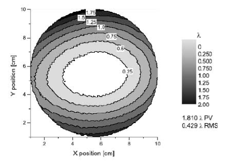

By using ion beam figuring it is also possible to induce any kind of wavefront; converging, diverging, asymmetric, and so on. Of course, optical functions can also be directly implemented into the hologram during the recording. Then, one can truly speak of a “holographic optical element”.
4.2 Organic photochromic materials
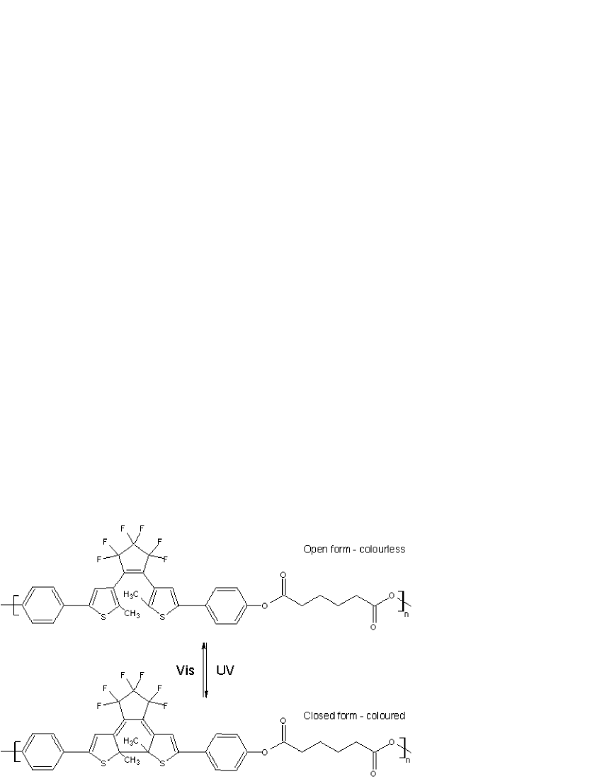
Photochromic materials change their absorption spectrum, and consequently their color, by means of an optical stimulus. This change is reversible by using light of different wavelength or it is simply induced by the temperature. This kind of materials finds applications in many technological fields, for example as sun filters, optical switches, optical memories (Crano & Guglielmetti 1999a, 1999b). The two stable forms of photochromic materials differ not only for color but also for refractive index, IR spectrum, redox potential and other physical-chemical properties. Among the classes of photochromic materials, we focused our attention and efforts to the class of diarylethenes, since they have good properties in terms of high fatigue resistance, thermal stability, and photochromic efficiency, which are important for practical application (Irie 2000).
Usually the materials are used in solid state and in particular as films of different thickness; therefore, it becomes important to have materials with good filmable properties. By using low molecular weight molecules, a polymer matrix (such as polymethylmetacrilate) is usually needed and this limits the content of active molecules to few percent (10%) in order to keep the film homogeneity. Another approach is the synthesis of backbone photochromic polymers, which combine the processability of the polymer materials and the optical properties of photochromic materials (Stellacci et al. 1999, Kim et al. 2002, Bertarelli et al. 2004, Wigglesworth et al. 2004). We used the photochromic polymers to make rewritable elements for astronomical instrumentation.
4.2.1 Focal plane masks
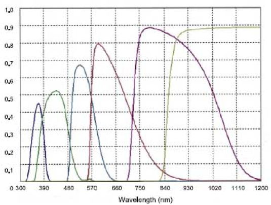
We exploited the change in transparency of a photochromic film in the visible to make rewritable focal plane MOS masks (Multi Object Slits; Molinari et al. 2002, Bianco et al. 2005): the film is turned into the opaque form, then a red laser writes the slits turning the photochromic film into the transparent form. OAB built up a complete set-up to read the pre-imaging and, after defining the slits position, to write automatically the slit pattern. The spectral range is limited (500–700 nm) by the photochromic material and the filters used. The performances can be improved by choosing proper filters that match exactly the passband of the photochromic film. Figure 17(top) shows a plot of the transmission curves of a photochromic mask (70m thick) in the opaque form and the curves of two filters designed to match the film passband. In this configuration, the whole system is opaque over the entire range of sensitivity of the Si CCD.
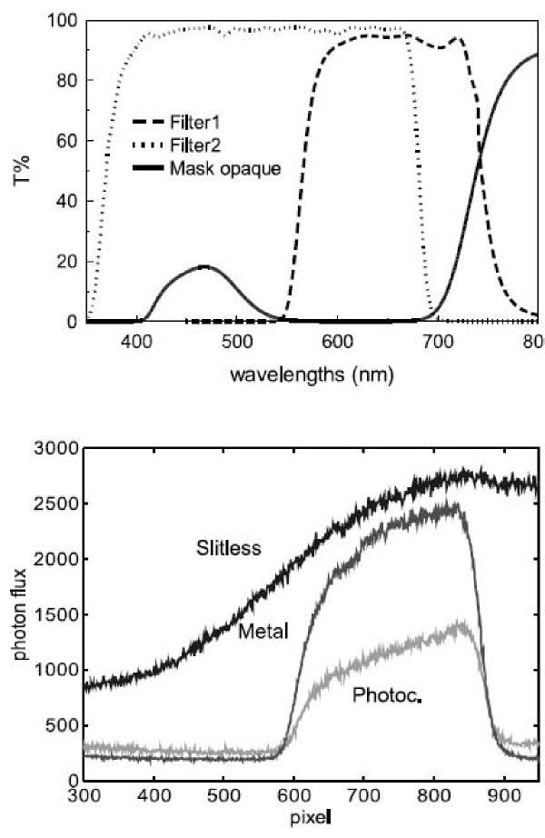
The most important parameter related to the transmission curves of the mask is the contrast between the slits and the mask. Since the photochromic film is not completely opaque, there is a background noise that is not present in the metallic mask, especially in the spectroscopic mode. The results are shown in Fig. 17(bottom), obtained with the AFOSC camera (Asiago telescope, Italy) by using a flat field as light source and a single slit. The metallic mask clearly shows an higher signal through the slit compared to the photochromic mask. The ratio between the signals is about two and consequently the noise of the metallic mask is smaller.
4.2.2 Volume phase holographic gratings
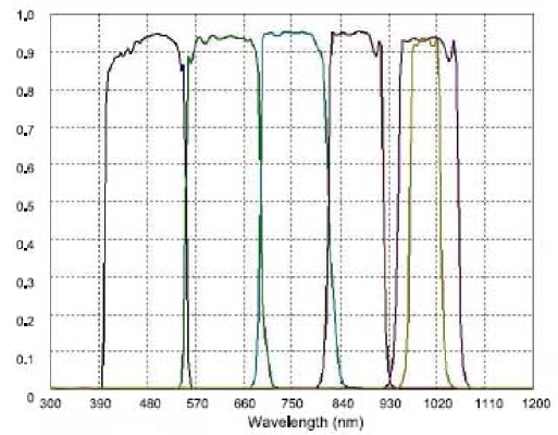
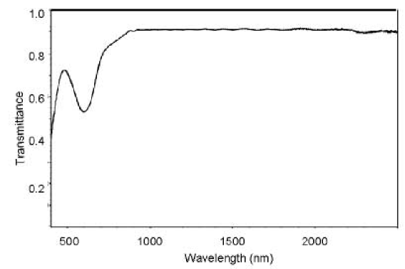
Efficient dispersing elements are of great interest in astronomical instrumentation; moreover, the possibility of making large size gratings fits the needs of new instrumentations for current large telescopes, and the next generation ELTs. Volume phase holographic gratings (VPHGs) are good candidate for these aims (Barden et al. 1998, Barden et al. 2000, Blanche et al. 2004). This kind of dispersing element exploits the periodical difference in refractive index that takes place in particular materials, therefore the diffraction happens in the volume of the material. Usually, VPHGs are made of a thin layer of dichromated gelatine (DCG), which is cast on a glass substrate, exposed to laser light pattern (488 nm) and then developed by a chemical treatment (Curran & Shankoff 1970; see also Sect. 4.1). The efficiency curve of these gratings depends on the thickness of the layer and on the modulation of the refractive index (). Because of the developing process, the thickness of DCG layer is limited to 20 30 microns. By using a material that changes the refractive index without any chemical process remove this limit and it makes easier the VPHG manufacturing. Photochromic materials show a between the two forms and this difference is easily achieved by using light of suitable wavelength (Bertarelli et al. 2004), since the change in refractive index is due to a different electronic structure of the molecules instead of a different density as in the case of DCG. The useful spectral range for VPHGs made of photochromic materials (Molinari et al. 2002) is the near infrared where the material is completely transparent (see Fig. 18); the transmittance is close to 90% between 800 nm and 2500 nm, which means, taking into account the reflection losses (more than 8%), a negligible absorption or scattering. These VPHGs will be useful for astronomical instrumentations working in the J, K, L bands.
Reaching large n for films of photochromic materials (0.01–0.08) is the fundamental requirement in order to make VPHGs with large peak efficiency and without a shrinkage of the blaze curve (increasing the thickness). Table 5 clearly shows that the n obtained with low molecular weight photochromic diarylethenes is small, since they need a polymer matrix, whereas the diarylethenes polymers have a large modulation. Among the different classes of photochromic polymers, polyester P1 (chemical structure in Fig. 19) was synthesized since they have good efficiency in both the photochromic reactions; moreover, the molecular weight is large enough to make make good optical films by casting.
| Photochromic materials | (1.5 m) |
|---|---|
| Low molecular weight molecules (a) | 0.001–0.005 |
| Backbone photochromic polymers (b) | 0.003–0.032 |
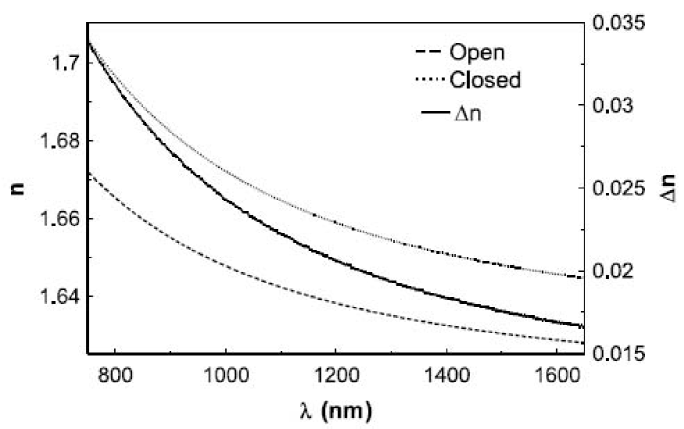
The refractive index of the two forms of the photochromic polyesters was measured by using spectral reflectance between 800 and 1600 nm. A thin film (300 nm) was spin coated on a glass substrate and the reflectance is measured. A fit based on a Cauchy model () was applied and both the thickness and the refractive index were determined. The maerial in its coloured form has a refractive index larger than the colourless form. The n increases when the wavelength decreases. This is a difference from the DCG, which shows a constant modulation, and it affects the efficiency curve of the VPHG. At 1500 nm the of P1 is 0.0165, large enough for an efficient VPHG (see Fig. 19).
The sensitivity of P1 was also measured by using green laser (514 nm) starting from a film in the coloured form. The laser power and the area of the spot were measured, then the polyester film was lightened with the laser and the laser power was monitored until a plateau was reached as function of time. At the wavelength used the sensitivity is 120 J/mm3. This parameter is important to determine the exposure time of the film to the light pattern. Films of pure P1 for VPHGs were obtained by using a control coater with a spreading blade, that casts the polymer solution at constant thickness. The target thickness was 20m, but homogeneous films of only 5 microns were cast successfully. Low viscosity of the solution was most probably the cause of the too thin films. Some attempts to increase viscosity were made by adding a small amount of PMMA with an high molecular weight (120,000 or 1,000,000 g/mol), but in this case, the films turned out to be opaque. Consequently the efficiency of a VPHG could be very low. Starting from a film 4.5m thick, a VPHG was written by transferring the pattern of a Ronchi ruling glass slide (600 l/mm, OD=3) with a green laser (532nm, 30mW).
In order to check the result of the writing procedure, images of the recorded film were obtained by optical microscopy. Figure 20(a,b) shows the similarity of the pattern of the Ronchi glass slide and the photochromic film.
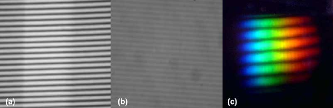
At this level it was not possible to quantify the contrast profile of the pattern, which could give the conversion grade of the photochromic layer, but we were able to obtain a diffraction pattern from a white lamp and our photochromic grating (see Fig. 20c). At present, the main issue remains the possibility to make thick films based on photochromic polymers.
Usually the dispersing elements must show high efficiency over a wide spectral range; for VPHGs it means a large refractive index modulation and thin films. Increasing the thickness and lowering the n, the passband of the VPHG shrinks and the peak efficiency remains close to 1. In this configuration the grating behaves as a filter with a narrow passband that can be tuned in wavelength by changing the incidence angle (Molinari et al. 2004, Havermeyer et al. 2004). This kind of tunable filters could be robust and cheap. Simulations based on Rigorous Coupled Wave Analysis (RCWA, Gaylord & Moharam 1982) were carried out on a thick photochromic film (800 microns,n = 0.001) to verify this possibility and the results are summarized in Fig. 21.
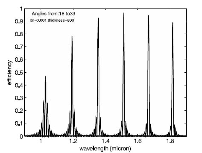
A thick film of optical polymers such as polymethylmethacrylate (PMMA) doped with photochromic molecules can be a good substrate, since, as mentioned previously, the photochromic materials do not need a chemical process. A simple device which exploits the features of such VPHGs is composed of two counter-rotating Rayleigh prisms which modulate the incidence angle on the grating leaving the optical axis of the system unperturbed (see Fig. 22).
4.3 Sintered SiC mirrors for ELTs
The recurring concept for ELT’s outstandingly large mirrors (primary and also secondary) is using a hexagonal segmentation, with a flat to flat size between 1m and 3m. The main drivers for the choice of the mirror segment material are:
-
•
Specific stiffness and thermal stability and
-
•
manufacturing capability at cost effective condition and with reasonable time span.
4.3.1 SiC material characteristics
The Boostec material is a sintered silicon carbide (SSiC) which has been fully characterized, even down to cryogenic temperatures. In comparison with the glass-ceramics and the other types of silicon carbide materials, it offers a very interesting package of properties. These SiC materials are:
-
•
SiSiC, reaction bonded or Si infiltrated,
-
•
C/SiC or CeSiC, including short carbon fibres, also Si infiltrated, and
-
•
CVD (Chemical Vapour Deposited) SiC.
The telescope materials are selected for
-
•
their high specific stiffness (Young s modulus / density) which enables manufacture of lightweight parts with high mechanical stability;
-
•
their high thermal stability (thermal conductivity / coefficient of thermal expansion), which give a lack of sensitivity to temperature changes.
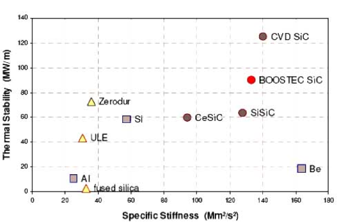
Thanks to its high stiffness (420 GPa) and its high thermal conductivity (180 W/mK at RT) the Boostec SiC appears among the best choices in Fig. 23. The only CVD SiC shows better properties, thanks to both a very high purity and a total lack of porosity. Unfortunately, all attempts for manufacturing large monolithic mirror blanks with this CVD material failed. On the other hand, its physical properties fit very well with the ones of the sintered SiC; this is the reason why it is currently suggested by Boostec as a cladding on its material, when a small surface porosity cannot be tolerated. The Figures of Merit of Boostec SiC are enhanced when the temperature is decreased from room temperature to 100 K.
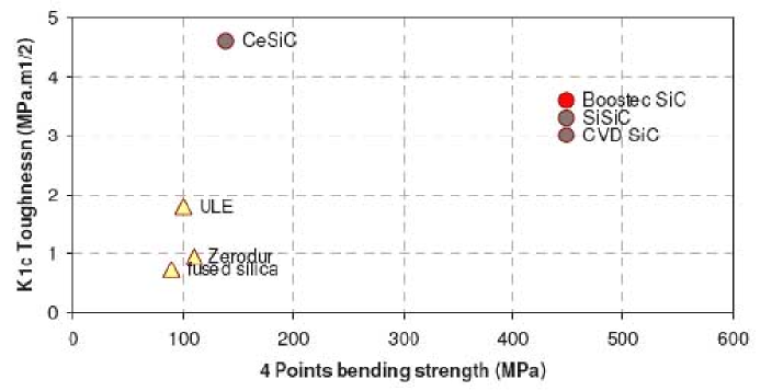
All SiC materials exhibit significantly higher strength and toughness than fused silica and also than glass-ceramics (Fig. 24). An addition of short carbon fibres slightly improves the K1c toughness which can be assumed as the resistance to the crack propagation. But this is clearly obtained to the detriment of the mechanical strength of these C/SiC materials. Boostec s sintered SiC, as well as infiltrated (fine microstructure only) and CVD ones show the best mechanical strength. Both CVD and Boostec SiC exhibit homogeneous and isotropic microstructure. They have no secondary phase, no outgassing, no sensitivity to moisture and an outstanding resistance to strong acids or alkalis.
Boostec SiC is furthermore insensitive to mechanical fatigue. It shows around 1.5 vol.% closed porosity, which is commonly masked with a CVD SiC cladding when necessary. Even if they are harder than the glass-ceramics, Boostec SiC or its possible SiC CVD cladding can be easily polished with standard mechanical diamond polishing and Ion Beam Figuring. Their single phase, their fully isotropic properties, their lack of plasticity and their high stiffness are very helpful. They do not require any relaxation time thanks to both their low mass and high thermal conductivity. All the standard optical coatings of glass-ceramics can be also applied on these SiC materials.
4.3.2 SiC manufacturing capabilities and large size abilities
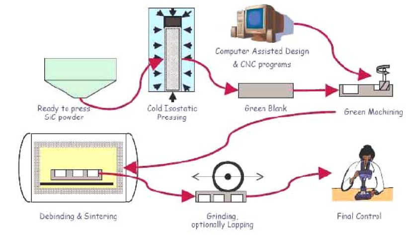
Boostec SiC manufacturing process for monolithic parts: Monolithic SiC parts of up to 1.5x1.0m can be manufactured according to a process which is summarized in Fig. 25. Boostec uses a near-net-shaping technique, i.e. that the shape of the part is obtained mainly by machining the “green blank”, before sintering. Soft blanks machining makes Boostec process very productive and cost effective. All curved profiles, possibly aspheric or off-axis, are obtained from CNC grinding machines, after sintering.
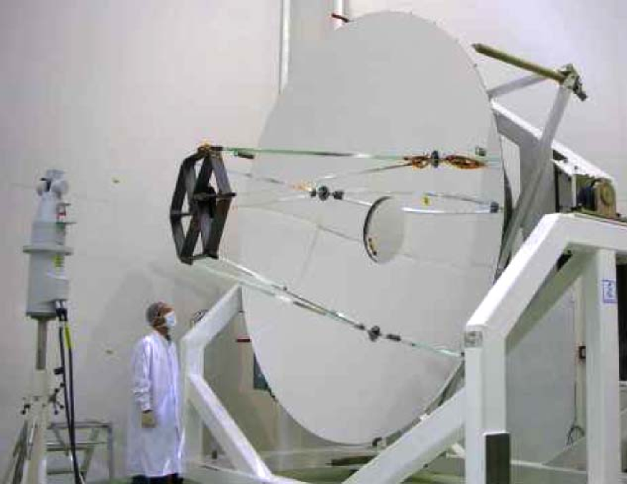
Manufacturing very large SiC parts: Sintered SiC parts can be joined together thus obtaining parts larger than 1.5x1.0m. To this extend, Boostec has developed and qualified a non reactive brazing process. A braze alloy is used since its CTE fits very well with that of SiC. This process has been successfully used on several space projects such as the 1.5-m diameter parabola of the Aladin telescope and the 3.5-m diameter Herschel primary mirror. No technological limitation has been revealed so that sizes limits of both monolithic and brazed blanks could most likely be increased.
Assembling SiC parts: Two assembling techniques have been developed, qualified and also successfully used in space telescopes: (a) bolting SiC-SiC or SiC-metal with metallic bolts, (b) gluing SiC-SiC or SiC-metal with epoxy material.
4.3.3 Production experience
Mass production of sintered SiC: The world production of synthetic SiC is 900,000 tons per year from which a very small part is used as raw material for the production of around 450 tons of sintered SiC. The ability to manufacture very cost effective components has already been demonstrated for highly competitive areas like automotive or armours. Before developing SiC optics, Boostec team has accumulated more than 10 years experience in mass production of seal or bearing rings made of sintered SiC. The telescope material is the same as the one manufactured for such industrial applications.
Production of sintered SiC telescopes: Since the end of the 1990’s, Boostec has developed space telescopes fully made of SiC (mirrors, structure, focal plane), in close collaboration with EADS Astrium. This experience can be summarized in 4 main steps:
-
•
1998-1999, Osiris Narrow Angle Camera which has been embarked on the ESA ROSETTA satellite, now traveling towards the Churyumov-Gerasimenko comet (Castel et al. 1999).
-
•
2000-2001, Rocsat 2 telescope, a Cassegrain type remote sensing instrument now in operation for Taiwan (Uguen et al. 2004).
-
•
2001-2004, ESA Herschel telescope to be launched in 2008 (Fig. 26, Toulemont et al. 2004). Its 3.50-m parabola is undoubtedly the most challenging space mirror part that has ever been manufactured in the World.
-
•
2003-2004: Aladin instrument (Morancais et al. 2004). This 1.5m Lidar will be embarked on the Aeolus ESA mission in 2008.
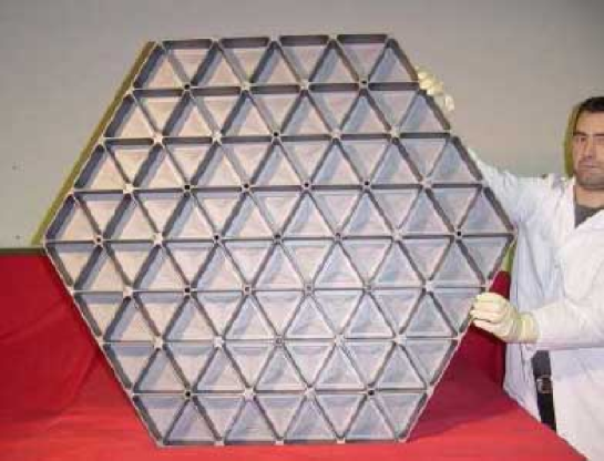
OWL-type segments have been designed with EADS Astrium assistance (a) 1.00 meter flat to flat, (b) flat optical surface ready for polishing or deposition of a polishable coating, (c) face sheet thickness 5.5mm, (d) ribs thickness 4.0mm, (e) overall thickness 80mm (f) 19 possible points of interface. Their weight per unit area is only 44 kg/m2. Four segments demonstrators have been successfully manufactured and delivered to ESO in 2003 (Fig. 27).
4.3.4 Feasibility mirror segments for ESO’s OWL
The huge primary and secondary mirrors of OWL would be made of thousands of hexagonal segments, the size of which should be between 1.3m and 2.3m. In 2001, Boostec carried out feasibility and cost studies for the fabrication of such segments with its SiC technology. It demonstrated the easy feasibility of 20 to 30 segments per week. Such a fabrication would not bring any disruption in the world production of sintered silicon carbide. The full set of OWL segments blanks appeared also feasible within a competitive price range.
A preliminary design analysis performed by ESO team (Dierickx et al. 2004) has shown that the savings on the total moving mass could be around 5,000 tons (from 14,800 tons) when using SiC M1 segments instead of glass-ceramics ones. Mass saving has positive impacts at almost every level of the system design, in terms of performance, safety and costs. Eliminating unnecessary structural masses reduces flexures and stresses, implies less powerful drives, relaxes requirements for the concrete foundations, reduces transient thermal distortions, and simplifies integration (ESO OWL website, www.eso.org/projects/owl/).
4.3.5 Adaptive optics with SiC?
ELTs will require adaptive optics for wave front error correction. The reflective face and the back plate of such deformable mirrors could be also advantageously made of SiC. The optical faces will be large and thin shells, around 2mm thick, possibly segmented and then off-axis. The back plates will be large and stiff structures, including thousands of interfaces with the actuators. Even though no technological obstacle is foreseen, such deformable mirrors in SiC would undoubtedly require development work.
4.4 High accuracy optical finishing through ion-beam figuring
The focal plane instrumentation for the future ELTs will use large optical surfaces made in different materials and probably with aspherical shapes. These optics are generally difficult and expensive to manufacture within the tight tolerances requested for astronomical instruments. A process that has been proven to be effective in the high precision figuring of the optical surfaces is the Ion Beam Figuring (IBF). This technique was originally developed by Eastman Kodak Company in 1988 and is an excellent complement to conventional figuring.
The optics are first polished conventionally and then the final figure is milled by the IBF. The optics are inserted into a high-vacuum chamber facing down. The IBF then directs a beam of ions upward to the glass that is hence removed on a molecular level. The beam itself is translated across the optical surface removing the errors leftover from the conventional polishing, leaving behind a very smooth surface. The ion beam is produced by a Kaufman type ion source using Argon gas. The shape of the beam (removal function) is “Gaussian like” and its erosion rate (etching) is very constant in time for a given setup of the parameters controlling the ion head, i.e. the electrical voltages, the Argon flow, the distance ion head mirror. The material is removed from the optic by transfer of kinetic energy from the argon ions to the atoms of the optical surface. The dwell time map and the movements of the ion source necessary to remove the thickness of material are computed comparing the actual surface with the target surface figure. The correct thickness of material is then etched by rastering with the appropriate velocities the ion beam in front of the optical surface.
This technique has the advantage that is deterministic (time saving), is a non-contact method (good for lightweight optics) and has high removal rates (50-100 nm/min). The main disadvantages are that it needs the vacuum (complex technique), the substrate can heat during the figuring and if the quantity of material removed is large (more than few microns) the surface micro-roughness can increase depending from the material. This technique is of crucial importance for figuring SiC optics because, due to the material hardness, it is very difficult to reach a good figuring accuracy with classical methods. Of course, other materials such as BK7, Zerodur and Quartz can be easily figured as well.
An IBF facility has been recently developed at the INAF-Osservatorio Astronomico di Brera (OABr) for the high precision machining of optical surfaces. The facility (Fig. 28) consists of a stainless steel vacuum chamber (1.4m height and 0.8m diameter), suitable for figuring optics up to 500mm diameter. A two stage mechanical pump is used for initial pump-down while the high vacuum is obtained with a cryo-pump able also to take care of the small volume of Argon gas used in the sputtering process. A “Kaufman” ion source is mounted on two carriages (x-y) with stepper motors. A “bridge” is used to suspend the optic above the source that can be moved in x-y to reach the point of the surface to be figured.
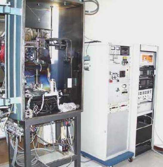
The system is computer controlled and has been designed to be autonomous and self-monitoring during figuring by using a proprietary process control software. This software uses a time matrix map indicating the dwell times required for each pixel of the optical surface. This time matrix and the tool path necessary to correct the errors are computed considering the actual surface error map, the ion-beam removal function and the final target surface. The software and the mathematical tools used to compute the time matrix solution has been developed at INAF-OABr.
An example of the performance that can be obtained with IBF are the two 150-mm SiC demonstration mirrors for NIRSpec for the JWST. For both mirrors it has been possible to obtain a precision of /70 rms at 632.8 nm, confirming the high accuracy that can be achieved with this technology. Currently, a new IBF facility is under construction at OABr that will be able to figure optics up to 1.5m of diameter. Figure 29 shows the vacuum chamber with a dimension of 2m in diameter and 3m in length.
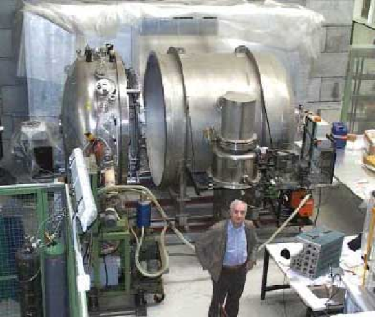
4.5 Fused quartz and silica for large optics
Crystal glasses as fused quartz and silica seem to be most appropriate for large optical components in ELT instrument design, due to their very high grade and reproducible properties.
Dimensions available: Blanks with diameters up to 1m are now available. Above this size, further development are required in cooperation between the few producers in the world. Thickness will vary according to diameter and weight restrictions. Indeed, overall weight should be maintained below 500 kg.
Transmission: In the infrared, transmission is influenced by OH absorption bands, while in the ultraviolet by purity. See Fig. 30. New materials are under development, such as Heraeus Suprasil-3001, with higher performances.
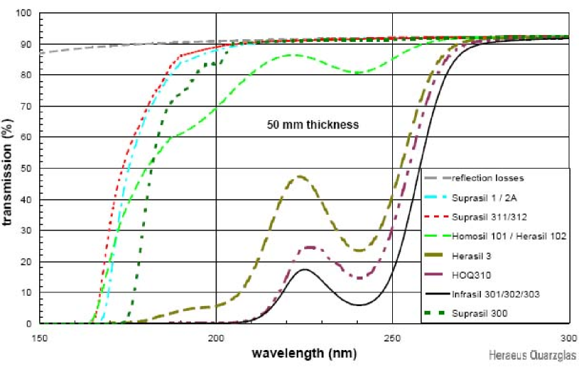

Birefringence: For large pieces (diameter 350-1000mm) it accounts for less than 5 nm/cm, while for smaller pieces (350mm diameter) values below 0.5 nm/cm are possible. These very small numbers open manufacturing of very large optics.
Homogeneity: For large pieces, homogeneity grade as low as n=2 10-6 are possible. Moreover no high spatial frequencies are present. For smaller pieces, homogeneity four times smaller is feasible.
Bubbles and inclusions: Conventional SiO2 glasses are affected by bubbles and solid inclusions at very different levels. Very few glasses can be made with almost no bubbles and/or inclusions. For example, Heraeus Suprasil-312 is produced without any imperfection.
5 Smart Focal Planes
There is a need to ensure that instruments for ELTs make best use of the high information content of the focal plane, both for imaging and spectroscopy. The OPTICON Joint Research Activity on Smart Focal Planes (Cunningham et al. 2005) has developed a range of optical technologies to enable multi-object and integral field spectroscopy, from robotic pick-off devices and reconfigurable slit mechanisms to replicated image slicers.
5.1 Pick-off technologies for multi-object ELT instruments
Many of the scientific goals for future Extremely Large Telescopes, including key fields such as the formation of galaxies at earlier epochs or studies of the stellar population in neighbouring galaxies, call for a multi-object capability from an instrument. It has been proposed (Russell et al. 2004) that such an instrument may be highly modular, comprising a number of identical imagers or spectrographs observing in parallel. The number of sub-instruments would depend on the limitations of the instrument conceptual design, but may be as many as one per instrument. Current examples of modular instruments include KMOS (3 spectrographs for 24 targets, Sharples et al. 2004) and MUSE (24 spectrographs for 24 fields), both being built for ESO’s Very Large Telescopes. We call the opto-mechanical means to pick-off areas of the focal plane means to feed these sub-instruments “Smart Focal Plane” technology.
Pick-off technologies are an exciting field of opto-mechanical development with several approaches of varying technical readiness currently under development. The space densities, field sizes and clustering of the science targets, coupled with instrument design constraints, will drive the choice of multi-object technology. For infrared astronomy on an ELT, the requirement to work at reduced temperatures, often cryogenic, in order to minimize thermal background radiation places significant constraints on the technologies used to place pick-off mirrors and lenses in the focal plane. Hydraulic mechanisms, for example, are obviously precluded. The three techniques presented here; pick-off arms, Starbugs and a “Planetary Positioner” system have potential for use in a variety of cryogenic instruments and highlight the issues and trade-offs which will be required when developing Smart Focal Plane optics for ELTs.
The UK Astronomy Technology Centre (UKATC) has designed the pick-off technology for KMOS, a K-band multi-integral field unit spectrometer that will use 24 pick-off arms to relay 24 fields to three spectrometers. Pick-off arms are attractive in that it is possible to include a trombone style path length compensator into the arm to ensure that the focal plane is reimaged at a fixed focal plane (in the case of KMOS, onto fixed integral field units). Arms are also attractive in that the position of each pick-off mirror can, with suitable optical calibration, be ascertained by mechanical metrology without the need for an independent optical metrology measurement for each pick-off mirror placement. With 24 arms, it is obviously important that the reliability of each of the mechanisms be extremely high, which presents a challenge to the quality of the cryo-mechanical engineering. For an ELT instrument requiring of the order of 100 pick-offs, the space requirements of an arm would appear to preclude this technique as an option. The KMOS pick-off arms are about to undergo cryogenic tests.
Starbugs is a new concept from AAO that uses piezo actuators to place a miniature optical platform on an arbitrarily large focal plane. The concept is being developed within the OPTICON Smart Focal Planes project (McGrath et al. 2004). Starbugs include a magnet within the platform which enables them to grip effectively to a steel focal surface at any gravity vector. On this platform a variety of payloads such as pickoff mirrors or fibres may be mounted. As each of the bug platforms can move simultaneously, a bug speed as low as 1 mm/s can enable the pick-off observation pattern to be reconfigured in as little as 5 minutes. Tests at temperature down to -100 ∘C have been conducted, with satisfactory, though lower, operational speed recorded. A destination arrival accuracy near 10 m with a loop cycle time of under 100ms has been achieved. Operation in an ELT instrument would require the introduction of an optical metrology system covering the entire focal surface and control software not without some complexity. A further challenge for starbugs is that their present manifestation requires power wires which trail behind each bug, and wireless operation is currently being considered.
A further new technique which is scalable with regards object number is the planetary positioner system; a pick-and-place system which enables magnetic pick-off mirrors to be placed perpendicular to an arbitrarily curved focal surface with the minimum of mechanisms. Presently being built and tested at UKATC, ASTRON and CSEM within the OPTICON Smart Focal Plane programme, the planetary positioner system also has the benefit of an intrinsic measure of the position of the mirrors. However, though the time taken to position each mirror can be relatively short, it will likely be necessary to configure the mirrors ”off-line” and rotate the focal surface into place for the observation run in a similar way to that of “2df” (Colless 1999).
5.2 Complex multi-sensory-motion systems
Most concepts currently being conceived are based on a complex layout comprising a large number of sensory-motion elements, numbering in the hundreds, and eventually in the thousands, of active components. This approach, beside its advantages in terms of massive scientific capability, exponentially increasing with respect to currently available instruments, offers as well a perspective for escaping the a parallel exponential increase of cost by exploiting more industrial technologies and production methods.
There are some technological developments which are recognized to be potentially of use in next generation instrument concepts.
Mechanical slit masks: for multi-object spectrographs. This mechanism creates a mask by placing two sets of bars. Multiple objects can be selected in the available field-of-view, by translating separate rectangular bars towards each other and creating a rectangular opening (slit) on the focal plane of the instrument. Each bar has its own sensory-motion system, which result in a quite complex multifold actuator mechanism.
Starbugs: The starbug concept has been proposed since some time (McGrath et al. 2004) as a next generation smart focal plane system for astronomical instruments. From a technical standpoint, it consists of a materialization of the focal plane as an opaque surface, on which are placed and, in some version, may travel small “starbugs” that are optical pick-up elements which can have various functions. Eventually, a starbug instrument would number thousands of small opto-mechatronic systems. The current starbug prototypes made by AAO are not autonomous, which limits greatly their demonstration aspects. However, there exist a number of projects for “real” micro-robot of comparable size. These autonomous micro-robots are sensory-motors units with generally two independent axes, hence functionally comparable to the what is expected from a starbug, whether motor axes are used for mobility or/and to move optical devices located on the robot.
MEMS (micro electro-mechanical systems): have long be envisaged as a key technology for astronomy, but this has not yet materialized, beside the current slit mask development for JWST. The figure shows a MEMS microlocomotion device developed at CSEM. The MEMS has hexagonal shape with a footprint of about 0.5 cm2. It comprises on its downside 150 “legs” which can move it in a millipede manner with a speed of the order of 1 cm/sec.
3D technology: may be proposed for the packaging of electronics. This is based on the stacking of electronic components (chips, plastic packages, sensors) placed on a film. This solution allows mounting the plastic components, ire-bond the chips on the films and testing them, even making a burn-in before stacking (depending on the applications).
Wireless power: Power autonomy is an obvious issue for starbugs. The precise quantification of such requirement will depend on the operative duty-cycle. One option is to take advantage of existing RFID (Radio Frequency Identification) technology components and networking technology to provide wireless power and data transmission from the starbugs floor.
6 The economics of astronomical instrument developments
It is nowadays recognized that astronomy lives presently a golden age. Never before have such blooming of research instruments and associated funds be available for astronomical developments. Nonetheless, in spite of this relative abundance of financing and technical resources, astronomical technology cannot yet pretend to drive by itself the development of new technology. Even if the budget of a new instrument for a large telescope is currently planned in the range of 20 Meuro, such amounts are still one order of magnitude less than a ”small” space science mission, and two orders less than an innovative space telescope such as JWST, not to mention any serious military development. Therefore, because of absolute economical resource limits, new concepts for astronomical instruments remain tributary of existing developments and can only take an essentially opportunistic approach in which technologies developed (and paid) on other contexts are utilized and adapted. Even when such adaptation may and will generally require significant engineering work, it has to be set on firm technological ground and be provided with an already established production base. The increasing size of projected instruments, associated to concepts providing for large numbers of identical or similar components, even reinforces this aspect. If older, simpler instruments could be made at institutes with special custom designs and fabrication, the current concepts with multi-components would result exceedingly expensive if each of these components requires a special design and fabrication. Therefore astronomy developers need to become better aware also of the economics underlying the development and implementation of new technology suitable for their applications.
”Let us reduce costs by taking advantage of industrial components, methods, etc.”: such a sentence is often heard among participants of an early definition phase for new instruments and telescopes. Actually, this approach tends to overlook many realities of industrial production. First, the fact that industrial products are not always cost-effective.
-
•
An automobile is cheap, at least measured in terms of capability per kg.
-
•
But, the ASIMO humanoid robot (made by car manufacturer Honda) is very expensive, even the much simpler AIBO (dog-like) is very expensive (per kg) with respect to a car.
It is then quite evident that an astronomical instrument will by its very specialized nature be more like ASIMO than a series production automobile. Another key aspects to consider are some fundamental differences of the process of development for industrial equipment with respect to an astronomical instrument.
-
•
Instrument: the customer (institute) is also the end user
-
•
Industry: the customer uses the object to produce other equipment or goods
-
•
Instrument: cost (price) is (should be) driven by technical requirements
-
•
Industry: cost (price) is driven by the added value which the costumer will produce with the item.
-
•
Instrument: technical requirements are initially set very severely, then often relaxed, and ultimately astronomers are (almost) always happy with an outcome often quite below initial requirements
-
•
Industry: the technical requirements are strictly derived and adapted to the economic ones. If at some stage the economy fails its promise, the project is dropped
The fact that many future instruments will be based on multiple sensory-motion systems, numbering in the hundreds, perhaps thousands, suggests that economy of scale can play a key role in the costing of such instruments. Yet, economy of scale is a broad concept, not to be simply treated to mean that the cost of making multiple copies of a successfully demonstrated prototype decreases manifold. Establishing an economy of scale for a given component may take many steps and levels. Typically each step ”saving” on the unit production cost requires investment in any of many domains:
-
•
Production facilities.
-
•
Organization and personnel culture.
-
•
Packaging (e.g. wiring).
-
•
Control, inspection (quality, etc.).
-
•
Assembly.
Furthermore, maturity (i.e. number of product generations) is also an essential aspect of a profitable economy of scale.
Clearly, industry usually active in the business of industrial components cannot view and price its product to an institute in the same way it does for an industrial customer. Thus it should be up to the instrument institute to provide industry with different incentives that will contribute to common interests. Instrument developing institutes should take a mutually constructive approach in their relations with industrial partners.
From the production point of view, one still does not see that the optical transmitting elements are treated with the attention necessary to provide the performance needed for the telescopes of the next generation. There is a need for close cooperation between the glass manufacturer, the polishing companies and the optical designers of the telescopes to prevent bad surprises.
7 Summary and conclusions
ELT instrumentation will require significant developments in the area of optical design, material production, optical manufacturing, metrology, assembling, and opto-mechanics. A lot of efforts are underway to increase present capabilities and performances of classical optical components such as mirrors and lenses, mostly in order to obtain larger sizes, better homogeneity, higher surface quality a.s.o.. New materials and technologies are under study to find solutions for the next generation ground telescopes and their instruments.
In this paper, we showed how classical and new-technology optics can be employed and where new developments are needed. Here we summarize current results in different fields of optical engineering.
-
•
Dimensions of the transmissive optical elements must be kept as small as possible. With large lenses this holds especially for their thickness. Thickness determines the thermal inertia of the lens, which is the cause for many problems in production and in operation of optical elements. Due to the quadratic influence of temperature differences in the glass volume, even small thickness reductions will help.
-
•
Internal imperfections will lead to stray light. Or they may become visible if they are close to an intermediate image plane.
-
•
Segmented filters of large size can be constructed today. The edges of the elements of a large mosaic filter may be treated like striae. If this is taken into account in the design of the total optical system, locations may be found where imperfections will not disturb or where they can be tolerated or corrected in the subsequent image processing.
-
•
Reflective large optics should be used often.
-
•
Optical transmitting elements are essential for the function of large telescopes. All of the immense efforts in designing and constructing of ELT mirrors and instruments may be in vain, when the intermediate optics fail.
-
•
Volume phase holographics gratings are a mature technology; not just for regular size spectrometers but also ready for extremely large instruments. A monolithic grating of 380 mm of diameter exists, and size can be further enlarged by using the mosaic technique. These gratings stand cryogenic temperatures and work properly in these conditions considering both efficiency and wavefront errors. Moreover, the diffracted wavefront can be corrected by polishing the blank after the grating has been encapsulated. All these aspects make VPHGs attractive as dispersive element for ELT spectrometers.
-
•
Diarylethene photochromic materials are useful and flexible in astronomical instrumentation. Exploiting their change of transparency in the visible wavelength range, rewritable focal plane masks were built, characterized, and successfully tested. The performances are good in terms of writing slits. The contrast between the slits and the opaque background can be increased by using filters well tailored for the specific photochromic material.
-
•
Photochromic polymers were synthesized to make self-standing films with large modulation of the refractive index. These films could be the base of highly efficient, near-infrared VPHGs working in the J-, K-, and L-band. Present results suggest that photochromic polyesters are promising materials for VPHGs to be used in next generation astronomical spectrographs.
-
•
With an ion beam figuring facility it will be possible to make thin adaptive mirrors, segments for large telescopes, large light-weight optics for space applications and, of course, focal plane optics for large instrumentation. In conclusion, it is clear that ion beam figuring is a technique that will be useful for the manufacturing of complex optical surfaces that will be necessary for ELTs.
-
•
Sintered silicon carbide (SSiC) shows very attractive characteristics for space or ground telescopes. Its specific stiffness could allow saving of moving mass. A lot of technological developments and qualifications were successfully applied to large space telescopes, making this technology ready for large ELTs optics manufacturing.
-
•
Free-form optics enlarge the parameter space available to optical designer to meet instrumental requirements. It even allows to correct for aberrated instruments when such optical elements are inserted along the light path in an existing instrument.
-
•
Metrology plays a fundamental role for ELT instruments, both during the construction phase and the operational phase. Wavefront sensing, adaptive optics, mirror edge sensing and segmented actuators offer additional degree of freedom to relax manufacturing tolerances, both for telescopes and their instruments.
-
•
Aspherical surfaces are always challenging and very need careful preliminary analysis in order to be successfully employed. No recipes exist but test set-ups need to be searched for.
Acknowledgements.
OPTICON has received research funding from the European Community’s Sixth Framework Programme under contract number RII3-CT-001566.References
- [1] Andersen, M.I., Spanò, P., Woche, M., Strassmeier, K.G., Beckert, E.: 2004, SPIE 5492, 381
- [2] Andersen, T., Ardeberg, A.L., Beckers, J. et al.: 2003, SPIE 4840, 214
- [3] Arns, J.A., Colburn, W.S., Barden, S.C.: 1999, SPIE 3779, 313
- [4] Avila, G., Kohler, D., Araya, E. et al.: 2004, SPIE 5492, 669
- [5] Bach, H., Neuroth, N.: 1995, “The properties of optical glass”, Springer & Verlag
- [6] Barden S. C., Arns J. A., Colburn W. S.: 1998, SPIE 3355, 866
- [7] Barden S. C., Arns J. A., Colburn W. S., Willis S. et al.: 2000, PASP 112, 809
- [8] Bertarelli, C., Bianco A., Boffa V., et al.: 2004, Adv. Func. Mat. 14, 1129
- [9] Bertarelli C., Bianco A., D’Amore F. et al.: 2004, Adv. Func. Mat. 14, 357
- [10] Bianco A., Bertarelli C., Gallazzi M.C. et al.: 2005, AN 326, 370
- [11] Blanche P.A., Gailly P., Habraken S. et al.: 2004, Opt. Eng. 43, 2603
- [12] Blanche P.A., Habraken S.L., Lemaire P.C. et al.: 2002, SPIE 4842, 31
- [13] Castel, D., et al.: 1999, SPIE 3785, 56
- [14] Chang, B.J.: 1979, Optical Information Storage 177, 71
- [15] Colless, M.M.: 1999, Phil. Trans. Roy. Soc. Lond. A 357, 105
- [16] Crano, J.C., Guglielmetti, R.J. (eds.): 1999, “Organic Photochromic and Thermochromic compounds, Volume 1, Main Photochromic Families”, Plenum Press, New York
- [17] Crano, J.C., Guglielmetti, R.J. (eds.): 1999, “Organic Photochromic and Thermochromic Compounds, Volume 2, Physicochemical Studies, Biological Applications, and Thermochromism”, Plenum Press, New York
- [18] Cunningham, C.R., Atad, E., Bailey, J., et al.: 2005, SPIE 5904,281
- [19] Curran R. K., Shankoff T.A.: 1970, Appl. Opt. 9, 1651
- [20] Dierickx, P. et al.: 2003, SPIE 4840, 151
- [21] Dierickx, P. et al.: 2004, SPIE 5489, 391
- [22] Doehring, T., Hartmann, P., Morian, H.F., et al.:2003, SPIE 4842, 56
- [23] Doehring, T., Hartmann, P.: 2005, Proc. of “Instrumentation for Extremely Large Telescopes”, Ringberg Castle, in press
- [24] Gaylord T. K., Moharam M.G.: 1982, Appl. Phys. B 28, 1
- [25] Geyl, R.: 2004, SPIE 5494, 393
- [26] Habraken, S., Blanche, P.A., Lemaire, P. et al.: 2001, The Messenger 106, 6
- [27] Habraken, S., Lemaire, P., Blanche, P.A. et al.: 2002, SPIE 4485, 460
- [28] Hall, J.L, Hänsch, T.W.: 2005, Foreword of “Femtosecond Optical Frequency Comb: Principle, Operation, and Applications”, J.Ye and S.T.Cundiff eds., Springer Science and Business Media, 1
- [29] Hariharan, P.: 1984, “Optical Holography. Principles, Techniques and Applications”, Cambridge Univ. Press, 2, 312
- [30] Hartmann, P., Mackh, R., Kohlmann, H.: 1996, SPIE 2775, 108
- [31] Hartmann, P., Morian, H.F., Jedamzik, R.: 2002, SPIE 4411, 6
- [32] Hartmann, P., Morian, H.F.: 2004, SPIE 5382, 285
- [33] Havermeyer F., Liu WH., Moser C.: 2004, Opt. Eng. 43, 2017
- [34] Hawarden, T.G., Dravins, D., Gilmore, G.F. et al: 2003, SPIE 4840, 299
- [35] Irie, M.: 2000, Chem. Rev. 100, 1685
- [36] Jedamzik, R., Hartmann, P.: 2004, SPIE 5494, 382
- [37] Johnson, K.L.: 2002, SPIE 4411, 147
- [38] Kogelnik, H.: 1969, Bell System Technical Journal 48, 2909
- [39] McGrath, A.J., Moore, A.: 2004, SPIE 5492, 353
- [40] Molinari, E., Zerbi, G., Bortoletto, F., et al.: 2002, SPIE 4485, 469
- [41] Molinari, E., Bertarelli, C., Bianco, A., et al.: 2003, SPIE 4842, 335
- [42] Molinari E., Bianco A., Bertarelli C. et al.: 2004 SPIE 5494, 228
- [43] Monnet, G.J., Dekker, H., Rupprecht, G.: 2002, SPIE 4485, 439
- [44] Morancais, D. et al.: 2004, Proc. 5th Intern. Conf. on Space Optics, Toulouse
- [45] Pasquini, L. et al.: 2005, The Messenger 122, 10
- [46] Reitmayer, F., Schuster, E.: 1972, Appl. Opt. 11, 1107
- [47] Reitmayer, F., Schroeder, H.: 1974, Appl. Opt. 14, 716
- [48] Russell, A.P.G., Hawarden, T.G., Atad-Ettedgui, et al.: 2004, SPIE 5382, 684
- [49] Schönefeld, D., Reuter, T., Takke, R. et al.: 2005, SPIE 5965
- [50] Shankoff, T.A.: 1968, Appl. Opt. 7, 2101
- [51] Sharples, et al.: 2004, SPIE 5492, 1179
- [52] Smith, H.M. (ed.): 1977, “Holographic Recording Material”, Springer & Verlag, vol. 20
- [53] Stellacci, F., et al.: 1999, Adv. Mat. 11, 292
- [54] Toulemont, Y., et al.: 2004, Proc. 5th Intern. Conf. on Space Optics, Toulouse
- [55] Uguen, G. et al.: 2004, Proc. 5th Intern. Conf. on Space Optics, Toulouse