Integration of Acoustic Detection Equipment into ANTARES 111 This work was supported by the German BMBF Grant No. 05 CN2WE1/2.
Abstract
The ANTARES group at the University of Erlangen is working towards the integration of a set of acoustic sensors into the ANTARES Neutrino Telescope[1]. With this setup, tests of acoustic particle detection methods and background studies shall be performed. The ANTARES Neutrino Telescope, which is currently being constructed in the Mediterranean Sea, will be equipped with the infrastructure to accommodate a 3-dimensional array of photomultipliers for the detection of Cherenkov light. Within this infrastructure, the required resources for acoustic sensors are available: Bandwidth for the transmission of the acoustic data to the shore, electrical power for the off-shore electronics and physical space to install the acoustic sensors and to route the connecting cables (transmitting signals and power) into the electronics containers. It will be explained how the integration will be performed with minimal modifications of the existing ANTARES design and which setup is foreseen for the acquisition of the acoustic data.
1 Introduction
A promising alternative to neutrino telescopes detecting Cherenkov light in a transparent medium (ice, fresh water, sea water) with optical attenuation lengths of several tens of meters arises from the fact that particle showers with energies exceeding values in the order of 100 PeV produce detectable bipolar pressure waves in water of about s length with a range of up to several km. This effect is described by the thermo-acoustic model and has been experimentally verified for proton and laser beams[2]. Acoustic neutrino telescopes therefore might allow for future giant-volume detectors in the order of 1000 km3.
A necessary prerequisite to develop acoustic detection methods is the detailed understanding of background conditions and the investigation of signal identification methods. In order to acquire the long-term, high-precision data needed for this purpose, it is intended to instrument a part of the ANTARES detector with acoustic sensors.
2 The ANTARES detector and its data acquisition system
The ANTARES detector is currently under construction in the Mediterranean Sea, off-shore of Toulon, and is connected to the coast by an electro-optical cable of about 40 km length. The instrumented area will range from a depth of about 2000 m to 2400 m. The detector is designed to detect the Cherenkov light from muon tracks. For this purpose, it will be equipped with a total of 900 optical modules[3] (OMs), which hold one photomultiplier tube (PMT) each inside a sphere, pointing downwards at an angle of 45∘.
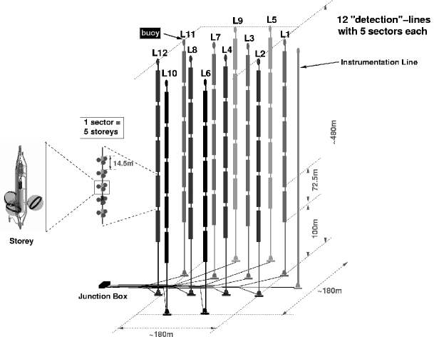
When finished, the detector will consist of 12 “detection lines”, arranged in an octagonal shape on the seabed at a distance of about 70 m from each other (cf. Fig 1). In addition, one “instrumentation line” will hold equipment to record environmental conditions such as the current profile and the salinity of the sea water.
Each detection line comprises 25 storeys at a distance of 14.5 m from each other. Each storey consists of a mechanical support structure that holds 3 OMs and a titanium container with the required electronics (“local control module”, LCM). Five storeys form a sector which constitutes one unit for purposes of data readout. It is foreseen to integrate the acoustic detection equipment into ANTARES in the form of “acoustic sectors” with acoustic sensors replacing the PMTs and using as much of the infrastructure provided by ANTARES with as little changes as possible. This will be described in detail below.
Each LCM contains a backplane that is equipped with connectors for the electronics cards and provides power and data lines to and from the connectors. In each sector, one LCM is designed as Master LCM (MLCM) which in addition to its data taking tasks manages the data transmission to the shore through single-mode optical fibres using TCP/IP. The main electronics cards of a LCM are:
-
•
A clock card, which provides a time stamp to each recorded PMT-value with a resolution of 50 ns and a precision of about 0.5 ns[4];
-
•
So-called ARS-boards which contain 2 Analogue Ring Sampler (ARS) ASICs[5] each, conditioning and digitising the analogue data from the PMTs. Furthermore, they subdivide the 50 ns clock signal into 256 steps. In each LCM, 3 ARS boards are installed to read out the 3 PMTs per storey.
-
•
A data acquisition or DAQ card, which reads out the ARS boards and provides the communication to the MLCM of the sector via TCP/IP.
In the standard sampling mode, an ARS-chip is triggered by a PMT signal above a predefined threshold and then employs a pulse shape discriminator to recognise single photon events—for which the integrated analogue charge is then digitised and read out. The data rate, which is dominated by background from 40K and bioluminescence, therefore can be adjusted by varying the threshold for single photon events.
The bandwidth of the complete data acquisition chain is limited by the throughput of the DAQ-boards which—as will be explained below—limits the number of acoustic sensors that can be installed per storey.
3 Integration of acoustic sensors and their readout
The acoustic sensors that are currently developed and tested by the ANTARES group at Erlangen are described in Ref. \refciteNaumann. The two design concepts (individual hydrophones and “acoustic modules”, in which acoustic sensor elements are installed in the spheres of the optical modules instead of the PMTs) do not differ in their requirements for the electronics inside the LCM.
The fundamental guideline for the design of the acoustic detection system has been that the implementation shall be done with as few modifications to the existing ANTARES design as possible. These considerations have lead to the following layout principles:
-
•
In order not to compromise the suitability for a deep-sea environment, no modifications must be done to the titanium container or the penetrators and connectors leading into and out of the container. Consequentially, only the 3 holes that are present in each container for the cables leading to the 3 OMs can be used to connect to the acoustic sensors.
-
•
In the LCMs of the acoustic storeys, the ARS boards will be replaced by “Acoustic ADC boards”; no other changes to the electronics will be done. These boards will digitise the acoustic data and format them, where the format will be exactly the same as that of the optical data from the ARS boards. The acoustic data will then be read out sequentially by the DAQ board and transmitted to shore in exactly the same fashion as the PMT data.
-
•
On-shore, the separation of acoustic and optical data will be based on their origin, i.e. on the IP address of the DAQ-board in the corresponding LCM. Acoustic data will be separated from the main data stream and processed, filtered and compressed on a dedicated PC-farm.
The number of hydrophones per storey is limited by the data throughput of the DAQ-board processor of roughly 20-25 Mb/s. Consequentially, 6 acoustic sensors per storey can be installed for a 16-bit digitisation and a 200 kHz sampling rate. The sampling rate can be further increased if an adequate down-sampling is performed on the acoustic ADC board.
Each of the 3 acoustic ADC boards per LCM will contain two 16-bit ADCs with a maximum sampling frequency of 500 kHz for the processing of two acoustic sensors. The data sampling will not be triggered but instead be continuous at an adjustable data rate of 100 kHz, 200 kHz or 400 kHz. It will be possible to individually disable each hydrophone.
In order to minimise the development time and error-proneness while maximising the flexibility of the system, no ASICs will be developed. Instead, a FPGA will be employed to process the data from the two ADCs per board and a micro controller to control the FPGA and to allow for the uploading of upgrades of the FPGA code.
The acoustic data will be provided with a time stamp derived from the standard ANTARES clock in order to allow the correlation of the data from several storeys. The electric power consumption of the design will be below W per storey, which is the power available for acoustics per electronics container.
4 Outlook and summary
It is foreseen to install two acoustic sectors with up to 60 acoustic sensors in total into the ANTARES detector. For this goal, a conclusive concept has been devised by the Erlangen group. It is currently under discussion inside the ANTARES collaboration where to place the two acoustic sectors. In the meantime, the development of “acoustic ADC-boards” in Erlangen is progressing.
References
- [1] http://antares.in2p3.fr/
- [2] K. Graf et al., 1st International ARENA Workshop, Zeuthen, Germany (2005) [arXiv:astro-ph/0509450], and references therein.
- [3] P. Amram et al., Nucl. Instrum. Meth. A 484 (2002) 369 [arXiv:astro-ph/0112172].
- [4] F. Blanc et al., proceedings of 28th International Cosmic Ray Conferences (ICRC 2003), Tsukuba, Japan, 31 Jul - 7 Aug 2003.
- [5] F. Druillole et al., IEEE Trans. Nucl. Sci. 49 (2002) 1122.
- [6] C. Naumann et al., 1st International ARENA Workshop, Zeuthen, Germany (2005) [arXiv:astro-ph/0511243].