Lyot Coronagraphy on
Giant Segmented-Mirror Telescopes
Abstract
We present a study of Lyot style (i.e., classical, band-limited, and Gaussian occulter) coronagraphy on extremely large, highly-segmented telescopes. We show that while increased telescope diameter is always an advantage for high dynamic range science (assuming wavefront errors have been corrected sufficiently well), segmentation itself sets a limit on the performance of Lyot coronagraphs. Diffraction from inter-segment gaps sets a floor to the achievable extinction of on-axis starlight with Lyot coronagraphy. We derive an analytical expression for the manner in which coronagraphic suppression of an on-axis source decreases with increasing gap size when the segments are placed in a spatially periodic array over the telescope aperture, regardless of the details of the arrangement. A simple Lyot stop masking out pupil edges produces good extinction of the central peak in the point-spread function (PSF), but leaves satellite images caused by inter-segment gaps essentially unaffected. Masking out the bright segment gaps in the Lyot plane with a reticulated mask reduces the satellite images’ intensity to a contrast of on a 30 m telescope with 10 mm gaps, at the expense of an increase in the brightness of the central peak. The morphology of interesting targets will dictate which Lyot stop geometry is preferable: the reticulated Lyot stop produces a conveniently uni-modal PSF, whereas a simple Lyot stop produces an extended array of satellite spots. A cryogenic reticulate Lyot stop will also benefit both direct and coronagraphic mid-IR imaging.
Subject headings:
instruments: telescopes — segmented: coronagraphs – instruments: miscellaneous – techniques: coronagraphy1. Introduction
Current conventional wisdom deems it to be easier to construct segmented 30–100 m diameter ground-based, orbiting, or lunar telescopes than monolithic ones. We inspect the consequences of the segmented design choice for diffraction-limited high dynamic range Lyot style coronagraphy, which is one of the techniques used for faint companion searches and extrasolar planetary and disk science (Lyot, 1939; Golimowski et al., 1995; Nakajima et al., 1995; Sivaramakrishnan et al., 2001; Aime & Soummer, 2003, 2004; Oppenheimer et al., 2003). Just as high dynamic range coronagraphy is very sensitive to the amount of residual aberration in a system (Angel, 1994), we show that Lyot coronagraphy is similarly sensitive to the amount of non-reflective area in a highly segmented telescope. Other forms of high dynamic range imaging (such as phase mask coronagraphy, interfero-coronagraphy, or apodized and shaped pupils) may be less affected by mirror segmentation, but the simplicity and robustness of Lyot coronagraphy makes this topic relevant to the planning of astronomical instrumentation on future telescopes. Giant segmented-mirror telescope (GSMT) design must take the interaction between aperture geometry and coronagraphic performance into account if planetary companion and other high dynamic range science is a goal for the telescope.
We describe the point-spread function (PSF) of a Lyot coronagraph on a perfect segmented mirror telescope using the techniques of Fourier optics in the highly segmented regime. There are two scales of relevance in this problem. A Lyot coronagraph with an occulting spot resolution elements in diameter has a natural scale length in its Lyot pupil plane (as we explain in section 3), where is the aperture diameter (see e.g., Sivaramakrishnan et al. (2001) and references therein for an introductory exposition of Lyot coronagraphy). When the segment spacing is considerably smaller than this scale, it is easy to calculate the on-axis coronagraphic PSF (). When the inequality holds we describe the telescope as being ‘highly segmented’, from a coronagraphic perspective. Makidon et al. (2000); Sivaramakrishnan et al. (2001) demonstrated that high dynamic range, stellar Lyot coronagraphy on unapodized apertures is only interesting when the spot diameter exceeds about 4 resolution elements. A occulting spot on the 36-segment Keck aperture ( in -band) does not constitute a highly segmented telescope from the coronagraphic point of view — Lyot pupil diffraction is on a scale of , and segments are across. There is no clear separation of these two scales. (Sivaramakrishnan et al., 2004) treat the Keck case.
Multiple-occulting spot coronagraphs that occult all the satellite PSFs in the first image plane have been studied by Aime et al. (2001) in the one-dimensional, sparse aperture array case, with a dispersed image plane to address chromaticity problems. This approach looks unpromising for almost-filled GSMT apertures with anything but narrow bandpass filters.
In this paper we obtain approximate expressions for on-axis ’s using analytical methods that are valid for Lyot style coronagraphs on GSMTs. This enables us to assess the dynamic range accessible to simple coronagraphs on GSMTs, and engenders a sound physical understanding of Lyot coronagraphy on GSMTs being planned today (e.g., Nelson (2000); Dierickx & Gilmozzi (2000)). We do not treat phase mask or apodized pupil Lyot coronagraphy here.
2. The Aperture Illumination Function
In this introductory paper we describe the aperture of a segmented mirror telescope in a somewhat more general way than is typically done for particular telescope design studies such as Chanan & Troy (1999); Yaitskova et al. (2003). Using a more general formalism enables us to identify and quantify limitations of Lyot coronagraphs on highly segmented apertures with arbitrary but periodic segment geometry analytically.
The unsegmented full aperture of the telescope is described by a function , which, for unapodized apertures, is unity over the aperture and zero elsewhere. Here is the location in the aperture, in units of the wavelength of the light. We develop the expression for the monochromatic PSF with perfect optics first, and then calculate (we assume that the scalar wave approximation and Fourier optics provide an adequate description of PSF formation).
Segment gaps are described by some lattice-like function , which takes the value of unity where gaps exist, and zero over the segments themselves. The function possesses whatever two-dimensional crystallographic symmetry suits the problem. We illustrate our arguments with the simple case of a circular aperture with square segments, although our results hold for the general case of arbitrary spatially-periodic segmentation on obscured apertures.
The aperture illumination function — the complex amplitude in the aperture in response to a unit (field rather than power) strength incoming wave — for the segmented aperture, can be written as
| (2-1) |
In the particular case of tetrad symmetry describing square segments,
| (2-2) |
(where
| (2-3) |
and denotes convolution). We make use of Fourier analytic techniques and results which can be found in e.g., Bracewell (1986). Here is the segment spatial periodicity and the inter-segment gap width (all pupil plane dimensions are stated in units of the wavelength of the monochromatic light being considered). The one-dimensional shah or comb function is defined by
| (2-4) |
where is the Dirac delta function. Normalization by is required to ensure the correct ‘impulse strength’ in each delta function in equation (2-3). The top-hat function is given by
| (2-5) |
A scientifically relevant example of a highly segmented aperture coronagraph might be a 30 m telescope with 1 m segment sizes and 5–10 mm gaps, with a hard-edged or apodized occulting spot size of at the -band central wavelength ().
3. A Summary of Lyot Coronagraphy
In order to understand coronagraphy it is essential to have a thorough understanding of the field strength (i.e., the wave’s complex amplitude) in the Lyot pupil plane. Sivaramakrishnan et al. (2001) discuss the fundamentals of Lyot coronagraphy in detail: here we summarize a few key points which we use in our analysis of segmented mirror coronagraphy.
Given an aperture illumination function (no matter whether it is segmented, filled, obstructed, or apodized), the ‘amplitude spread function’ or ASF (the field strength in the first image plane) is given by the Fourier transform of , . As a rule we switch the case of a function to denote its Fourier transform: and are Fourier transform pair. In a Lyot coronagraph this field is then modified by passage through an occulting mask with a transmission factor in the image plane. The field strength (cf. the intensity) is after the mask. It is convenient to write the transmission function as : typically , i.e., the mask is opaque at the center. When the entrance pupil of the coronagraph is re-imaged after the bright, on-axis stellar image has been occulted by the mask, the pupil field in this Lyot pupil plane is the Fourier transform of , or , where W is the Fourier transform of the ‘mask shape function’ .
As a concrete example, let us consider a hard-edged mask
radians in diameter, which corresponds to a which is unity within a
disk 6 resolution elements across. , whose domain is the Lyot
pupil plane, is the well-known Airy pattern with a scale size of .
Since has unit area (because ),
in the interior of the Lyot pupil the field strength is approximately zero.
Various forms of ‘band-limited’ coronagraphs (Kuchner & Traub, 2002), which have
mask shape functions which are band-limited in the Fourier sense
(for example,
)
produce Lyot pupil interior fields which are identically zero
on monolithic, filled apertures.
One measure of Lyot coronagraph mask width is the equivalent width of the mask shape function (e.g., Bracewell (1986)). This is a measure of the occulting power of the mask given a uniform intensity in the image plane. The wider the mask width in image space, the narrower the edge effects are in the Lyot plane, and the larger the zero or low field strength area in the Lyot plane interior is (see Lloyd & Sivaramakrishnan (2004) for further details, and a comparison of hard-edged and graded image plane mask coronagraphs).
The distance is the most important length scale in the pupil plane of a Lyot coronagraph.
4. The Lyot Pupil Plane Field
We can now estimate how much energy segment gaps diffract into the pupil. In a Lyot coronagraph on a segmented telescope, the field in the Lyot plane is given by
| (4-1) |
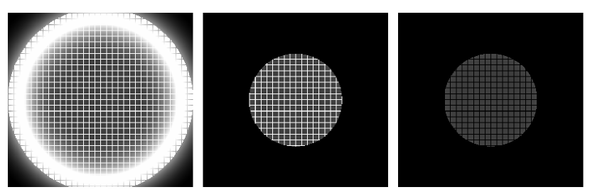
where is the aperture illumination function from equation (2-1), and is the Fourier transform of the mask shape function which describes the occulting mask’s departure from complete transparency (see Figure 1, left panel). Equation 4-1 expands to
| (4-2) |
In the interior of the Lyot plane the quantity (which is the field strength for the coronagraphic ASF of a monolithic mirror telescope with the same overall aperture geometry as our segmented telescope, but without segment gaps) is negligibly small or zero, depending on the coronagraph design. Dropping this term in the interior of the Lyot pupil, we obtain
| (4-3) |
The equivalent width of the function is . For 30 m, and a typical segment size 1 m, the condition holds (in Yaitskova & Sivaramakrishnan (2005) we show that a less restrictive condition, , is in fact good enough for the following calculation to be valid). In the highly-segmented telescope case this inequality holds, and the cited work demonstrates that the convolution does not depend on the segmentation geometry, but only on the ratio of the gap width to the segmentation periodicity, :
| (4-4) |
An unapodized, unsegmented, undersized Lyot stop with an aperture function is used to remove the bright annulus of light on the borders of the Lyot pupil (Figure 1, middle panel). We note that , i.e., the Lyot pupil on this monolithic mirror telescope is contained within the aperture itself.
We also introduce a reticulated mask that blocks out the bright segment gaps in the Lyot pupil (Figure 1, right panel). This corresponds to a mask function . Our Lyot stop is therefore written as . The field immediately after our Lyot stop then becomes
| (4-5) |
Comparing this equation with the expression in equation (2-1) for the segmented aperture illumination itself, we notice that coincides with the complex amplitude for the segmented telescope with the field strength reduced by factor (in the interior of the Lyot stop). If the initial illumination of the aperture is uniform, and there are no residual phase errors (i.e., the segments are co-phased, and wavefront correction by adaptive optics is perfect), we can apply the techniques of Yaitskova et al. (2003) to describe .
5. The Coronagraphic PSF
The Lyot field described by equation (4-5) produces a segmented telescope coronagraphic ASF
| (5-1) |
( being the ASF corresponding to the unsegmented Lyot stop , the two-dimensional Dirac delta function, and the Fourier transform of ).
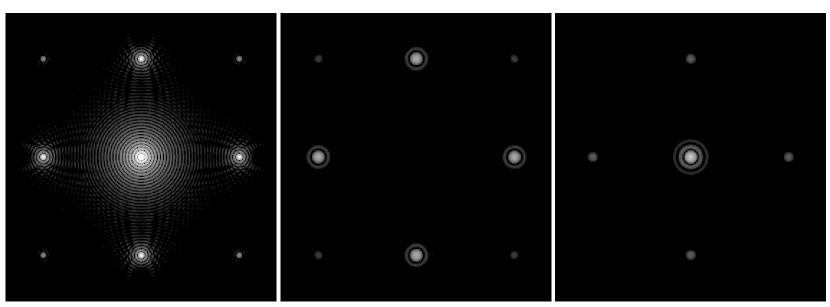
The on-axis coronagraphic image, (Figure 2, right), which results from using a reticulated Lyot stop that masks out the segment gaps, is reduced by factor from the PSF of the segmented telescope (Figure 2, left) on which the Lyot coronagraph is applied. The PSF of the segmented telescope with gaps (Figure 2, left) contains higher-order ‘satellite’ diffraction peaks (in addition to the central dominant peak) located on a grid with an angular periodicity that is inversely proportional to the segment center-to-center separation (i.e., the segment spatial periodicity). In there is also a broadening of the central and higher-order diffraction peaks due to the undersized Lyot stop diameter relative to the original entrance aperture diameter. The intensity of the higher order diffraction peaks with the reticulated Lyot stop is down a factor of from those same satellite peaks without the reticulated Lyot stop. The intensity of the central peak of the PSF before the coronagraph (the Strehl ratio, if a monolithic aperture is the reference unaberrated PSF) is . Hence the intensity of the central peak after the coronagraph is relative to the monolithic aperture’s PSF peak. For a 10 mm inter-segment gap, the value of this expression is . The intensity of the brightest peaks for a hexagonally segmented aperture is relative to the peak of the unsegmented aperture’s PSF.
On a coronagraph with a matched reticulated Lyot stop, this ratio is . For the same example as before (a 30 m telescope with segments and a 10 mm inter-segment gap), . Analogous estimates can be made for the diffraction peaks of any order. The intensity around the peaks can also be obtained as the intensity of the PSF for the segmented telescope, but again, reduced by the factor .
The coronagraphic PSF of a segmented telescope is . A detailed analysis of the contrast and morphology of coronagraphic PSFs on telescopes with hexagonal segmentation will be presented in Yaitskova & Sivaramakrishnan (2005).
As Figure 2 shows, the coronagraphic PSF with the reticulated Lyot stop has a central core and faint satellite spots. This PSF is suitable for studying extended objects such as protoplanetary disks. In contrast, using a simple Lyot stop creates better suppression of the core of the PSF, but transmits the satellite spots caused by primary mirror segmentation.
References
- Aime & Soummer (2003) Aime, C. & Soummer, R. 2003, EAS Publications Series, Volume 8, 2003. Astronomy with High Contrast Imaging, Proceedings of the conference held 13-16 May, 2002 in Nice, France. Edited by C. Aime and R. Soummer, 8
- Aime & Soummer (2004) —. 2004, EAS Publications Series, Volume 12, 2004. Astronomy with High Contrast Imaging, Proceedings of the conference held 99-99 October, 2003 in Nice, France. Edited by C. Aime and R. Soummer, 12
- Aime et al. (2001) Aime, C., Soummer, R., & Lopez, B. 2001, A&A, 370, 680
- Angel (1994) Angel, J. R. P. 1994, Nature, 368, 203
- Bracewell (1986) Bracewell, R. N. 1986, The Fourier Transform and its Applications (London: McGraw Hill)
- Chanan & Troy (1999) Chanan, G. & Troy, M. 1999, Appl. Opt., 38, 6642
- Dierickx & Gilmozzi (2000) Dierickx, P. & Gilmozzi, R. 2000, in Proc. SPIE Vol. 4004, p. 290–299, Telescope Structures, Enclosures, Controls, Assembly/ Integration/Validation, and Commissioning, Thomas A. Sebring; Torben Andersen; Eds., 290–299
- Golimowski et al. (1995) Golimowski, D. A., Nakajima, T., Kulkarni, S. R., & Oppenheimer, B. R. 1995, ApJ, 444, L101
- Kuchner & Traub (2002) Kuchner, M. J. & Traub, W. A. 2002, ApJ, 570, 900
- Lloyd & Sivaramakrishnan (2004) Lloyd, J. P. & Sivaramakrishnan, A. 2004, ApJ, in press
- Lyot (1939) Lyot, B. 1939, MNRAS, 99, 580
- Makidon et al. (2000) Makidon, R. B., Sivaramakrishnan, A., Koresko, C. D., Berkefeld, T., Kuchner, M. J., & Winsor, R. S. 2000, in Proc. SPIE Vol. 4007, p. 989–998, Adaptive Optical Systems Technology, Peter L. Wizinowich; Ed., 989–998
- Nakajima et al. (1995) Nakajima, T., Oppenheimer, B. R., Kulkarni, S. R., Golimowski, D. A., Matthews, K., & Durrance, S. T. 1995, Nature, 378, 463
- Nelson (2000) Nelson, J. E. 2000, in Proc. SPIE Vol. 4004, p. 282–289, Telescope Structures, Enclosures, Controls, Assembly/ Integration/Validation, and Commissioning, Thomas A. Sebring; Torben Andersen; Eds., 282–289
- Oppenheimer et al. (2003) Oppenheimer, B. R., Sivaramakrishnan, A., & Makidon, R. B. 2003, in The Future of Small Telescopes In The New Millennium. Volume III – Science in the Shadow of Giants, 155–+
- Sivaramakrishnan et al. (2001) Sivaramakrishnan, A., Koresko, C. D., Makidon, R. B., Berkefeld, T., & Kuchner, M. J. 2001, ApJ, 552, 397
- Sivaramakrishnan et al. (2004) Sivaramakrishnan, A., Makidon, R. B., Soummer, R., , Macintosh, B. A., Poyneer, L., Troy, M., Chanan, G. A., Lloyd, J. P., Perrin, M. D., Graham, J. R., & Sheinis, A. I. 2004, in Proc. SPIE, Vol. 5490, Advancements in Adaptive Optics, eds. R. Ragazzoni & B. Ellerbroek
- Yaitskova et al. (2003) Yaitskova, N., Dohlen, K., & Dierickx, P. 2003, Optical Society of America Journal, 20, 1563
- Yaitskova & Sivaramakrishnan (2005) Yaitskova, N. & Sivaramakrishnan, A. 2005, in preparation