The influence of rotation in radiation driven wind from hot stars: New solutions and disk formation in Be stars.
Abstract
The theory of radiation driven wind including stellar rotation is re-examined. After a suitable change of variables, a new equation for the mass loss rate is derived analytically. The solution of this equation remains within confidence when compared with numerical solutions. Also, a non-linear equation for the position of the critical (singular) point is obtained. This equation shows the existence of an additional critical point, besides the standard m–CAK critical point. For a stellar rotation velocity larger than 0.7 – 0.8 , there exists only one critical point, located away from the star’s surface. Numerical solutions crossing through this new critical point, are attained. In these cases, the wind has a very low terminal velocity and therefore a higher density wind. Disk formation in Be stars is discussed in the frame of this new line driven stellar wind solution.
1 Introduction
The theory of radiation driven winds has been very successful describing the observed terminal velocities and mass loss rates from hot stars. After the pioneering work of Castor, Abbott and Klein (1975, hereafter CAK) who realized that the force due to line absorption in a rapidly expanding envelope can be calculated using the Sobolev approximation (Castor 1974). They developed a simple parameterization of the line force and were able to construct an analytical wind model.
Simultaneously and independently, Friend and Abbott (1986) and Pauldrach, Puls and Kudritzki (1986) (hereafter FA and PPK, respectively) calculated the influence of the finite cone angle correction on the dynamics of the wind. They found a better agreement between the improved or modified theory (hereafter m-CAK) and the observations for both (mass loss rate) and (terminal velocity) in a large domain in the Hertzsprung-Russell diagram. Furthermore, Kudritzki et al. (1989, hereafter KPPA) developed analytical formulae for the localization of the critical point, mass loss rate and terminal velocity with an agreement within 5% for and 10% for , when compared with numerical calculations.
The influence of the star’s rotation was investigated by Castor (1979) and Marlborough and Zamir (1984). Both studies concluded that the effect of adding a centrifugal force term in the CAK equation results in a lower terminal velocity wind, but the mass loss rate is not substantially affected. Similar results were founded by FA and PPK.
Concerning Be Stars, the m-CAK theory gives a good description for the polar wind, but it fails to account for a slowly accelerating flow, like the one in the equator of Be stars. Therefore several additional mechanisms has been proposed, based on the radiatively driven wind theory to explain the equatorial flow of these objects. The influence of magnetic fields and rotation were studied by Friend and McGregor (1984, see review from Cassinelli 1998). A model with azimuthal symmetry, rotation and viscous force was developed by de Araujo et al. (1994) and Koninx & Hearn (1992) incorporated sound waves in the wind dynamics of Be stars. A model driven mainly by thin lines has been proposed by de Araujo (1995), he obtains an outflow with a shallow expansion and a large mass flux when the line force parameters are considered as free and not in a self-consistently mode (Pauldrach 1989). A 2-D hydrodynamical model from Bjorkman and Cassinelli (1993) and Owocki et al. (1994) concluded that a meridional current may be responsible for the concentration of matter towards the equator, forming a wind compressed disk (”WCD”). An assumption of the WCD model, that the line–force is strictly central was released by Owocki, Cranmer & Gayley (1996). They conclude that non–radial line–force components together with gravity darkening effects can inhibit the formation of a WCD structure.
Despite all the efforts, the most important problem that pervades all these models, is the strong equatorial expansion that they exhibit. Not only the terminal velocity is too high ( 1000 ) but also there is a sharply increase of the velocity field. The fitting of observed line profiles requires terminal velocities of about 200 or less (Poeckert & Marlborough 1978), while from Fe II line profiles, Hanuschik (1994, see also Waters & Malborough 1994) concluded that the disk expansion velocity must not be much larger than the Doppler width.
When rapid rotators are theoretically studied (such as Be stars), many authors have reported the appearance of numerical problems when the rotational speed is about 0.8 times the break-up speed, see e.g., FA, Poe and Friend (1986), de Araujo and de Freitas Pacheco (1989), Boyd & Marlborough (1991).
In view of the previous comments our purpose is to perform a re-analysis including the rotational centrifugal force term in radiation driven wind theory.
In section 2, an analytical treatment with the inclusion of the star’s rotational speed is carried on. In section 3, after a suitable coordinate transformation, exact formulae for the location of the critical (singular) point(s) and for mass loss rate are obtained. The roots of the critical point function defines the number of singular (critical) points and their location. We show the existence of a new family of singular points in addition to the standard one (m–CAK solution family). A simple, approximative, treatment for the location of the singular point(s) and the value of the corresponding mass loss rate (eigenvalue) is introduced in section 4. Furthermore, in this section, numerical and analytical results for the standard m–CAK solution are compared, showing the high confidence of this analytical approximation. Section 5 is devoted to find a numerical solution from the momentum equation of the wind, that starts at the stellar and surface reaches infinity after passing through a critical point that belongs to this new family of singular points. Also a comparison between numerical and analytical result are performed in order to show the accuracy of this analytic treatment. Finally the applicability of this model to explain disk–formation in Be–Stars is discussed in section 7. Conclusions and future lines of research are summarized in section 8.
2 Hydrodynamic formulation
The standard model for radiation driven stellar winds considers one component isothermal fluid in a stationary regime with spherical symmetry, neglecting the effect of viscosity, heat conduction and magnetic field (CAK, FA, PPK). The continuity equation reads:
| (1) |
and the momentum equation is given by:
| (2) |
here is the fluid velocity, the velocity gradient, the mass density, is the star’s mass loss rate, the fluid pressure, , where is the star’s rotational speed at the equator, is the radiative acceleration caused by Thomson scattering in terms of gravitational acceleration and is the acceleration due to the lines. The standard parameterization of the line force (Abbott 1982, PPK, FA) is:
| (3) |
The coefficient is given by:
| (4) |
here is the thermal velocity of the protons, is the Thomson scattering absorption coefficient per density and is the electron number density in units of ,
| (5) |
is the dilution factor, is the correction factor (see appendix B) and all the other quantities have their usual meaning (see, e.g., PPK).
Introducing the following change of variables
| (6a) | |||||
| (6b) | |||||
| (6c) | |||||
where is the star’s radius and is the isothermal sound speed, i.e., .
The momentum equation (2) with the line force (3) becomes:
| (7) |
here
| (8a) | |||
| (8b) | |||
| (8c) | |||
| and | |||
| (8d) | |||
where is the escape velocity, and is defined by:
| (9) |
here is the helium abundance relative to the hydrogen, is the amount of free electrons provided by helium, is the atomic mass number of helium and is the mass of the proton.
The standard method for solving this non-linear differential equation (7) together with the constant (the eigenvalue of the problem) is imposing that the solution pass through the singular (critical) point (see CAK for details), together with a constrain on the optical depth integral:
| (10) |
Other authors prefer to use an equivalent lower boundary condition, e.g., setting the the density at the stellar surface to a specific value,
| (11) |
de Araujo et al. (1989) use , Friend & MacGregor (1984) use .
A critical point is located where the singularity condition, is satisfied:
| (12) |
At this specific point, regularity is imposed, namely:
| (13) |
3 Location of the Critical Point(s)
In this section, after a coordinate transformation we obtain a set of analytical equations for the eigenvalue and the location of the singular point. For the last one, we show, that a new family of singular points exist. We also prove, that the standard m–CAK solution vanishes for stars with high rotational velocity.
3.1 Coordinate transformation
3.2 The critical–point function
It is not possible to obtain the location of the critical point from this set of equations because we have only three equations and four unknowns (,, and ). But from equations (15a), (15b) and (15c), we obtain a function, , defined by:
| (18) |
where is defined by
| (19) |
The root(s) of this function gives the location of the critical (singular) point(s) .
Notice that no approximation whatsoever has been used in the derivation of the above equations.
In order to know the range of the variable for a typical hot–star wind, we have performed a full numerical calculation, i.e., we solve without any approximation: the momentum equation (7) together with the singularity condition, equation (12), the regularity condition, equation (13), and a lower boundary condition: equation (10) or equation (11). Our typical star is an star with the following stellar parameters: , , and , while the line force parameters are: , and . Figure 1 shows the behavior of , which ranges between and , for the whole wind. This figure also shows two –field approximations (see below).
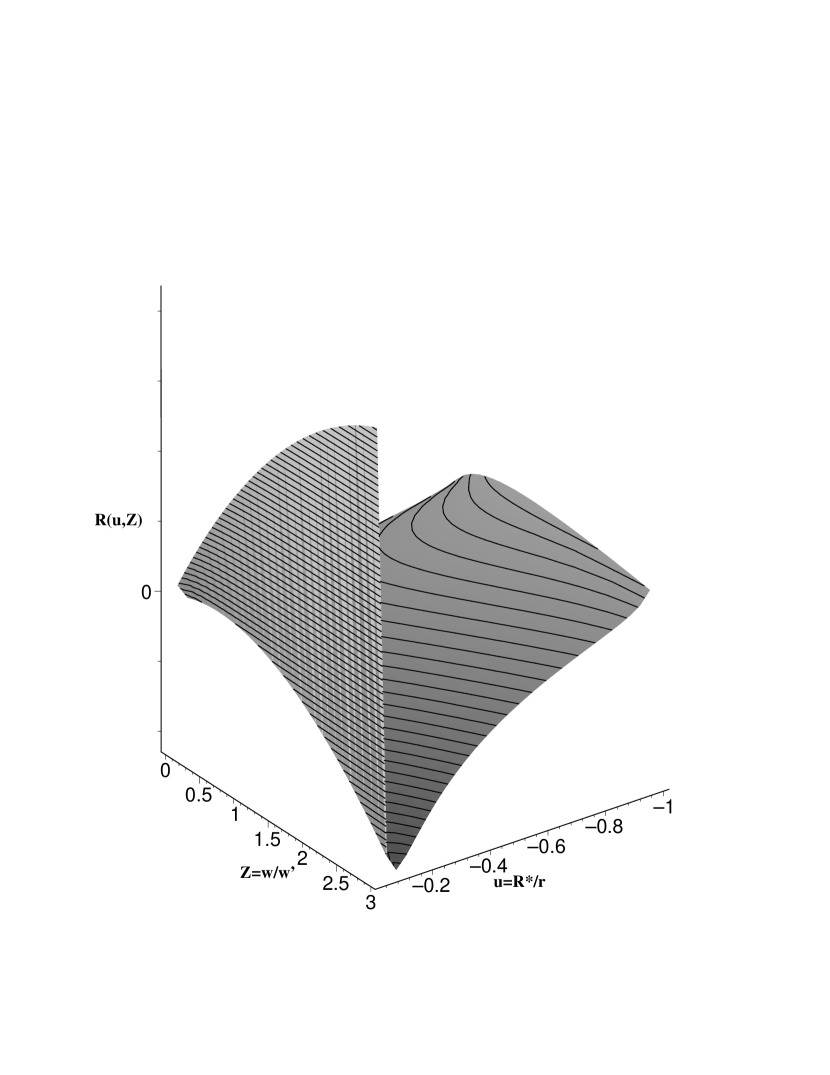
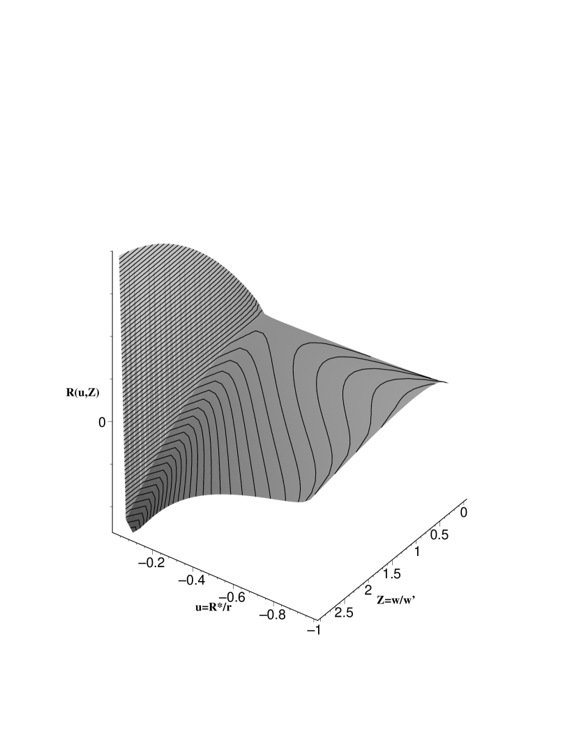
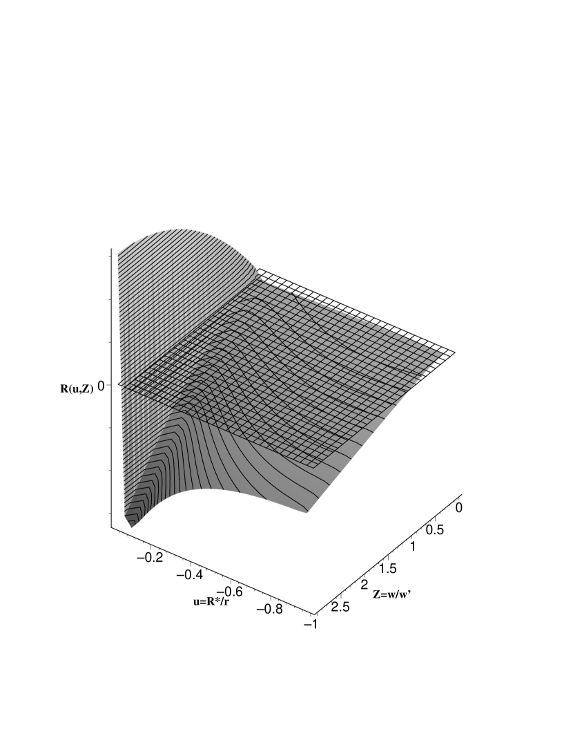
Knowing now the range of the variable we may plot in terms of and . Figures 2 and 3 show two different visualization of the function for this star with . Figure 4 shows, besides , the zero–plane defined by . Thus, the root(s) of is(are) the curve(s) defined by the intersection of this surface with the zero–plane. Figure 4 shows both surfaces, their intersections are two families of critical points. The standard m–CAK family of solutions (CAK: locus of singular points) is located in the zone defined approximately by: and .
When full numerical calculations are carried on, the lower boundary condition, eq. (10) or eq. (11), fixes one point in this family of critical points and in this way an unique numerical solution for the m–CAK wind is achieved.
As the rotational velocity of the star increases, this m-CAK locus does not longer intersects the zero–plane because the function becomes negative in this region, as figure 5 shows for the case . Thus, standard m–CAK solution does not exist for stars with highly rotational speeds, e.g., Be–Stars. This is the reason why many authors (see .e.g., de Araujo et al. 1994, Boyd & Marlborough 1991, FA) have reported numerical difficulties in finding the location of the singular point for high rotational velocities, it does not exist.
Furthermore, inspecting carefully figure 5, a new family of solution is found in the region defined approximately by and . This family of solutions has been always present, even for lower rotational velocities, see the case of figure 4.
When both families of solutions are present, e.,g., for not highly rotational speeds, the family that satisfies the lower boundary condition, eq. (10), is the m–CAK locus. A study about the existence of a physical solution, that crosses through a singular point that belongs to the new family, when both families are present, is the scope of a forthcoming article.
We are now ready to look for numerical solutions, that starts at the stellar surface, then crosses through a singular point located at this new locus and reaches infinity, for the special case when only the new family is present, e.g., for highly rotational speeds. We will perform this task in section 6.
Before, in the next section, a simple approximation for the function is introduced. This approximation allows an easy location of both, the standard and the new singular point.
4 Approximative Treatment
In this section we develop an approximative treatment of the critical point function . After introducing a –field approximation, the function transform to . The zeros (roots) of this approximative function are the location of the critical points. Knowing the location of the critical point(s) it is straightforward to calculate the eigenvalues or equivalently the mass loss rate of the star. This approximative calculations are in much better agreement with full numerical calculations than previous analytical treatments and includes the influence of star’s rotation.
4.1 The approximative critical point function
From numerical calculations, PPK found that the velocity field, for stars with effective temperatures between and can be approximated to the so called –field approximation, namely:
| (20) |
with . This relationship is broadly used for stellar wind diagnostics and it is justified a posteriori by the quality of the results achieved (Kudritzki & Puls, 2000).
Applying this approximation for the variable, it becomes:
| (21) |
Figure 1 shows the vs. profile from numerical calculations and the behavior of eq. (21) for two different values of the parameter ( and ). This approximation holds, for the variable, up to () for and up to () for .
Thus, replacing eq. (21) in eq. (18), transform to , defined as:
| (22) |
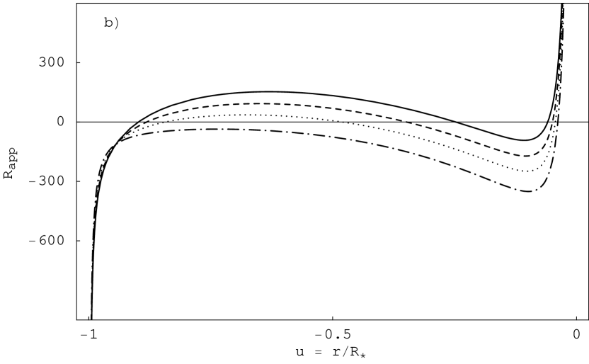
The function transforms to , and its behavior is shown in figure 6 for different values of the free–parameter . Once the root(s) of in the interest domain (interval or ) is(are) obtained, the values of and are obtained from equations (16) and (17) respectively.
4.2 An Example: CAK with Rotation
It could be thought, that this simple case has only an academic interest, but as we shall see later, that these results contribute to the understanding of the dynamic of rapid rotators.
For the CAK model (with ), the functions are: , and , then the function reads:
| (23) |
this is a fourth order polynomial in . Contrarily to the expected, the non–rotational case, does not depend neither on the stellar parameters: , , , nor on the line–force parameters (, , ), it explicitly depends on . Furthermore, for the rotational case it depends on the stellar parameters and the free-parameter , but not on the line-force parameters.
CAK and KPPA have shown that the behavior of the velocity profile is given approximately by:
| (24) |
This results was obtained from approximate solutions for a non–rotating CAK wind, (see CAK eq.[47] or KPPA eq.[24]). This relationship corresponds to a –field with . Figure 7 shows the function , for this test star, for different values of and . From this figure, it is clear that only one critical point exists in the domain of interest. Bjorkman (1995) arrived to the same conclusion in his topological study of the non-rotating CAK model.
As the rotational speed increases, figure 7 shows that the location of the CAK singular point is shifted downstream, this is the same conclusion reached by Castor (1979) and Marlborough & Zamir (1984).
The zero () of equation (23) in the interval is giving by the analytical formula:
| (25) |
where the t–coefficients are:
| (26a) | |||||
| (26b) | |||||
| (26c) | |||||
| (26d) | |||||
| (26e) | |||||
| (26f) | |||||
| (26g) | |||||
| (26h) | |||||
| (26i) | |||||
For the simple case of , a straightforward and exact solution for equation (18) is
| (27) |
and after applying the approximation with , the critical point is founded at or , as CAK and KPPA previously obtained using different approaches.
Table 1 shows the accuracy of this analytical approximation. Columns 2–4 and 6–8 show, for different values of parameter, the location of the singular point (in terms of ), and mass loss rates (in units of ) respectively. For comparison, columns 5 and 10 give the values of and from full numerical calculations111Here, full numerical calculation solves equations (7), (12), (13) and the lower boundary condition equation (10).. For the non–rotational case, the best values is confirming the results of previous analyses. KPPA cooking recipe for (see KPPA eq. [27]) gives , same as the non–rotational case with . While the value of the mass loss rate is almost independent of the value of , the location of the critical point is very sensitive to the value of , but in the presence of rotation, this sensitivity disappears. The reason is that here the rotational term (third term in equation 23) is the dominant one, and therefore the dependence on becomes minimal. Furthermore, the larger the rotational speed, the larger is the value that best fits the numerical calculations.
4.3 The m-CAK Standard Solution
Now we analyse the influence of the finite cone-angle effect. The main difference between this approach and the one of KPPA is that they introduced the –field approximation before calculating the derivatives of the singularity and the regularity conditions. Therefore they could not obtain the equations (15a), (15b) and (15c). In fact, the last two of them become the same in the KPPA approximation.
4.3.1 OB stars
In order to obtain the critical point and the mass loss rate it is necessary to know the value of . As discussed above, PPK found that a value of is appropriate for –Stars. In figure 8, same as fig. 1 but here in the region near the photosphere, the ’+’ symbol indicates the location of the critical point at the profile. The –field approximation with intersects almost exactly this location showing that for this type of stars is a fairly good approximation to calculate the critical point location and the mass loss rate.
Table 2 shows a comparison between analytical and full numerical calculations for the test star (see stellar and line–force parameters in section 3.2). The best agreement for both analytical, and , with the numerical calculation occurs for . Furthermore, this predicted analytical values agree much better with the numerical calculations than the values given by the ’cooking recipe’ from KPPA. This recipe gives for the non–rotational case: and (with ). When the analytic approximation of KPPA is compared with numerical calculations, it is found that the values of are always smaller than the numerical values. For the non–rotational case, our approximation match almost exactly the values of the numerical calculations, but for rotational cases it still shows values slightly less than the numerical ones.
4.3.2 Cental Stars of Planetary Nebulae
Radiative driven stellar wind are also present in Cental Stars of Planetary Nebulae (CSPN), i.e., for objects where the effect of photospheric extension is important. Pauldrach et al. (1988) have computed radiative driven wind models along evolutionary tracks for these objects. They found that the the predicted terminal wind velocities are in agreement with the observational data, while the mass loss rate are in qualitative agreement.
In their non–LTE analysis of CSPNs, Kudritzki et al. (1997) used a –field approximation for the velocity, finding that is the best value for these stars (see table 1 from Kudritzki et al. 1997). Table 3 shows a comparison between analytical and numerical calculations for one of the models of Pauldrach et al. (1988). The stellar parameters for this model are: , , and , line–force parameters are: , and . This analysis confirms that a value of is a fairly good one for non–rotational CSPN, but as the rotational velocity increases a slightly larger value must be assumed.
In this section, we have developed an analytical treatment for the location of the critical point (standard m–CAK) and mass loss rate that improves (includes rotation) previous investigations, and has about 1% confidence when is compared with full numerical calculations.
5 Analytical Treatment of the New Wind Solution.
In previous sections, the existence of a new family of solutions, that are different of the standard m-CAK, has been established from the properties of the function. In this section we study the approximate function to get information about the location of the singular point and the mass loss rate.
5.1 Critical Points
5.1.1 The Standard m–CAK Critical Point
Figure 9 shows , with , for an star for different values of the star’s rotational speed for both models, CAK and m-CAK. From this figure it is clear that the inclusion of the finite disk correction factor in the wind momentum equation (7), ’twist’ the function to . It is evident from this result that while displays only one root in the interest domain, the number of roots of depends on the rotational velocity.
For non–rotational cases (figure 9a) the CAK critical point shifts to a location close to the stellar surface, this is the standard m–CAK critical point. As the rotational speed increases, the location of the m-CAK singular point is shifted downstream (FA, PPK), but differently as in the CAK case, it occurs up to certain rotational speed.
In order to have a better picture of the approximation we have to recall the function (see, e.g., figure 4). This is a surface in the phase–space defined by the independent coordinates and . The approximation is a vertical–plane in this phase–space that cuts the –surface defined by equation (18). The projection of this intersection–curve over the vertical plane is the function showed in figure 9.
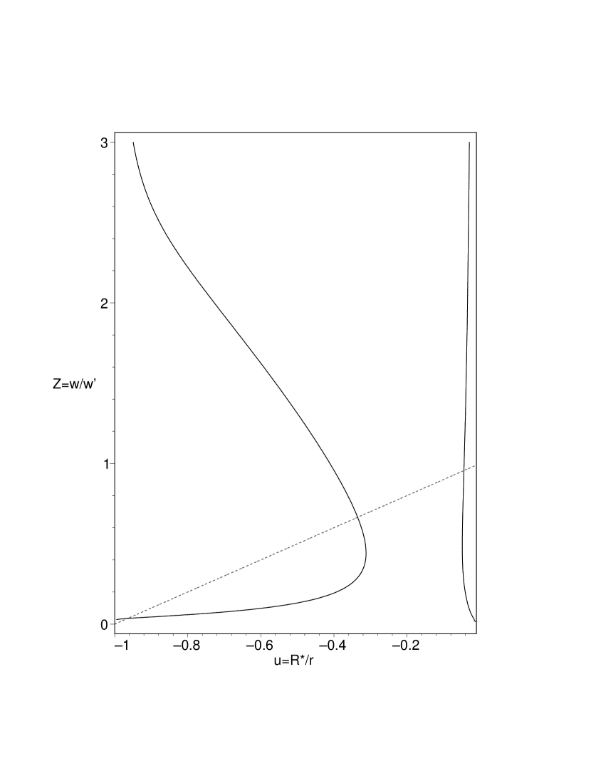
Figure 10 is a contour plot of the –surface at the zero–plane, the plane. Both continuous–lines correspond to the two families (loci) of singular points, discussed in section (5.1), while the dashed–line is the –field approximation (). This approximation cuts the standard m–CAK family in two points. The standard m–CAK solution passes through the first intersection point (nearest to stellar surface, ) and not through the second intersection point, as a result of imposing the lower boundary condition equation (10). The second intersection point is only a consequence of the –field approximation and a solution (if exists) that passes only through this point probably have no physical meaning for radiation driven winds.
5.1.2 The New m–CAK Critical Point
In addition to the standard m–CAK critical point, figure (9) and figure 10 shows a second critical point (root of ), the last intersection–point. As the rotational speed increases, for this star, the standard m-CAK critical point now disappears of the integration domain when (fig. 9d, see also figure 5). In this case, the CAK critical point is shifted far downstream in the wind. At the critical point, , the function , so is almost the same for CAK and m-CAK models (see equations 22 and 23). Thus, for the fast–rotational case, equation (25) gives a very good approximation for the location of the critical point and therefore the mass loss rate, too.
We conclude that the CAK model with rotation is applicable for high–rotational velocities to calculate the mass loss rate and the location of the singular point of the m–CAK model.
Because we are now interested in stars with high rotational velocities, from now on our test star will be a typical Star with following stellar parameters: , , (Sletebak et al. 1980) and line force parameters: , , . For this star, figure 11 shows for two different values of . In both cases, as the rotational speed increases, goes to a scenery where there is only one critical point, the new one. For , a lower value of the rotational speed is required to get to this situation, i.e., , while for , the required is . This last value is lower than the required for the Star (see fig. 9).
In order to know all the families of solutions, a topological analysis is needed, similar to the analysis performed for the non–rotating CAK model by Bjorkman (1995). As a first step in order to learn about this new solution, we carry on numerical calculations only for the fast–rotational case, i.e., the case where only one root of the function exists, the new critical point. It is not clear yet, that a wind solution should cross only through one critical point or there are solutions that have to cross through more than one critical points as, e.g., in the magnetic wind model of Friend & MacGregor (1984).
6 Numerical Results
It has been established in the previous sections that in a fast–rotational case, the standard m–CAK critical point vanishes and there exist a second critical point. In this section we will obtain full numerical solutions, that starting at the star’s surface reaches infinity passing through this new critical point.
6.1 The Numerical Method
In order to solve the non–linear wind momentum differential equation (7) for a fast–rotational case, we will not use the ’standard’ numerical method, i.e., once the singular point location, its velocity and velocity gradient are approximatively obtained, direct integration up and downstream are performed (e.g., using Runge-Kutta or Burlish-Stoer methods). After this process has been done, the lower boundary condition is calculated and the whole procedure starts again until convergence is achieved.
Instead, we use here a finite-difference method, modified for handling singular points (Nobili & Turolla 1989). This method uses a trial solution as its initial guess. This initial solution then relaxes, using the Newton method, towards the numerical solution (see Nobili & Turolla 1989 for details). The main advantage of this method is the fact that it is not necessary to give a priori the location of the critical point, as the standard method requires, so no guess value for is needed for solve the momentum equation.
6.2 The Fast Solution
6.3 The Slow Solution
We have solved numerically the fast–rotational case for . This new solution is denser than the fast solution (m–CAK) and we call it hereafter slow solution due to the lower value of the terminal velocity achieved, figure 12 also shows this profile (continuous–line). The location of the critical point is at , confirming the approximative calculations of the preceding sections, that the critical point is located far away in the wind. The terminal velocity of this new solution is . This value is a factor 4 lower than the standard m–CAK solution (the fast–solution, dashed–line in figure 12). The mass loss rate is , approximately twice the value of the non–rotational case.
6.3.1 The Approximation
Figure 13 shows versus from full numerical calculations (continuous line). In addition, the location of the critical point is drawn with a ’+’ symbol in this figure. The approximation (a straight line in this figure) is also plotted for two different values of the parameter . The line with intersects close to the location of the critical point, showing that for fast–rotational cases a value of matches better the location of the critical point and the mass loss rate (eigenvalue).
6.3.2 Functions and
In order to validate the function, we have plotted in figure 14 the function from the results of the full numerical calculations (continuous–line) and compared it with the functions for two different values of the parameter (dashed–lines). The behavior of and in the region far away in the wind () is similar for both values of , confirming that, also for this new solution, the last root of the approximate function gives an accurate value for the location of the critical point, , and through eq. (16) and eq.(17) the eigenvalue, , for the fast–rotational case.
6.4 and from slow solutions.
As de Araujo (1994) and Stee at al. (1995, and references therein) argued, it is possible to obtain equatorial solutions with lower terminal velocities when the wind is driven mainly by thin lines, e.g., using a lower value of the line force parameter . Thus, we have investigated the value of that makes that the standard m–CAK critical point disappears remaining only the slow solution.
Table (4) summarises the value of this minimum rotational velocity from the function for the existence of the slow solution. The values of and are taken from de Araujo(1994) and has been used. The values of and are coming from full numerical solutions. This result suggests that in order to obtain a better modeling of this slow–solution a self–consistent calculation (Pauldrach 1989) of the line force parameters is necessary. This table (4) shows, that the thinner the lines drive the wind (lower ), the lower is the required rotational velocity for slow solution and therefore the lower is the terminal velocity and mass loss rate. This table also shows a weak dependence of the –parameter on the minimal rotational velocity.
7 Disk Formation in Be Stars.
For our model is natural to think that a fast–rotating star can have both wind solutions, e.g., Be Stars. The polar direction is equivalent to the non–rotational case, while the equatorial flow corresponds to the fast–rotational case. In figure 15 the density profile for both directions, i.e., polar (dashed–line) and equatorial (continuous–line) are plotted against the inverse radial coordinate .
The ratio between the equatorial and polar densities are about a factor very close to the star’s surface but mainly a factor for the whole wind. This density quotient value is still a factor 10 smaller than the observational values. The disk aperture angle occurs when the m–CAK critical point disappears from the function, so this angle will depend strongly on the assumed value of the line–force parameter . A detailed ’2-D’ (latitude dependent) velocity and density profile and line formation is the subject of a forthcoming article.
8 Conclusions
After a suitable change of coordinates, we show that besides the standard m–CAK critical point there exists a second one when the star’s rotational speed is taken into account for a hot star with radiation driven wind. Using a simple –field approximation we developed an analytical description for the location of the critical point and the value of the mass loss rate of the star. Our solution remains within a 1% confidence when compared with numerical calculations. This point is very important when trial solutions for numerical codes are selected.
For the case of extreme high rotational speed (applied to a Be star), we have studied new solutions. Here exists only one critical point and numerical wind solutions were obtained. This new solution gives very slow terminal velocities (in the range to , depending on the assumed values of the line force parameters) and the density of the wind is about 10 times denser than the standard m–CAK wind solution. These results indicate that new wind solution of the standard m–CAK model may be important in forming the disk in Be Stars. But to improve this model for Be stars, it is necessary that the following effects be to taken into account: the dependence of the radius and temperature as a function of rotational speed and latitude, a self-consistent treatment of the line force parameters, a detailed study of the influence of the boundary conditions, a re-analysis of angular momentum conservation (including viscous forces) and the (ignored here) influence of magnetic fields.
Currently a detailed study of the topology of the singular points is underway. There are probably more solutions which involve more than one singular point as the case of magnetic fields.
Appendix A Coordinate Transformation.
Here the basic steps toward equations (15a), (15b) and (15c) are outlined. The reader should keep in mind the original derivation by CAK.
After using the new coordinate and , some derivative relation of the correction factor (see appendix B) and defining:
| (A4) |
where
| (A5) |
the singularity condition () reads:
| (A6) |
here,
| (A7) |
and is a function defined in appendix B.
The regularity condition () transform to:
| (A8) |
with
| (A9) |
Appendix B The Correction Factor
The Correction Factor is defined by:
| (B1) |
where and . Integrating B1 and changing the variables from to (, , where is the thermal velocity), the finite disc correction factor transform to:
| (B2) |
where . Due to the fact, that depends on and only the quotient , so defining as:
| (B3) |
we can re–write as:
| (B4) |
The partial derivatives of with respect to are related to via the chain rule, namely:
| (B5) |
| (B6) |
| (B7) |
References
- (1) Abbott, D.C., 1982, ApJ, 259, 282
- (2) Boyd, C.J. and Marlborough, J.M., 1991 , ApJ, 369, 191
- (3) Bjorkman, J.E., 1995, ApJ, 453, 369
- (4) Bjorkman, J.E. and Cassinelli, J.P., 1993, ApJ, 409, 429
- (5) Castor, J.I., 1974, ApJ, 183, 273
- (6) Castor, J.I., 1979, Mass Loss and Evolution of O-Type Stars, IAU Symp 83, eds. Conti,P.S., and de Loore, C.W., Dordrecht: Reidel, 175
- (7) Castor, J.I., Abbott,D.C. and Klein,R. 1975, ApJ, 195, 157
- (8) Cassinelli, J., 1998, B[e] stars : Proceedings of the Paris workshop held 9-12 June, 1997. Edited by A. M. Hubert and C.Jaschek. Dordrecht; Boston: Kluwer Academic Publishers, (Astrophysics and Space Science library; v. 233), p.177
- (9) de Araujo, F.X., 1995 , A&A, 298, 179
- (10) de Araujo, F.X. and de Freitas Pacheco, J.A., 1989, MNRAS, 267, 501
- (11) de Araujo, F.X., de Freitas Pacheco, J.A. and Petrini, N., 1994 ,MNRAS, 267, 501
- (12) Friend, D. and Abbott,D.C., 1986, ApJ, 311, 701
- (13) Friend, D. and MacGregor,K.B., 1984, ApJ, 282, 591
- (14) Hanuschik, R. W., 1994, in Pulsation, Rotation and Mass Loss in Early-type Stars,IAU symposium 162, Eds L.A. Balona, H.F. Henrichs and J.M.Contel (Kluwer Academic Publishers, Dordrecht), p.265
- (15) Koninx, J.P.M. and Hearn, A.G., 1992, A&A, 263, 208
- (16) Kudritzki,R.P., Pauldrach, A., Puls,J. and Abbott,D.C., 1989, A&A, 219, 205
- (17) Kudritzki,R.P. and Puls,J., 2000, ARA&A38, 613
- (18) Kudritzki,R.P., Mendez,R.H., Puls,J. and McCarthy,J.K., 1997, Planetary nebulae, IAU Symp. 180, eds. H.J. Habing and H.J.G.L.M. Lamers. Dordrecht: Kluwer Academic Publishers.
- (19) Nobili, L. and Turolla, R., 1988, ApJ333, 248
- (20) Marlborough, J.M. and Zamir, M., 1984, ApJ, 276, 706
- (21) Owocki, S.P., Cranmer, S.R. and Blondin, J.M., 1994, ApJ, 424, 887
- (22) Owocki, S.P., Cranmer, S.R. and Gayley, K.G., 1996, ApJ, 472, 115
- (23) Pauldrach, A., 1989, A&A, 183, 295
- (24) Pauldrach, A., Puls, J., Kudritzki, R.P., Mendez, R.H. and Heap, S. R. 1988, A&A, 207, 123
- (25) Pauldrach, A., Puls,J. and Kudritzki,R.P., 1986, A&A, 164, 86
- (26) Poe, C., and Friend, D., 1986, ApJ, 311, 317
- (27) Poeckert, R. and Marlborough, J.M., 1978, ApJ, 220, 940
- (28) Waters, L.B.F.M. and Marlborough, J.M., 1994, in Pulsation, Rotation and Mass Loss in Early-type Stars,IAU symposium 162, Eds L.A. Balona, H.F. Henrichs and J.M.Contel (Kluwer Academic Publishers, Dordrecht), p.399
| Numeric | Numeric | ||||||||
|---|---|---|---|---|---|---|---|---|---|
| 0.0 | 1.500 | 2.000 | 3.000 | 1.562 | 3.074 | 3.086 | 3.093 | 3.083 | |
| 0.3 | 6.125 | 6.211 | 6.537 | 6.186 | 3.127 | 3.128 | 3.131 | 3.128 | |
| 0.5 | 10.175 | 10.220 | 10.398 | 10.100 | 3.163 | 3.165 | 3.167 | 3.164 | |
| 0.7 | 14.233 | 14.264 | 14.385 | 14.507 | 3.201 | 3.202 | 3.205 | 3.203 | |
| 0.9 | 18.295 | 18.318 | 18.409 | 18.555 | 3.240 | 3.241 | 3.243 | 3.243 | |
| Numeric | Numeric | ||||||||
|---|---|---|---|---|---|---|---|---|---|
| 0.0 | 1.026 | 1.034 | 1.084 | 1.033 | 2.089 | 2.131 | 2.364 | 2.129 | |
| 0.3 | 1.027 | 1.035 | 1.088 | 1.036 | 2.235 | 2.280 | 2.520 | 2.280 | |
| 0.5 | 1.029 | 1.038 | 1.098 | 1.040 | 2.566 | 2.618 | 2.903 | 2.623 | |
| 0.7 | 1.036 | 1.048 | 1.129 | 1.051 | 3.372 | 3.437 | 3.782 | 3.452 | |
| Numeric | Numeric | ||||||||
|---|---|---|---|---|---|---|---|---|---|
| 0.0 | 1.042 | 1.069 | 1.102 | 1.074 | 4.638 | 4.881 | 5.140 | 4.916 | |
| 0.3 | 1.044 | 1.073 | 1.108 | 1.080 | 4.882 | 5.141 | 5.418 | 5.189 | |
| 0.5 | 1.050 | 1.082 | 1.123 | 1.092 | 5.424 | 5.716 | 6.024 | 5.791 | |
| 0.7 | 1.064 | 1.107 | 1.163 | 1.126 | 6.678 | 7.021 | 7.372 | 7.137 | |
| ( ) | ( ) | |||||||
|---|---|---|---|---|---|---|---|---|
| 0.5 | 0.3 | 0.88 | 0.87 | 0.86 | 454 | 6.86 | ||
| 0.4 | 0.7 | 0.82 | 0.81 | 0.79 | 375 | 3.72 | ||
| 0.3 | 1.5 | 0.75 | 0.72 | 0.69 | 307 | 1.15 | ||
| 0.2 | 3.2 | 0.64 | 0.56 | 0.56 | 245 | 0.13 | ||
| 0.1 | 6.0 | 0.44 | 0.38 | 0.34 | 187 | .0001 | ||