Design and Calibration of a Cryogenic Blackbody Calibrator at Centimeter Wavelengths
Abstract
We describe the design and calibration of an external cryogenic blackbody calibrator used for the first two flights of the Absolute Radiometer for Cosmology, Astrophysics, and Diffuse Emission (ARCADE) instrument. The calibrator consists of a microwave absorber weakly coupled to a superfluid liquid helium bath. Half-wave corrugations viewed 30∘ off axis reduce the return loss below -35 dB. Ruthenium oxide resistive thermometers embedded within the absorber monitor the temperature across the face of the calibrator. The thermal calibration transfers the calibration of a reference thermometer to the flight thermometers using the flight thermometer readout system. Data taken near the superfluid transition in 8 independent calibrations 4 years apart agree within 0.3 mK, providing an independent verification of the thermometer calibration at temperatures near that of the cosmic microwave background.
pacs:
I INTRODUCTION
The Absolute Radiometer for Cosmology, Astrophysics, and Diffuse Emission (ARCADE) is a balloon-borne instrument designed to measure the temperature of the cosmic microwave background at centimeter wavelengths Kogut et al. (2004). ARCADE uses a set of narrow-band cryogenic radiometers to compare the sky to an external blackbody calibration target, in order to detect or limit deviations from a blackbody spectrum. At centimeter wavelengths, raw sensitivity is not an important design criterion; the instrument is designed instead to reduce or eliminate major sources of systematic uncertainty. The instrument is fully cryogenic; all major components are independently temperature-controlled to remain near 2.7 K, isothermal with the signal from deep space. Boiloff helium vapor, vented through the aperture plane, forms a barrier between the instrument and the atmosphere at 35 km altitude; there are no windows or warm optics to correct. An independently controlled blackbody calibrator located on the antenna aperture plane rotates to cover each antenna in turn, so that each antenna alternately views the sky or a known blackbody. The cryogenic design minimizes the effect of internal reflection or absorption: any residual instrumental signals cancel to first order in the sky–calibrator comparison. All radiometers view the same calibrator in turn, eliminating cross-calibration uncertainties when comparing the sky temperature between different frequency channels.
The external calibrator is critical to the ARCADE experiment. It establishes a common blackbody reference for all frequency channels, and establishes an absolute temperature reference for comparison with other instruments. Assuring the electromagnetic performance of the calibrator, though non-trivial, is straightforward. The ability to achieve ARCADE’s science goals can thus be traced to precision and accuracy with which the physical temperature distribution within the calibrator can be monitored.
II Calibrator Design
The experimental design places multiple constraints on the calibrator. It must maintain stable cryogenic temperatures while located at the mouth of an open liquid helium bucket Dewar, and must be compact enough to avoid spillover from the sidelobes of antennas viewing the sky. The absorber should be nearly isothermal, so that a limited number of temperature sensors can sample the temperature distribution across the calibrator with sufficient precision to provide the necessary radiometric calibration.

Figure 1 shows the schematic design of the calibration target. It consists of a microwave absorber (Emerson & Cuming Eccosorb CR-112, an iron-loaded epoxy) cast with grooves in the front surface to reduce surface reflections. To increase viscosity and reduce settling of the iron powder during the curing process, we added 0.5% cabosil powder by mass to the Eccosorb prior to casting. Absorber samples prepared at GSFC including the cabosil filler have complex permittivity and , for a loss tangent measured at 30 GHz. The Eccosorb is mounted on a set of two thermally conductive oxygen-free copper plates separated by fiberglass thermal insulators, each 1.6 mm in thickness. Thermal control is achieved by heating the outermost copper plate, which is in weak thermal contact with a superfluid helium reservoir. Radial thermal gradients at each stage are reduced by the ratio of the thermal conductance of the buffer plates. A two-stage design is sufficient to reduce the thermal “footprint” of the heater resistors well below 1 mK at the Eccosorb/copper interface.
The calibrator is located at the mouth of an open bucket Dewar and must maintain temperatures near 2.7 K despite heating from the thermal control loop, infrared emission from the atmosphere, and residual condensation of atmospheric nitrogen. A stainless steel shell protects the calibrator sides and top, with a 20-layer reflective blanket providing additional isolation from the environment. Fountain-effect pumps transport superfluid liquid helium from the main Dewar to a separate reservoir inside the calibrator, providing the necessary cooling without requiring moving parts. Boiloff gas from the calibrator reservoir vents through holes in the top cover plate.
Eccosorb CR-112 has a high index of refraction (), producing a power reflection coefficient at normal incidence for frequencies below 30 GHz Hemmati et al. (1985). At millimeter wavelengths, blackbody calibrators typically minimize reflections using deep conical designs to ensure multiple reflections Mather et al. (1999); Gush et al. (1990). At longer wavelengths, this becomes impractical due to size constraints. The front Eccosorb surface is cast instead into corrugated grooves. The ARCADE antennas view the calibrator at an angle from normal incidence Kogut et al. (2004). In the limit of a monochromatic incident plane wave, the spacing of the corrugations can be chosen so that reflections from one corrugation are exactly out of phase with the neighboring corrugations, cancelling the “specular” reflection from the calibrator for all odd multiples of the incident wavelength. Although the electric field at the antenna aperture is not a plane wave, the analysis provides some guidance to minimize reflections within a compact geometry. Yokimori Yokimori (1984) has examined the effect of changing the pitch/height ratio for corrugated dielectric surfaces and finds minimal reflection for corrugation height 1–2 times the pitch. The ARCADE calibrator uses corrugations 3 cm deep spaced 1.5 cm apart, minimizing reflections from the Eccosorb surface in both the 10 and 30 GHz channels. An additional 1.3 cm of absorber between the bottom of the corrugations and the copper mounting structure provides additional absorption to reduce reflections from the metal backing.
III MICROWAVE PERFORMANCE
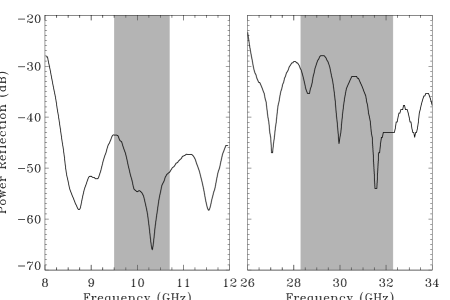
Calibration by an external target corrects reflection and attenuation within the instrument to first order, with the notable exception of the external calibrator reflectivity. Reflections from the calibrator create a systematic offset in the sky-calibrator comparison proportional to the calibrator’s power reflection coefficient and the temperature difference between the calibrator and the sky. During flight, the calibrator will be commanded to different temperatures that could vary from the sky temperature by as much as several K. Achieving 1 mK or better accuracy for the sky temperature thus requires calibrator power reflection below -30 dB.

Figure 2 shows the power reflection coefficient measured for both ARCADE frequency bands using gated time-of-flight techniques at room temperature with the antenna viewing the calibrator in flight configuration (30∘ from normal incidence). The maximum in-band reflection is -43 dB at 10 GHz, with gain-weighted average -49 dB across the band. At 30 GHz the maximum reflection is -28 dB, with gain-weighted average -35 dB. The results do not depend significantly on the orientation of the absorber corrugations to the antenna. Measurements of the antenna/calibrator coupling using a vector network analyzer provide similar limits dB at 30 GHz. As the absorber cools, the epoxy filler shrinks and the conductivity of the iron will increase, increasing the reflectivity and decreasing the absorption. Measurements suggest an increase in power reflection of 30 to 60 percent at cryogenic temperatures Hemmati et al. (1985). Both bands still easily meet the -30 dB requirement.
IV THERMOMETRY
We monitor the calibrator temperature using ruthenium oxide resistance thermometers, chosen for their small size, stability, and large resistance change at cryogenic temperatures. The thermometers consist of commercially available thick-film chip resistors (Dale Electronic RCWP-550) with 76 m Manganin leads providing four-wire resistance measurements. The resistance at room temperature is 10 k, rising to 25 k with slope mK/ at 2.7 K. Five thermometers embedded within the microwave absorber monitor the temperature distribution, while an additional two thermometers mounted next to the heater on the outermost copper plate provide feedback for thermal control. Figure 3 shows the location of the thermometers in the calibrator. Three thermometers (labeled T1, T2, and T3) are embedded near the tips of the Eccosorb corrugations, with two other thermometers (T4 and T5) located in the absorber midway between the bottom of the corrugations and the copper mounting plate. Thermometers T2 and T5 are located atop each other at the center of the calibrator to provide an estimate of vertical gradients within the absorber. After fabrication, the entire calibrator, including the embedded thermometers, was cycled ten times between 300 K and 77 K to relieve thermal stress. A sixth thermometer embedded within the absorber failed open during this initial thermal cycling. The calibrator has since been cooled repeatedly below 2K with no adverse mechanical or electrical effects.

We calibrate the thermometers in situ by immersing the entire calibrator in a liquid helium bath and monitoring the resistance of each thermometer while slowly lowering the pressure above the bath. A NIST-traceable reference thermometer records the bath temperature using the same readout as the calibrator thermometers. Calibrations 4 years apart using two different readout systems agree within the statistical uncertainties ( 0.3 mK). The initial calibration in 1998 used a 1 A excitation current sinusoidally modulated at frequency 1 Hz. A lockin circuit demodulates the voltage drop across each thermometer and integrates for 5.6 seconds to yield the thermometer resistance. The 1998 calibration sequentially measured the 5 embedded thermometers plus the reference bath thermometer. Each thermometer was thus sampled once every 33.4 seconds as the bath temperature fell from 4.2 K to 1.4 K over the course of 10 hours. To prevent bath stratification from producing systematic thermal gradients in the dewar, we use only data taken when the bath temperature was falling fast enough to ensure vigorous boiling. We assume that the bath and calibrator are isothermal and interpolate the measured bath temperature to the time recorded for each calibrator resistance measurement.
We calibrated the thermometers a second time in 2002 using the flight thermometer readout system Fixsen et al. (2002). The 2002 calibration differed from the 1998 calibration in several important aspects. The 2002 calibration used a faster square-wave modulation at 75 Hz, applying power to each thermometer for only 26.7 ms to reduce self-heating, and sampling each thermometer once every 1.067 s. A set of 4 reference resistors monitored any drifts in the readout. Since we used the the same system for ground calibration as flight, effects such as self-heating or the shunt impedance from stray capacitance in the leads are automatically accounted for. The 2002 calibration also included the two control thermometers mounted on the copper heater plate.
We obtained 3 calibration runs in 1998 and 5 more in 2002. Direct comparison between years requires a correction for self-heating. Although self-heating in the 2002 calibration is the same as in flight, it is not the same as the 1998 calibration which applied power to each thermometer for a much longer duration. Additional tests in 1998 measured the change in thermometer temperature as the excitation current varied from 1 A to 10 A at a series of bath temperatures ranging from 1.6 K to 4.2 K. The resulting self-heating is well described by
| (1) |
where mK (varying slightly among the thermometers) and the fitted power law in temperature includes the dependence of both the thermometer resistance and the thermal conductance of the absorber. We correct the 1998 data for self-heating but do not explicitly correct the 2002 data since the effect is included in both the ground and flight readout.
We interpolate the measured resistance data to generate a resistance to temperature calibration for each thermometer over the temperature range 1.4 to 4.2 K. The calibrations derived from each of the 8 individual runs are in good agreement with each other. We quantify this by generating a set of “standard” resistance values spanning the observed range, then converting these to the equivalent temperature using the resistance-temperature calibration curves from each of the 8 separate calibration runs. The resulting scatter in the computed temperatures at each resistance shows the agreement from run to run. Figure 4 shows the 68% confidence uncertainty in the mean for thermometer T1 as a function of bath temperature. Below the superfluid transition all calibrations agree within 0.3 mK, consistent with the noise of the thermometer readout Fixsen et al. (2002). Above the transition temperature the uncertainty increases linearly with the bath temperature. This excess noise is not observed at colder temperatures, suggesting an origin from thermal fluctuations within the liquid helium bath itself.

We use the mean of the 8 individual calibration runs to produce a single resistance–temperature calibration for each thermometer. Observations of the superfluid helium transition at temperature 2.1768 K provide an independent check on the absolute calibration. We record the resistance of each thermometer during each run as the pressure above the bath slowly falls. The superfluid transition produces a distinctive kink in the time-ordered data as the thermal properties of the bath abruptly change. Figure 5 shows all observations of the superfluid transition for thermometer T1 from the 1998 and 2002 calibration runs. The calibrated temperatures correctly reproduce the known transition temperature.
Additional data in 2003 provide thermometer calibration at temperatures from 4.2 to 20 K. This higher temperature calibration placed the calibrator inside a copper cryostat mounted within a liquid helium bucket dewar. We used the flight thermometer readout system to measure the resistance of each flight thermometer as the liquid level in the dewar fell below the calibrator enclosure. The absorber temperature rose from 4.2 K to 20 K over a period of 20 hours, much longer than the few second time constant of the calibrator, ensuring near isothermality across the absorber. Data taken with the absorber immersed in liquid helium agreed with previous measurements from the 1998 and 2002 calibrations.
We conclude that the ARCADE external calibrator meets the requirements for measurements of the CMB blackbody spectrum. The calibrator achieves emissivity greater than 0.9997 within a compact footprint. The calibrator thermometry is stable in time over 4 years, with statistical uncertainty in the temperature calibration of order 2 mK near 2.7 K, limited primarily by thermal fluctuations in the liquid helium bath. Observations of the superfluid transition demonstrate that the absolute temperature scale is accurate within 0.3 mK.
Acknowledgements.
We thank M. DiPirro and D. McHugh of the Cryogenic Fluids Branch at GSFC for supporting the ARCADE thermal calibration. This material is based on work supported by the National Aeronautics and Space Administration under Space Astrophysics and Research Analysis program of the Office of Space Science.References
- Kogut et al. (2004) A. Kogut, E. Wollack, D. Fixsen, M. Limon, P. Mirel, S. Levin, M. Seiffert, and P. Lubin, ApJ (submitted) 00, 00 (2004).
- Hemmati et al. (1985) H. Hemmati, J. Mather, and W. Eichhorn, Rev. Sci. Inst. 24, 4489 (1985).
- Mather et al. (1999) J. Mather, D. Fixsen, R. Shafer, C. Mosier, and D. Wilkinson, Astrophys. J. 512, 511 (1999).
- Gush et al. (1990) H. Gush, M. Halpern, and E. Wishnow, Phys. Rev. Lett. 65, 537 (1990).
- Yokimori (1984) K. Yokimori, Appl. Optics 23, 2303 (1984).
- Fixsen et al. (2002) D. Fixsen, P. Mirel, A. Kogut, and M. Seiffert, Rev. Sci. Inst. 73, 3659 (2002).