Rectangular-Mask Coronagraphs for High-Contrast Imaging
Abstract
We present yet another new family of masks for high-contrast imaging as required for the to-be-built terrestrial planet finder space telescope. The “best” design involves a square entrance pupil having a 4-vane spider, a square image-plane mask containing a plus-sign shaped occulter to block the starlight inside , and a Lyot-plane mask consisting of a rectangular array of rectangular opennings. Using Fraunhofer analysis, we show that the optical system can image a planet times as bright as an on-axis star in four rectangular regions given by .
Since the design involves an image plane mask, pointing error is an issue. We show that the design can tolerate pointing errors of about .
The inclusion of a 4-vane spider in the entrance pupil provides the possibility to build a mirror-only on-axis system thereby greatly reducing the negative effects of polarization.
Each of the masks can be realized as two masks consisting of stripes of opaque material with the stripes oriented at right angles to each other. We call these striped masks barcode masks. We show that it is sufficient for the barcode masks by themselves to provide contrast. This then guarantees that the full system will provide the required contrast.
The rectangular Lyot-plane mask can be viewed as a binary-mask extension of Nisenson’s apodized square aperture concept.
1 Introduction
Following our previous work on pupil-plane masks for high-contrast imaging in the context of terrestrial planet finding (see Kasdin et al. (2003); Vanderbei et al. (2003a, b)), we present in this paper further new pupil masks as well as some pupil-plane/image-plane combinations of masks. Most of our earlier pupil-plane mask designs have an inner working angle (IWA) of , which implies a main mirror in the m range. One of the main objectives leading to the designs presented in this paper was to significantly decrease this inner working angle. If the inner working angle can be reduced to , then the main mirror can be dropped down to the m range and still be capable of studying the same set of stars. This is our goal.
The simplest, but not best, pupil mask presented here achieves a contrast ratio of in four rectangular regions given by . The points of high-contrast that are closest to the center of the star’s image occur along the diagonals and therefore correspond to an inner working angle of (as usual, is wavelength and is aperture).
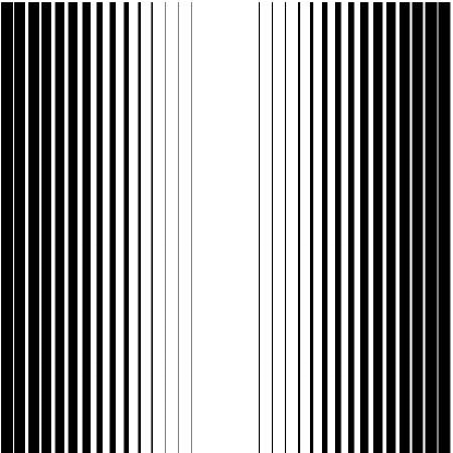
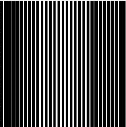
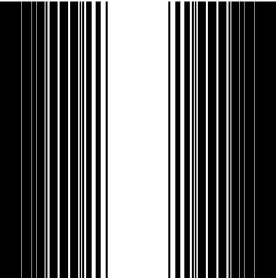
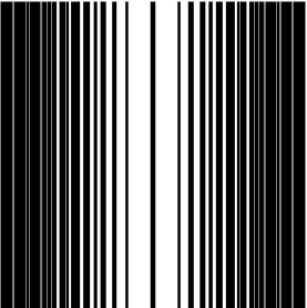
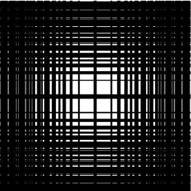
The masks considered in this paper consist of rectangular arrays of rectangular opennings. They can be built as two identical striped masks one placed on top of the other but oriented so that the stripes on one mask are orthogonal to the stripes on the other (see Figure 1). We call the striped masks barcode masks. Each barcode mask need only provide a contrast ratio of —it is then guaranteed that the two-mask overlay will achieve a contrast of . This is important since it is quite feasible to check in a laboratory that a barcode mask achieves but is perhaps impossible to check that a mask achieves in any ground-based laboratory.
Furthermore, we show that one can get an even tighter IWA of by placing a rectangular pupil-plane mask in the Lyot plane of a traditional coronagraph and using an image-plane occulting mask consisting of a “plus-sign” shape, . We show that such a coronagraph can tolerate pointing errors as large as about .
Finally, in the interest of producing an on-axis coronagraph, we present a Lyot-plane rectangular pupil mask which includes a 4-vane spider. A similar spider can then be placed in the entrance pupil and provide the opportunity to place a small secondary mirror at the center of the plane. Having such a spider over the entrance pupil provides the possibility of building an all-mirror on-axis system and in this way greatly reducing the negative effects of differential polarization that plague off-axis designs.
2 Barcode and Rectangular Pupil Masks
In this paper we assume that telescope optics follow the Fraunhofer approximation. Hence, given a pupil plane apodization function , the image-plane electric field is given by the two-dimensional Fourier transform
| (1) |
If the apodization function takes only the values zero and one, then the function represents a mask. If it depends only on one of the coordinates (either or ), then we say that it is a one-dimensional apodization or a one-dimensional mask. We also refer to one-dimensional masks as barcode masks. This family of masks were studied in Kasdin et al. (2004). In this paper, we are interested in masks that correspond to the tensor product of a pair of one-dimensional masks:
| (2) |
The electric field corresponding to a tensor product is itself a tensor product:
| (3) |
In other words,
| (4) |
Tensor products of smooth apodizations were first proposed for terrestrial planet finding in Nisenson and Papaliolios (2001).
Since intensity is the square of the magnitude of the electric field, it follows that for a contrast of , we seek apodization functions that provide the following contrast inequalities:
| (5) |
where denotes the points in the image plane at which high contrast is to be achieved. Suppose as before that the apodization function is a tensor product. If the set is a generalized rectangle
| (6) |
(i.e., ), then the contrast inequalities can be achieved by giving two one-dimensional apodizations that each achieve a contrast ratio of only :
| (7) | |||||
| (8) |
Figure 1 shows a rectangular mask corresponding to . The mask has a open area. Its Airy throughput, defined as
| (9) |
where denotes the inner working angle for the barcode mask, is .
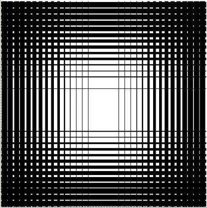
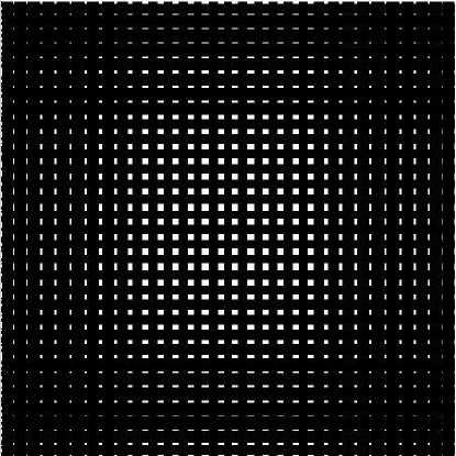
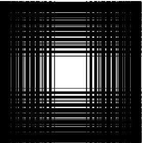
Figure 2 shows another rectangular mask. For this mask, a central obstruction was imposed on the design. With such a central obstruction (and implied spiders) one can hang and hide a small secondary mirror and therefore build a telescope with an on-axis optical path. In this design, we have used . The mask has a open area. Its Airy throughput, is , which is somewhat disappointing. In the Section 4, we present an on-axis design that achieves a much higher throughput.
We end this section by point out that PSFs associated with these masks depend on wavelength only in that the inner working angle is measured in units of , where is wavelength and is aperture. Hence, measured in radians, at longer wavelengths the inner working angle is correspondingly larger.
3 A Lyot Coronagraph
Consider an imaging system consisting of an entrance pupil, a first image plane, a reimaged (Lyot) pupil plane, and a final image plane (containing an imaging device). We assume that each of the first three planes can be apodized/masked. Following Kuchner and Traub (2002), we let denote the mask function for the entrance pupil, the mask function for the first image plane, and the mask function for the Lyot pupil.
The electric field at point in the final image plane corresponding to an off-axis point source is a composition of mask multiplication and Fourier transform:
| (10) |
where denotes the electric field at the entrance pupil corresponding to a point source from direction , denotes a unit mass delta function at , hats denote Fourier transforms and stars denote convolutions.
It is easy to see that if each of , , and are tensor products (, , ), then the electric field again factors into a product of electric fields:
| (11) |
We use this factorization to greatly simplify the coronagraph optimization problems described in the next section.
4 Lyot Coronagraph Optimization Problem and Numerical Results
As in our previous papers (Kasdin et al. (2003); Vanderbei et al. (2003a, b)), we use numerical optimization to maximize some measure of throughput subject to imposed contrast constraints. For the designs presented in this section, we solve the following one-dimensional barcode optimization problem:
| (12) |
The first set of constraints say that is a lower bound on the electric field of a unit off-axis source (i.e, a planet as bright as a star) as the off-axis source varies over the high-contrast region. The second set of constraints say that the magnitude of the electric field at due to an on-axis star is smaller than the electric field at the same point in the image plane due to a much fainter planet whose image is centered at this point . The functions , , and are functions of a single real variable and represent either the or the component of a tensor product that one forms to make the final two dimensional image. By specifying prescribed functions for and (actually, ) we can optimize only the function . In this case, the problem is an infinite dimensional linear programming problem. Discretizing the image and pupil planes reduces the problem to a finite dimensional linear programming problem that can be solved numerically.
We now give two specific examples of Lyot coronagraphs. For the first example, we specify that
| (15) | |||
| (18) | |||
| (21) | |||
| (22) |
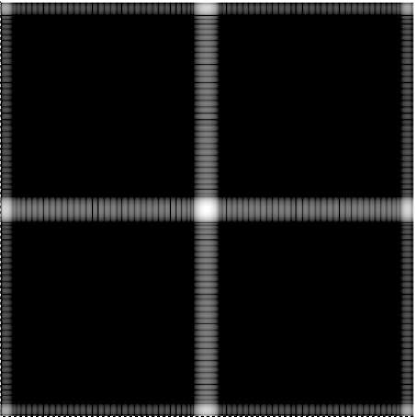
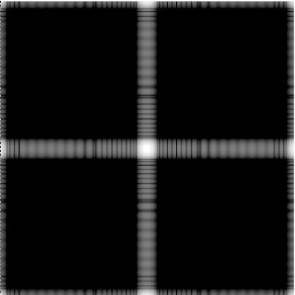
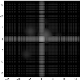
The optimal barcode mask is shown in Figure 3 together with the corresponding rectangular mask.
The second example is the same as the first except that we impose a central obstruction in the pupil-plane masks:
| (25) | |||
| (28) |
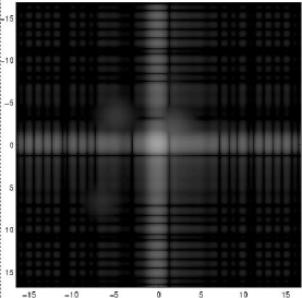
The optimal barcode mask is shown in Figure 4 together with the corresponding rectangular mask.
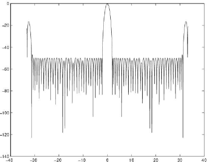
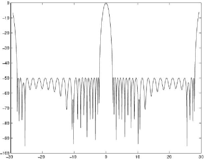
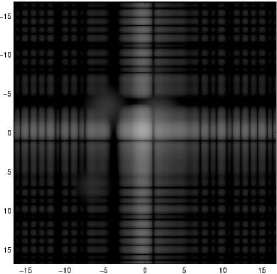
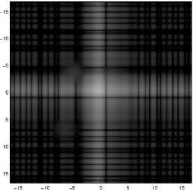
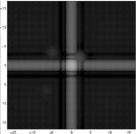
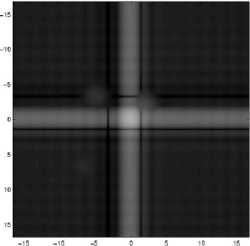
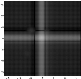
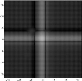
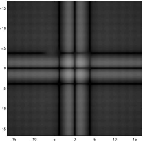
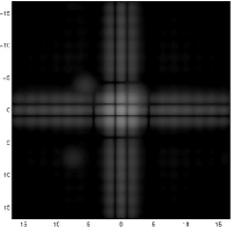
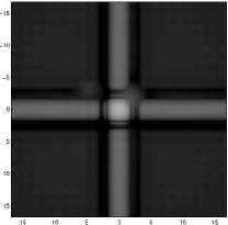
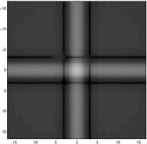
Since the designs presented in this section involve an image plane mask, the associated PSFs depend on wavelength in a more complicated way than the designs given in Section 2. In fact, as Figure 5 shows, the loss of contrast occurs at wavelengths shorter than about and longer than of the design point.
5 Conclusions
In this paper we have presented some new masks for high-contrast imaging. The best design
-
1.
achieves an inner working angle of along the four diagonal directions,
-
2.
includes a four-vane spider so that it can be used in an on-axis telescope design, and
-
3.
consists of two orthogonally oriented barcode masks each one, by itself, being designed to provide only level of contrast.
We include an analysis of the effects of pointing error and chromaticity.
Acknowledgements. We are grateful for the continuing support we have received for this work from NASA and JPL. The first author also wishes to acknowledge support from the NSF (CCR-0098040) and the ONR (N00014-98-1-0036).
References
- Kasdin et al. (2004) N. J. Kasdin, R. J. Vanderbei, M. G. Littman, and D. N. Spergel. Optimal apodizations and shaped pupils for planet finding coronagraphy. in preparation, 2004.
- Kasdin et al. (2003) N.J. Kasdin, R.J. Vanderbei, D.N. Spergel, and M.G. Littman. Extrasolar Planet Finding via Optimal Apodized and Shaped Pupil Coronagraphs. Astrophysical Journal, 582:1147–1161, 2003.
- Kuchner and Traub (2002) M. J. Kuchner and W. A. Traub. A coronagraph with a band-limited mask for finding terrestrial planets. The Astrophysical Journal, (570):900+, 2002.
- Nisenson and Papaliolios (2001) P. Nisenson and C. Papaliolios. Detection of earth-like planets using apodized telescopes. The Astrophysical Journal, 548(2):L201–L205, 2001.
- Vanderbei et al. (2003a) R.J. Vanderbei, D.N. Spergel, and N.J. Kasdin. Spiderweb Masks for High Contrast Imaging. Astrophysical Journal, 590:593–603, 2003a.
- Vanderbei et al. (2003b) R.J. Vanderbei, D.N. Spergel, and N.J. Kasdin. Circularly Symmetric Apodization via Starshaped Masks. Astrophysical Journal, 599:686–694, 2003b.