11email: doberoi@haystack.mit.edu 22institutetext: Laboratoire de Physique et Chimie de l’Environnement, Centre Nationale de la Recherche Scientifique, 3A, Avenue de la Recherche Scientifique, 45071, Orleans Cedex 2, France
22email: jlpincon@cnrs-orleans.fr
A new design for a very low frequency space borne radio interferometer
The non transparency and severe propagation effects of the terrestrial ionosphere make it impossible for Earth based instruments to study the universe at low radio frequencies. An exploration of the low frequency radio window with the resolution and sensitivity essential to meet the scientific objectives will necessarily require a dedicated satellite based interferometer operating at these frequencies. Such missions have been proposed in the literature for about past fifteen years. Today, the steady and impressive advances in technology and computing resources have brought us on the brink of a quantum jump in the performance and capabilities of such missions, increasing their scientific desirability many-fold. This paper presents the concept design which emerged from a study to investigate the feasibility of a low frequency satellite based interferometer operating in the frequency range – titled PrepAration for Radio Interferometry in Space (PARIS). The salient features of the design are: an on-board correlator to reduce the data volumes to be transmitted to the Earth by about two orders of magnitude; use of three orthogonal dipoles in place of two to achieve better polarisation characteristics; direct digitisation of the entire radio frequency band of interest which eliminates the need for a local oscillator system; an overlap in the observing frequency range with upcoming ground based instruments for aid in imaging and calibration and an all-sky imaging capability. The most constraining bottle neck for the present design is the large intra-constellation telemetry requirement. It is expected that technological solutions to meet this requirement will be found in near future as other formation flying missions which share this requirement emerge.
Key Words.:
Telescopes – Instrumentation: interferometers – Techniques: interferometric – Methods: observational1 Introduction
High resolution and high sensitivity low frequency radio astronomy has been a standing challenge till the present time. On the Earth, the non-transparency of the ionosphere below a few MHz and its severe propagation effects below few tens of MHz have prevented detailed studies of the radio universe at these frequencies. The 60s and 70s saw some attempts to investigate the electromagnetic spectrum below 30 using space borne radio astronomy experiments on-board individual satellites (Alexander,, 1971, and references therein). The last explorations in this series were conducted by the two Radio Astronomy Explorer missions (RAE) in the late 1960s and early 1970s (Herman et al.,, 1973; Alexander et al.,, 1975). These missions were dedicated radio astronomy missions and covered the frequency ranges – and – , respectively and had practically identical instrumentation. RAE-1 was placed in a , circular, inclination, retrograde orbit around the Earth and RAE-2 in circular Lunar orbit at and inclination. These satellites provided resolutions of about at and at . Even today, it is not possible to achieve significantly better resolution using individual spacecraft.
A space based interferometer will be essential to conduct a detailed study of the radio universe below few tens of . In this paper, we refer to the frequency range below as the Very Low Frequency (VLF) range. The subject has been discussed in the literature for about fifteen years now. Weiler et al., (1988) proposed a four satellite mission with crossed travelling wave V-antennas, similar to the ones used on the RAE satellites. Four discreet bands of each were to be covered in the range – . Basart et al., (1997) suggested a strategic plan for a space based low frequency array progressing from spectral analysis on-board a single spacecraft to a two element interferometer in Earth orbit, continuing to an interferometer array in Earth or Lunar orbit, culminating in Lunar nearside and far-side arrays. They considered it necessary to have high gain antennas and suggested the use of spherical inflatable arrays with a large number of active elements as interferometer elements for the space array. Jones et al., (2000) were the first to consider short dipoles to be suitable elements for space interferometer. They proposed a 16 element array on a distant retrograde orbit, covering – with up to bandwidths of observation. These studies focused on achieving the best possible performance using the technology available to them.
The enormous advances in technology and the vast increase in the computing resources available have brought it within reach to tailor the solutions to the specific needs of VLF radio astronomy and made it possible to plan the next generation of radio interferometers. This is amply reflected in the many new projects which are being actively pursued, for instance the Low Frequency Interferometer (LOFAR), Square Kilometer Array (SKA), Alan Telescope Array (ATA) and the Frequency Agile Solar Telescope (FASR). This work is an attempt to present the next generation of design for space based VLF interferometers. An important guiding principle for the study was to come up with a design tailored to the specific needs to VLF interferometry. A design motivated by how one would like an ideal instrument to be, and not one which can necessarily be realised in immediate future. The limitations imposed by the currently available technology were hence not regarded as hard constraints. We have, however, exercised caution, in our endeavours to think beyond the current technological limitations, to not wander off far away from the realm of the feasible. The design presented is rather aggressive in the aspects of technology which are progressing most rapidly and practically respects the existing constraints from technologies which are progressing at a slow pace. Judging from present trends, it is expected to become feasible in near future. The study, titled PrepAration for Radio Interferometry in Space (PARIS), was a collaborative effort between the Laboratoire de Physique et Chimie de l’Environnement, the Laboratoire d’Etudes Spatiales et d’Instrumentation en Astrophysique from the Paris-Meudon Observatory and the Nançay radio astronomy station.
The next section briefly summarises the scientific motivation behind a VLF space interferometer. The third section details the aspects of VLF sky and interferometry technique which were regarded as the major design drivers for this study. The concept design is presented in the fourth section and the fifth highlights some key aspects of the data analysis strategy. Calibration and formation flying issues are discussed in the sixth section and the seventh section presents the conclusions.
2 Scientific objectives
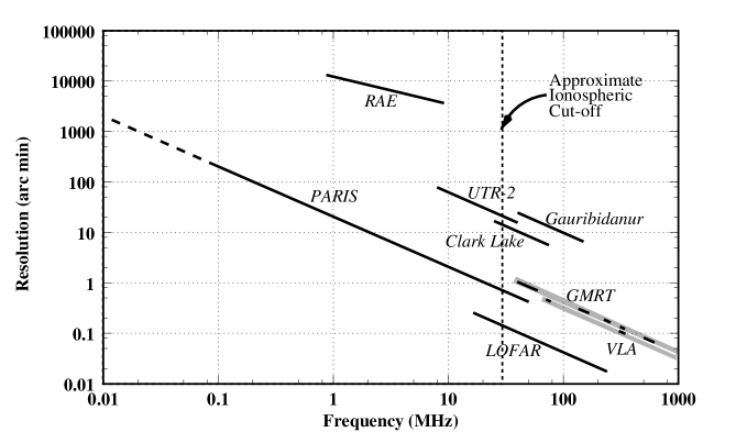
Far from showing a simple extension of the more energetic phenomena seen at higher frequencies, studies at very low radio frequencies promise new insights in astrophysics and solar physics. The main objective of PARIS is to produce the first ever sensitive high resolution radio images of the entire sky in the frequency range from to . Only a space borne radio interferometer, free from the corruptions due to the ionosphere and away from the terrestrial radio frequency interference, can deliver the sensitivity and the dynamic range necessary for useful astronomy in this frequency range. Fig. 1 clearly shows that PARIS will open up a new window of opportunity in the last unexplored part of the electromagnetic spectrum.
The topics discussed in this section highlight only some of the major scientific objectives and potentials of the mission. For a more detailed review the reader is referred to the following dedicated publications: Radio Astronomy from Space by Weiler, (1987); Low Frequency Astrophysics from Space by Kassim and Weiler, (1990); Radio Astronomy at Long Wavelengths by Stone et al., (2000).
2.1 Very low frequency astrophysics
The astrophysics issues addressed by a VLF space borne radio interferometer include studies of discreet extra-galactic, galactic and solar system objects to studies, the diffuse emission of galactic origin and those of the intervening Interstellar Medium (ISM). The most prominent among these are:
-
1.
The determination of very low frequency spectra – The measurement of the low frequency radio spectral behaviour is important for improving our understanding of the prevailing physical conditions and emission and absorption process at work (Erickson,, 2000). Many physical processes involved in emission and absorption of radiation are observable only at very low radio frequencies.
-
2.
Evolution of Galaxies – A low frequency space interferometer will be particularly sensitive to the radio emission from low energy electrons which have long radiative lifetimes. These old electrons form an excellent probe for studying the history of radio sources and will allow one to detect the fossil radio plasma whose signatures at higher frequencies are much fainter (Enßlin and Gopal-Krishna,, 2001; Reynolds and Begelman,, 1997). These electrons allow one to detect the early epochs of activity of radio galaxies, trace their evolution in time and will help constraint the models of galactic evolution and of super-massive black holes in the galactic nuclei.
-
3.
The study of the exchange of matter and energy between stars and the interstellar medium – Within our Galaxy, the interferometer will observe the background Galactic synchrotron emission and the extragalactic objects overlaid with a complex absorption pattern generated by the diffuse ISM and the discreet objects like supernova remnants. Absorption from dense clumps of ionized hydrogen and the warm diffuse component of the ionized ISM will be detectable (Dwarakanath,, 2000; Reynolds,, 1990). Multi-frequency all sky maps will allow one to do a tomographic study of the distribution of ionized hydrogen. This will be a considerable new source of information for improving the existing model for galactic distribution of free electrons like the one by Cordes and Lazio, (2002). These maps will also help in determining the origin of the energy content of the ionized hydrogen. In addition to revealing the large-scale structure of the ionized ISM, it may also be possible to probe the small scale turbulence, by examining the propagation effects like an apparent increase in angular size and fluctuation in dispersion measure measurements towards pulsars (Cordes,, 2000). This will help in our understanding of the injection and turbulent dissipation of energy within the ISM. By imaging the synchrotron emission from the electrons in the shock regions such a mission will allow to test the theory that cosmic rays are accelerated in supernova remnants shocks (Duric,, 2000).
-
4.
The discovery of new phenomena – An interferometer in this frequency range will provide a two order of magnitude improvement in both sensitivity and resolution, when compared to the existing observations from individual spacecraft. As with any first exploration of a part of the electromagnetic spectrum, this mission is justifiably expected to discover objects and phenomena not seen at higher frequencies.
2.2 Solar and Space physics
PARIS will produce the first ever interferometric very low frequency radio images of the solar corona, solar transients like the coronal mass ejections (CMEs) and the shock-fronts associated with consequent interplanetary disturbances (IPDs). The key issues in solar/space physics to be addressed by a space borne VLF radio interferometer are:
-
1.
Imaging of solar transients and studying their evolution – Solar transient phenomena such as solar flares, filament eruptions and CMEs are manifested by distinct types of non-thermal radio emission. The study of the spatial and temporal evolution of this emission is essential to a better understanding of the Sun-Earth connection. The proposed mission will allow us to image and track these solar induced disturbances, particularly the CMEs, from the vicinity of the Sun all the way to 1 AU. This requires observing frequencies from tens of to tens of and hence these measurements can only be made from space. The existing low frequency observations of the Sun are all made using individual spacecraft. Their strength lies in their ability to provide wide bandwidth and high spectral and temporal resolution dynamic spectra, but this data cannot provide radio images. A high resolution wide band imaging instrument with continuous spectral coverage will provide information of the morphology and spatial distribution of emission and will be a fitting compliment to the dynamic spectrum studies (Dulk,, 2000; Gopalswamy,, 2000). Images of transient radio bursts are also of prime important for space weather forecasting applications. It is, perhaps, worth noting that the STEREO mission, scheduled for launch in late 2005, will track the centroids of radio emission and shed some light on the emission pattern of the emission but will not have true imaging capabilities.
-
2.
Mapping of large scale interplanetary magnetic field topology and interplanetary density structures – The mission will also provide the means for remote sensing of the coronal and interplanetary density and magnetic field structures in the inner heliosphere. For instance the electron beams producing type III bursts follow magnetic field lines outward from their source in the corona. Imaging and tracking these bursts will reveal the topology of interplanetary magnetic field lines.
-
3.
Improving our understanding of emission mechanisms and particle acceleration – The extended dynamic range of such an instrument will make it possible to image both thermal and non-thermal sources simultaneously. Very low frequency images of thermal emission will, for the first time, provide information on coronal holes, streamers and CME structures at heliocentric distances larger than 2 solar radii. This information will form a natural complement to and will extend the maps of these structures obtained by white light and X ray imaging. Images of shock-fronts and bursts associated with solar energetic particle (SEP) events will help improve our understanding of particle acceleration sites and mechanisms (MacDowall et al.,, 2003).
3 VLF interferometry
Though all interferometers share the same mathematical foundations, their practical implementations change considerably with the frequency range of interest. Every few orders of magnitude in wavelength, the problem of designing an interferometer changes in character and essentially evolves into a different problem with new and different aspects becoming the design drivers. For instance, the detailed designs of an optical interferometer and a high frequency radio interferometer do not have much in common, even though they implement the same functional blocks. The VLF range (say – ) differs from the usual domain of radio astronomy (say – ) by three orders of magnitude. It is reasonable to expect the design considerations for a VLF interferometer to differ from those for interferometers at much higher radio frequencies. Some of these considerations stem from natural causes and others due to from technological aspects. In this section we identify the key aspects of VLF interferometry which were considered to be the major design drivers.
3.1 The VLF sky
The most conspicuous feature of the VLF sky is the enormously strong Galactic background radiation. Fig. XX shows both the brightness temperature and the specific intensity in the frequency range of interest. The specific intensity

of polar galactic background is at , peaks at a value of close to and slowly reduces to by . The brightness temperature is in excess of by , comes close to at and continues to rise more slowly to at . To put things in perspective, the polar galactic background brightness temperature at is (Haslam et al.,, 1982) and reduces to at (Platania et al.,, 1998).
3.2 Large field of view
The directivity, or field of view (FoV), of a receptor for electromagnetic waves is characterised by , where is the wavelength of observation and the dimensions of the receptor. The Very Large Array (VLA), one of the most successful radio interferometers, has antennas of 25 meter diameter and is most often used to observe in a wavelength range from to ( – ). Measured in units of , the diameter of the antennas ranges from at the low frequency end to at the high end, leading to FoVs smaller than a hundredth to a thousandth of a radian across. In the VLF band the ranges from at to at . The large wavelengths and the necessity to deploy the structure in space preclude the possibility of limiting the field of view of the receptors by using apertures many in size, at least in the near future. The receptor size is expected to be smaller than the wavelength of operation for practically the entire frequency range. The FoV of individual receptors is hence expected to be very large.
The intense galactic background and the very large FoV imply that unlike at high frequencies where the , the equivalent noise temperature corresponding to the sum of all the contributions to the signal received at the output of an interferometer element, is dominated by , the noise contribution of the receiver electronics, at VLF frequencies, will necessarily be very large and will be dominated by the contribution of the galactic background (Fig. 2).
3.3 Three dimensional sampling
The aim of interferometric imaging is to arrive at the Brightness distribution in the sky at an observing frequency , , from the measured visibilities, . For a phase tracking interferometer with a small fractional bandwidth (), the two are related by the following expression which gives the response to spatially incoherent radiation from the far field
| (1) |
where , and are the orthogonal components of the baselines. They are measured in units of and forming a right handed coordinate system such that and are measured in a plane perpendicular to the direction of the phase center, pointing to the local East and to the local North. and are direction cosines measured with respect to the -- coordinate system and is the antenna beam pattern. If the third term in the exponential can be ignored, then equation 1 reduces to an exact 2D Fourier transform relationship (Perley,, 1999). This can usually be achieved by limiting the FoV of the antenna primary beam to a narrow enough angular region, by building a large enough aperture. This is referred to as the small FoV approximation and most of the existing interferometers operate in this regime. Due to the large FoVs in the VLF regime, we will be well outside this regime and hence the full 3D formalism will need to be employed for the inversion of visibility data.
For most synthesis imaging instrument in operation, due to the distribution of the antennas on a near planar surface and small FOVs, it usually suffices to decompose the baseline vectors into the u and the v components. For a space borne VLF interferometer with a 3D distribution of elements and very large FoVs, it will be necessary to decompose the baselines along , and axes. Analogous to conventional ground based synthesis imaging, where the fidelity of the final image depends upon the completeness of the sampling of the - plane, for a VLF space array it will depend upon the completeness with which the -- volume is sampled. The constellation configuration chosen for a VLF interferometer must therefore try to achieve a good sampling of the 3D -- volume, as opposed to the 2D - plane as for most other aperture synthesis interferometers.
3.4 Mapping the entire field of view
The Eq. 1 in the previous section, truly holds only for a monochromatic interferometer. All practical instruments measure visibilities over a finite bandwidth, , centered at some frequency, and, the data within are treated as if they were at . This imprecision in handling the data leads to a gradual decrease in coherence of the signal measured at two elements with increase in , the distance of the source from the phase center, and the baseline length. For a point source, the effect of fractional bandwidth and baseline length on the reduction in peak response (, where is the peak response) can be conveniently parameterised in terms of a dimension parameter defined as , where is the distance of the point source from the phase center measured in units of the half power beam widths for a given baseline (, where is the wavelength corresponding to and is the length of the baseline) (Bridle and Schwab,, 1999). Substituting for , can be expressed as . When the peak response decreases to and further reduces to when . A necessary requirement for synthesis imaging is that all the measured visibilities used to reconstruct the sky brightness distribution receive coherent emission from the same physical patch of the sky.
Typically, interferometer baselines span a wide range while the bandwidths over which individual visibilities are measured is a constant. This leads to visibilities from different baselines receiving correlated emission from sky patches centered at a common spot but differing in size. At high radio frequencies this poses no problems because the FoV gets limited by the diffraction beam of the aperture before the effects of the coherence in the radiation received at different elements reduced significantly. On the other hand, at VLF frequencies, as discussed in the preceding sections, the FoV of the receptors is necessarily very large. A reasonable solution to the problem of matching the patches from where correlated emission is received is to measure visibilities over sufficiently narrow bandwidths so that even the longest baseline receives correlated flux from the entire FoV.
At high frequencies, for most part the background emission is so weak that sky can be regarded as cold and the number density of radio sources is such that the sky can be considered to be largely empty. Hence, the common practice of not imaging the entire FoV but only a small parts of it from where the emission is expected is not only acceptable but also prudent. At VLF frequencies, the sky background is extremely intense. This implies that in order to obtain the best image fidelity and dynamic range performance, it would be necessary to image the entire region from which correlated flux is received, which, in the present case corresponds to the entire FoV.
Mapping a large primary beam also requires caution to be exercised on another front. The geometric delay, , suffered by signal arriving from different directions changes widely, from perpendicular to baseline to along the baseline. The process of cross correlation, however, allows for correction of only a unique geometric delay, . If the residual geometric delay, , exceeds for some directions, where is the coherence time of a band limited signal of bandwidth , the signal received from these directions will loose correlation. This effectively limits the field of view which can be mapped by the interferometer. Such a situation can be avoided by correlating the signal over sufficiently narrow channel widths so that the inequality mentioned above is never satisfied. As an example, a baseline length of a requires that the channel width be .
3.5 Telemetry considerations
The telemetry bandwidth available to the VLF interferometer to transmit the data to the Earth is an important design driver. We estimate the largest telemetry bandwidths expected to be available to a VLF interferometer in near future to lie in the range to (Mega bits per second). This is based largely on the fact that the ALFA study (Jones et al.,, 2000) expected to sustained a telemetry bandwidth from an array of spacecraft located from the Earth, using the existing subnet of NASA Deep Space Network (DSN) facility.
All the earlier proposals for space based VLF interferometers chose to transmit the Nyquist sampled time series from every receiver on each of the satellites to the Earth. This classical approach offers the advantages of simpler satellite architectures and a homogeneous array which provides ample redundancy. The principal disadvantage however is that because of the very voluminous nature of the data, these designs can only provide a rather limited observation bandwidths. The ALFA proposal, for instance, provided a maximum of , using a telemetry down-link and a quantisation for the data stream (Jones et al.,, 2000).
In order to preserve the expected dynamic range of about in the input signal (Bougeret,, 1996), a bit sampling is required. This large number of bits required per sample further reduce the available bandwidth of observation by close to an order of magnitude. There is no doubt that a larger bandwidth of observation than what the classical approach can provide in near future would be very desirable. There are only two ways in which this can be achieved, either by simply waiting for the telemetry technology to progress sufficiently to meet the needs of VLF interferometry or by doing some on-board data processing to reduce the data volumes. For an interferometer, the data products which can be meaningfully averaged, are the visibilities. For most ground based instruments the process of computing visibilities is performed by dedicated custom made hardware of significant complexity. The hardware capabilities required for on-board computation of visibilities have remained significantly beyond the state of the art till recently. Therefore, in spite of the low bandwidth disadvantage, transmitting the Nyquist sampled time series had been the only feasible option for the earlier VLF space interferometer designs.
Judging from the current trends in the industry, the computational capabilities of space qualified hardware are expected to increase at a rate considerably larger than at which the telemetry bandwidths are expected to grow. We, therefore, consider it judicious to assess the option of on-board visibility computation and subsequent time and frequency averaging to reduce the data volume and increase the available bandwidth of observation.
3.6 Propagation effects
At the VLF frequencies, the inhomogeneous, turbulent and magnetised plasma of ISM and interplanetary medium (IPM) act like mediums with refractive index fluctuating in both space and time. The propagation of the VLF radiation from distant radio objects through this medium modifies the incident wavefronts in a considerable manner. The implications of most relevant of these propagation effects are enumerated.
-
1.
Angular broadening – The passage of VLF radiation through ISM and IPM results in significant apparent angular broadening of compact sources (Rickett and Coles,, 2000). This angular broadening effectively imposes a limit on the finest resolution with which one can expect to study the universe, irrespective of the baseline lengths involved. The angular broadening scales as the square of the wavelength of the radiation and is hence most severe at the VLF range. Fig. 3 shows the angular broadening of a point source due to IPM and ISM as function of frequency. The resolution afforded by baselines of – is also shown to provide a point of reference.
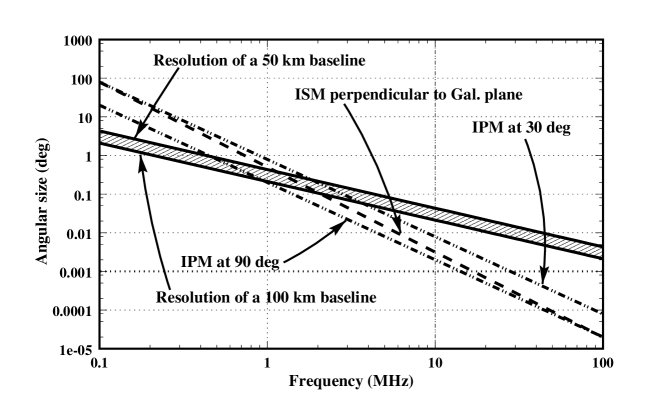
Figure 3: Angular broadening due to ISM and IPM – The dashed line shows the angular broadening of a point source due to the ISM in a direction perpendicular to the Galactic Plane. The effect in the Galactic place can be two to three orders of magnitude larger. The dashed-dotted lines show the angular broadening of a point source due to the IPM at elongations of and respectively. The shaded region is bounded by the resolution of baselines of length and . -
2.
Temporal broadening – The scattered rays which lead to angular broadening of compact sources travel through different paths to the observer. This leads to a spread in the travel time of signal, which results in smearing of transient signals like pulses from a pulsar. Due to the comparatively much larger distances involved, interstellar temporal broadening is much more severe ( at ) than interplanetary ( at ) (Woan,, 2000).
-
3.
Depolarisation of radiation – The magnetised nature of the ISM and the IPM, their large inhomogeneities combined with the fact that magnitude of Faraday rotation is proportional to conspire to make this an important effect for VLF range. The multi-path propagation from source to observer, with possibly a different Faraday rotation for each path, presents a fundamental limitation to the detection of linearly polarised signal. Unlike the case at higher frequencies, this cannot be treated like simple foreground Faraday rotation which can be estimated by multi-frequency measurements. Circular polariastion, however, is not effected by Faraday rotation though the intrinsic luminosity of cyclotron processes which produce it is much lower than that of synchrotron processes. A detailed discussion on polarisation effects can be found in Linfield, (1996).
-
4.
Absorption effects – The free-free absorption is expected to render the ionised ISM optically thick at some turnover frequency. This frequency will be a function of both, the emission measure of the medium and its electron temperature. The Warm Ionized Medium is expected to turn optically thick for path lengths of about at . As the Galactic disc is about in thickness, the sky will appear to be foggy in all directions at frequencies of a few MHz. It will be possible to see out of the Galactic plane at higher frequencies and the apparent appearance of the plane itself will be dominated by the mottling due to the presence of discreet regions of high electron density. The subject is discussed in considerable detail by Dwarakanath, (2000).
-
5.
Reflection, refraction and scattering close to the Sun – Due to the large gradient in the electron density in high Solar corona, a variety of unusual reflection and refraction phenomenon take place in this region. An increasingly large fraction of the Solar corona becomes inaccessible to the radio waves at frequencies below as ray paths get reflected back into the IPM. Bracewell and Preston, (1956) give an in depth discussion of this and a few other interesting phenomenon. Close to the Sun, there is considerable evidence, from multi-spacecraft studies of solar bursts below , for the existence of anomalous beaming and large angular scattering (Lecacheux et al.,, 1989).
We note that of the effects mentioned here, only scatter broadening effects impact the design of a VLF interferometer, all the others limit the science which can be done at these frequencies independent of the design details.
3.7 The radio frequency environment
A look at the frequency allocations chart for the United States of America shows that the entire VLF band from onwards is allocated to specific users, with the exception of – and – which are reserved for radio astronomy. The spectral allocation situation is expected to be similar in other parts of the world. Erickson, (1990) concluded in his study that the radio frequency interference (RFI) in near the near Earth environment was too strong to allow sensitive VLF interferometric observations. Measurements from the WIND satellite, located from the Earth, in the frequency range - reveal that in spite of the geometric dilution and the attenuation offered by the ionosphere, RFI is often stronger than the Galactic background emission (Kaiser et al.,, 1996). A strong correlation between the spectral bands allocated to commercial shortwave stations and the RFI affected parts of the spectrum was found. However the wide spectral channels of on-board instrumentation did not provide sufficient resolution to routinely identify individual broadcast services, which are a few wide and spaced about apart. It was also evident that commercial shortwave transmission does not account for all the observed RFI. Given the grossly insufficient coverage provided by the protected bands, a VLF radio interferometer will inevitably have to operate in a rather unfriendly RFI environment. It will hence be necessary to develop a RFI mitigating strategy.
3.8 Non-stationarity of the sky
Often, the instantaneous sampling of the u-v plane achieved by an interferometric array falls short of the requirements for a good image of the desired part of the sky and does not provide sufficient sensitivity. Ground based instruments rely on rotation of the Earth to improve the u-v coverage and observing for longer durations improves the sensitivity. The space borne VLF interferometer will similarly rely on the motion along its orbit and changes in baselines due to relative velocities between the constellation elements to improve its sampling of the u-v-w volume and the sensitivity. Using visibilities collected over a period of time to construct a single map of the sky implicitly assumes time stationarity of the sky over the period of observation. On the time scales of operation of the VLF interferometer mission, the evolution of most astronomical sources is a non issue and we may choose to ignore the low frequency variability, weather intrinsic or introduced by the propagation effects. However, the apparent positions of the solar system objects, with respect to the more distant objects, change rapidly. The position of the Sun, for instance, changes by about per day. This implies that the sky sampled by the interferometer at different epochs corresponds to different realisations of the sky, differing in the location of the solar system objects with respect to the more distant ones. The active Sun, Earth and Jupiter are among the stronger discreet sources in the VLF range and their emissions have an elaborate frequency-time structure. In addition, the apparent angular sizes of sources will vary in time, as their angular distance from the Sun changes (Sec. 3.6, Fig. 3).
4 The design concept
In order to keep the mission economically feasible a micro-satellite based approach has been chosen so that all the interferometer elements can be deployed using a single launch vehicle. The interferometer is envisaged to comprise of a constellation of about free floating three axis stabilised micro-satellites. Each member of the constellation will serve as an interferometer element. As motivated in section 3.5 we investigate the possibility of an on-board correlator. This has the consequence that not all the spacecraft will be identical. One of them will receive the data streams from all the others and will perform on-board Digital Signal Processing (DSP) to reduce the data volumes to be transmitted to the Earth. We refer to this spacecraft as the Mother spacecraft. In order to avoid a single point of failure in the design, it will be necessary to equip a few of the satellites, say three, to take up the role of the Mother spacecraft. Some details of a design based on this concept follow along with brief justifications of the choices made.
4.1 Frequency coverage
The mission has been designed to cover the frequency range [ – ]. The frequency range, useful for radio astronomy, is limited on the lower end by the plasma frequency of the IPM, known to be about a few tens of at . Close to the plasma frequency, interferometric measurements are so badly corrupted by the propagation effects that they no longer remain useful for studying distant radio sources. It may be possible to conduct meaningful interferometric observations down to . At the high frequency end, we expect that by about , it will be scientifically more rewarding and much more economical to use the more powerful and versatile upcoming ground based low frequency instruments like LOFAR. None the less, we strongly advocate an overlap in the frequency ranges covered by the space array and the ground based instruments and suggest as the upper frequency limit for the space array (Fig. 1). The overlap in frequency range will help in calibration and allow the space array to benefit from the information of the sky obtained by the ground based array. A reliable and detailed model for the low frequency sky obtained by the ground based instruments will provide a very good anchor point from where to boot strap to proceed to lower frequencies. We note that the instrument itself will be designed to work below the plasma frequency of the IPM and the measurements in this part of the spectrum can serve as local plasma measurements which can be used to serve different scientific objectives. Their discussion lies beyond the scope of this paper.
4.2 Receiving elements
As mentioned in section 3.2, for a VLF interferometer, the long wavelengths involved, the constraints of a space borne mission and a micro-satellite based architecture limit the choice of elements to short dipole antennas. Due to their poor noise characteristics, short dipoles are usually not the preferred choice for receiving elements in radio astronomy. However, the intense Galactic background emission in the VLF range and the enormously wide primary beam of the short dipole ensure that the the noise on the measured signal is dominated by that due to the Galactic background emission and not the receiver noise (Manning,, 2000). The dipoles could be based on the monopole stacer design used for the WAVES instrument on board the WIND satellite (Bougeret et al.,, 1995) or the ones designed for SWAVES on board STEREO. These antennas are in length and the noise contribution of the antenna itself is less than that from the Galactic background in a frequency range from to providing a good match to the needs of a VLF interferometer. The choice of the interferometer element specifies the FoV or the primary beam size for the interferometer and for a short dipole it is , or about . Each satellite will be equipped with three mutually orthogonal short dipoles, in order to record all the information in the electromagnetic field incident on the satellite.
The use of three mutually orthogonal dipoles offers some advantages over the conventional use of two mutually orthogonal ones – computing all the nine () cross-correlations per baseline allows one to construct Stokes parameters to characterise the polarisation of radiation received from any arbitrary direction (Carozzi et al.,, 2000), as opposed to being limited to directions close to the perpendicular to plane defined by the two dipoles; on being equipped with the additional ability to compute all the nine auto-correlations, the use of three orthogonal dipoles permits individual satellites to be used for direction finding of polarised sources (Ladreiter et al.,, 1995), a potentially useful feature for initial deployment of the constellation and for calibration; and lastly the use of independent data from a third dipole can be considered as an increase in the effective collecting area or an effective reduction in observation time needed to achieve a given sensitivity.
4.3 The signal path and on-board Digital Signal Processing
The signal from each of the three short dipoles on every constellation elements is fed via a low noise amplifier to an analog to digital converter (ADC). The ADC Nyquist samples the signal at to cover the entire radio frequency (RF) range of interest. The input signal must be sampled with sufficient bit depth to to preserve its fidelity. Bougeret, (1996) suggested that, for a short dipole, the dynamic range of the input signal is expected to be to . We aim for a dynamic range, which requires sampling using effective bits.
The primary guiding principle for on-board Digital Signal Processing (DSP) approach is to distribute it to the largest extent possible, in order to avoid a build up of DSP requirements at some later stage in the signal chain. The three digitised time series on each of the spacecrafts will be Fourier transformed in real time. The spectral width of the frequency channels is determined by the length of the longest baseline and the requirement of imaging the entire primary beam (Sec. 3.4). A maximum baseline of (Sec. 3.6) and a requirement that the reduction in peak response due to decorrelation loss be less than (; Sec. 3.4) for near fields of view, lead to a bandwidth of for the width of the spectral channels.
The DSP required to achieve this spectral resolution will be implemented as a two stage fast Fourier transform (FFT) engine. As an illustration, the first stage takes a point real transform and yields and point complex spectra with a spectral resolution of . A second stage will perform a 128 point complex Fourier transform on a subset of these spectral channels leading to wide spectral channels. Performing the second stage FFT on of the spectral channels delivered by the first stage of FFT leads to a requirement of (complex multiplications and additions per second) per polarisation per satellite, for a sampling. The number of channels on which the second stage FFT will be performed will depend on computing power available on-board and the intra constellation telemetry bandwidth limitations. A selected subset of these narrow spectral channels will be re-sampled using one or two bits and transmitted to the Mother spacecraft.
The Mother satellite will receive the Nyquist sampled spectral data from all the constellation members and will compute the auto and cross correlations. The resulting visibilities will be averaged over suitable intervals in frequency and time. Say of the available spectral channels are resampled using one or two bits and transmitted to the Mother satellite. This leads to a requirement of for the computation of a set of 9 () cross and self correlations for each baseline. Keeping in mind that the operations on the individual constellation members are done on data and most of those on the Mother satellite are done on - data, the total on-board computing requirements for the Mother satellite will be about twice as much as those for other constellation members for the RF bandwidth provided by the above design. The correlator itself will be a flexible and reconfigurable device. It will allow a range of combinations of spectral and temporal resolutions and the number of baselines for which the correlations are computed, while keeping the total throughput from the correlator a constant and respecting the constraint of available telemetry bandwidth to the Earth. For instance, it will be possible to get higher temporal and/or spectral resolution at the cost of decreasing the bandwidth of observation and/or number of baselines used. It will be desirable for the correlator to have the ability to respond to self generated and external triggers in order to switch to an appropriate temporal and spectral resolution mode in response to an event. The averaged visibilities will finally be transmitted to the Earth, where the rest of the analysis will take place. The temporal extent over which the visibilities can be averaged will be decided by the shorter of the time scales at which it is desired to study the received emission and the relative velocities of the constellation members which lead to a gradual change in baselines. The spectral averaging extent will depend on the requirement for spectral resolution and the intrinsic spectral characteristics of emission.
At first sight, the tasks of digitising a 40 MHz wide band and Fourier transforming it into wide spectral channels seems like an unlikely task for a micro-satellite. The present day technology, however, comes very close to meeting these requirements. According to its data sheet, the best performing space qualified ADC from Analog Devices available in July 2003, AD9042, can sustain a maximum sampling rate of , has a typical power dissipation of and provides a spurious free dynamic range of over . It seems likely that by the time it is required, the available technology will allow the signal to be oversampled in order to recover some of the losses in digitisation process. Space qualified FPGAs with gates are already available from Xilinx and their road map for the near term future promises Virtex-II Pro family devices with gates by the end of 2004. For the example configuration discussed here, just one of these devices per spacecraft will comfortably be able to handle the DSP requirements for all three dipoles. Preliminary studies indicate that it may even be possible to accommodate the additional computing requirements of the Mother spacecraft on the same device or may at most require the use of another similar device. Meeting the on-board DSP requirements of a VLF interferometer in near future does not seem to pose a significant problem.
4.4 Telemetry and bandwidth of observation
The telemetry issues can be sub divided into those relating to intra constellation telemetry and telemetry from the Mother spacecraft to the Earth. We first discuss the former. As mentioned in section 3.5, the limitation on the telemetry bandwidth to the Earth led us to consider the approach of reducing data volume on-board. However, it is impossible to reduce the data rates to below Nyquist requirements before the computation of visibilities. As a consequence, all constellation members transmit Nyquist rate data streams to the Mother spacecraft. It is instructive to compute this number per of RF bandwidth. For each constellation member transmitting data to the Mother spacecraft, this amounts to , with a , the number of dipoles per spacecraft, of 3 and , the number of bits per sample, of 1. For a constellation of spacecrafts, the Mother spacecraft receives data from spacecrafts simultaneously. For the 16 element constellation under consideration, this implies a rate of . The telemetry rate grows by an order of magnitude to accommodate the RF bandwidth which the on-board DSP can comfortably deliver. This design, therefore, has intra constellation telemetry requirements in the range of – .
The telemetry requirements for transmission of data from the Mother satellite to the Earth depend on the spectral and temporal averaging performed on-board. The amount of data to be transmitted to the Earth per second is given by the following expression
| (2) |
where the first term gives the number of baselines for a constellation comprising of spacecrafts, is the number of correlations computed for each baseline, is the number of bits used to represent each complex visibility, is the RF bandwidth for which visibilities are computed, is the width of each of the spectral channels, is the integration time and the number of spectral channels which are averaged over. For a of , using a of 16, of 9, of 16, of and averaging over spectral channels for seconds leads to a data rate of . For a RF bandwidth, it grows to a modest and the entire RF bandwidth accessible to the instrument, , requires only . The vast reduction is data volume achieved by on-board data processing is apparent on comparing the rates at which flow in and out of the the Mother spacecraft or by recalling that the ALFA design required of telemetry for a RF bandwidth of . The huge reduction of telemetry requirements to the Earth offers another benefit as well. The fact that the data rate from earlier mission designs were was essentially limited by available telemetry implied that the observations could be made only for the duration of the telemetry down-link, requiring a 24 hour down-link for continuous observations. With the large reduction in the telemetry requirements, it might now become possible to reduce the down-link duty cycle without compromising the observing duration.
The RF bandwidth over which the visibilities are finally computed will be determined by the most limiting bottle neck in the data path. In view of the large intra constellation telemetry requirements of this design, we expect it to be the most limiting resource. In order to make the most judicious use of this scarce resource, the spectra available at individual spacecrafts are re-sampled using before transmission to the Mother satellite, as mentioned in section 4.3.
The final sensitivity achieved by the design will depend on the bandwidth available for intra constellation telemetry. The design provides a theoretical point source sensitivity of and at and , respectively, for of bandwidth and time integration.
It can be argued that this design simply moves the telemetry bottleneck from constellation-Earth telemetry segment to the intra constellation telemetry segment. It is true that the data volume cannot be reduced below Nyquist requirements before the computation of visibilities. The only way to reduce the data rate is by reducing the RF bandwidth covered. We believe that the primary reason for this bottle neck to exist is that this functionality was never needed till now and not that it is intrinsically a difficult problem to solve. The space industry is now enthusiastically considering formation flying missions. As more missions involving multiple spacecrafts needing to communicate with another and exchange information in real time come up, this requirement will get addressed and suitable technological solutions will emerge.
4.5 Constellation configuration
The spatial configuration of the constellation needs to be tuned to the needs of VLF interferometry (Sec. 3). It must take into account the nature of the VLF sky, the scientific objectives and the engineering constraints. For instance – the angular resolution of the constellation will be limited in most directions by the angular broadening due to IPM and ISM beyond baselines of about – (Fig. 3), in order to be sensitive to the intense large angular scale solar and galactic background emission, short baselines ranging from a few to a fraction of are needed and the near isotropic beam and the requirement to simultaneously map the entire FoV require a very good -- coverage. It is not entirely clear if it is more advantageous to aim for a complete and uniform coverage or compromise on completeness in favour of a Gaussian fall off in the -- coverage density. In this paper, we have chosen to aim for a complete and uniform -- coverage. A promising configuration for achieving this was presented in the ALFA mission proposal (Jones et al.,, 2000). The spacecraft were distributed on a spherical surface in a pseudo random manner while respecting a minimum separation constraint between the nearest neighbours. The -- coverage provided by such a configuration, referred to as an Unwin sphere in the literature, is remarkably uniform and isotropic in nature, and can provide good synthesis imaging capabilities.
Ideally, the resolution provided by a VLF interferometer should be close to the limit set by scatter broadening in all directions. However, the angular broadening due to scattering by the IPM is a strong function of the angular distance from the Sun for elongations less than . Close to the Sun, the angular broadening due to the IPM is so large that baselines larger than – are expected to completely resolve out the solar emission. While in the directions far from the Sun, even a 100 km baseline might not be scatter broadening limited. This introduces a strong anisotropy in the VLF synthesis imaging resolution requirements.
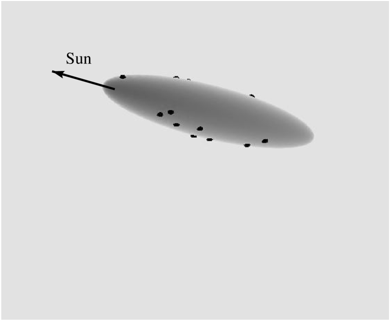
Given the limited number of instantaneous baselines, for a mission with significant solar science objectives, it would be desirable to have all of them to be sensitive to solar emission. For an Unwin sphere kind of constellation this suggests a maximum diameter of for the sphere, leading to a resolution of at 111A baseline of provides a resolution of at .. In view of the anisotropy in the angular resolution requirements, it is worthwhile to consider the possibility of incorporating a corresponding anisotropy in the Unwin sphere configuration. In order to be able to provide higher angular resolution in other directions while keeping all the projected baselines, as seen from the Sun, sufficiently small, we propose to distribute the satellites in a quasi random manner on a Cigar shaped surface, respecting a similar minimum separation constraint as the Unwin sphere. The cigar can be about in length and about across at it’s center and oriented such that it always points in the direction of the Sun. Rather than regarding the spacecraft being placed on a geometric surface, it is more appropriate to regard them as being placed within a cigar shaped shell of finite thickness. Over a period of time, as the constellation goes around the Sun on it’s orbit, the long baselines which lie along the length of the cigar will sweep through a range of orientations, providing a good coverage of the -- volume needed for high resolution imaging of the celestial sphere.
An obvious limitation of this configuration is that all the long baselines lie in the ecliptic plane. Assuming that the total number of spacecraft in the constellation is a constant, the only way to remedy this is by removing some of the spacecraft from the cigar and deploying them such that they provide long baselines perpendicular to the ecliptic plane. Removing even a few spacecraft from the cigar reduces the number of useful baselines for solar observations considerably. Given the limited number of interferometer elements available, it is difficult to meet all these demands simultaneously.
An alternative approach for resolving the conflicting requirements of solar and astronomical imaging is that rather than trying to find less than perfect, compromise solutions for both sets of objectives simultaneously, divide the mission duration between the two and try to meet the requirements of only one of them at a time. An Unwin sphere whose radius a slowly increases from say to over the mission duration is a good solution for this approach. At small diameters the constellation is capable of fulfilling solar objectives and as the diameter grows, its ability to do solar science diminishes. The data gathered using the small diameter phase will, of course, be useful for astrophysical objectives as well, if a satisfactory solution to the problem of non-stationarity of the sky can be found (3.8). The gradual increase in the constellation radius will also provide a better -- coverage.
A detailed study, examining the imaging characteristics of different configurations and their compatibility with different scientific objectives, is needed to arrive at a suitable constellation configuration for a VLF interferometer. As has been mentioned earlier, the width of the spectral channel is related to the maximum baseline in the configuration. The current choice of wide spectral channels allows for maximum baseline lengths of beyond which decorrelation losses may be considered significant (Sec. 4.4). If the final configurations are much smaller in size, the spectral widths of the frequency channels can be increased leading to an increased RF bandwidth coverage while using the same telemetry bandwidth between the Mother spacecraft and the Earth.
4.6 Tackling the Radio Frequency Interference
As discussed in section 3.7, RFI will be a dominant issue for near Earth orbits and will remain an issue to contend with even for the far Earth orbits. There are two aspects of RFI seen by space based instruments, which make the problem different in character from the one faced by ground based instruments.
-
1.
A space based instrument benefits from the geometric dilution of the intensity of the RFI emission, where is the distance between the Earth and the satellite borne interferometer.
-
2.
Unlike being immersed in a sea of RFI, as on Earth, a space based instrument sees RFI to be coming from a specific direction in the sky, that of the Earth. To provide a point of reference, from a distance of , the Earth will remain unresolved by baselines at .
It is also important to keep in mind that in spite of practically the entire VLF band being allocated to specific users, the RFI spectral occupancy is much less than (probably closer to ) because of the frequency separation between transmissions on adjacent allocated frequency channels. The RFI ridden VLF band is interspersed by regions of relatively clean spectrum which can be utilised for radio astronomy. The wide spectral channels provide a good match to the frequency resolution needed to make use of the parts of the band between adjacent transmissions. We proposed the following to mitigate the harmful effects of RFI.
-
1.
In order to maximise the geometric dilution of RFI, it would be preferable to choose from among all available orbits the ones which place the constellation farthest from the Earth.
-
2.
The well defined directional nature of RFI will be exploited to identify and reject parts of the band with strong RFI. The astronomical observing will be periodically interrupted, at a low duty cycle, for RFI detection. The interferometer will sweep through the RF band of interest and will be configured to add the signal coming from the direction of Earth first constructively (in phase) and then destructively (out of phase). RFI is expected to show up as narrow band emission which appears when the signal from Earth is added in phase and drops when it is added out of phase. The differences in the spectra obtained in the two cases will be examined to identify RFI contaminated frequency channels, which will then be excluded from further processing. Frequency and time integration can be performed to improve the sensitivity of RFI detection, though at the price of a reduction in the time available for astronomical observations. By averaging in time for a minute and over four adjacent frequency channels, we expect to obtain detection of RFI at the level of of the Galactic background, which is quite satisfactory. The frequency with which this exercise is performed should match the time scale at which the RFI environment is expected to change. The data from WAVES experiment on-board WIND can be useful in this determination (Kaiser et al.,, 1996). As this scheme needs to examine the visibilities to identify RFI, it needs to be implemented on the Mother spacecraft. For optimal utilisation of the intra constellation telemetry bandwidth resource, a list of spectral channels identified as RFI contaminated will be transmitted to the constellation members. These identified channels will not be transmitted to the mother spacecraft and the list will be updated every time RFI detection is performed.
-
3.
While it is possible to identify the relatively strong RFI in short time integrations, it is much tougher to identify weaker RFI and prevent it from contaminating the data. Fortunately for a space borne array, its highly directional nature ensures that the residual RFI which sneaks in will map on to a specific predictable direction in the sky, the direction of the Earth. This direction will trace out the path followed by the Earth in the sky, as seen from the array. Hence rather than contaminating the entire map, the RFI signal will stay confined to this locus of the Earth through the sky. As the effect of RFI is localised in the image domain, it suggests that it will be useful to an entirely new class of RFI mitigation techniques, which work in the image domain, can be usefully employed.
4.7 Choice of orbits
In order to keep it feasible to maintain the constellation in the desired configuration, for the entire duration of the mission, it is necessary to restrict the choice of orbits to those where the differential gravity over the length scales of the constellation size is low. These orbits also allow the visibility data to be averaged for significant durations in time (many tens of seconds), reducing telemetry bandwidth requirements. This becomes possible because the relative positions of the spacecrafts, and hence the baselines, evolve only slowly in time. Distant Earth orbits provide comparatively better RFI environments as well (Sec. 4.6). The above considerations argue strongly in favour of distant Earth orbits. On the other hand, distant Earth orbits pose a tougher telemetry problem. None the less, we consider only distant Earth orbits to be suitable for this mission, especially in view of the fact that the proposed design reduces the telemetry intensive nature of the mission in a very considerable manner. Halo orbits about the L1 Lagrange point, distant retrograde and prograde orbits about the Earth-Moon barycenter at distances of from the Earth seem to be suitable candidates. The choice of orbits in the vicinity of the L1 Lagrange point imply that the interferometer will always be facing the sunlit side of the Earth. This will lead to a better shielding from the extremely intense terrestrial auroral kilometric radiation (Gallagher and Gurnett,, 1979) and will be advantageous for the solar and astronomical scientific objectives.
5 Data analysis strategy
The primary focus of this work is to present a VLF interferometer design optimised to provide visibilities with as little loss of information as possible and maximises the RF bandwidth of observation. The intent is to make the task of imaging more tractable and better address the scientific objectives. The inversion of the visibilities received on the Earth to arrive at the brightness distribution in the sky will be a non-trivial task and forms an independent area of research. The problem of inverting VLF interferometer visibilities is more involved than the one faced by existing interferometers because of the a near FoV (Sec. 3.4) and the fact that the non-stationarity of the sky will need to be taken into account (Sec. 3.8).
The earlier proposals for VLF interferometers sought, without much success, to reduce the FoV to be mapped by trying to use more directional elements (Weiler et al.,, 1988; Basart et al.,, 1997). As it is not possible to build directional receptors smaller or comparable in dimensions to the wavelength of operation, the space based VLF interferometer will have no other option but to have practically omni directional beams, till the time technology allows the deployment of structures, a few in size, in space. A later attempt intended to use the bandwidth decorrelation effect to limit the region of sky from which correlated radiation is received (Jones et al.,, 2000). This is not an entirely satisfactory solution to the problem because, as was pointed out in Sec. 3.4, this leads visibilities coming from different baselines to pick up correlated emission from sky patches of different orientations and sizes.
We wish to point out that these attempts to limit the fields of view to be mapped were driven by the fact that it was inconceivable then to envisage that the computing power required to image near all-sky fields of view will become available in the foreseeable future. Hence, in spite of being mathematically well formulated, the task of simultaneous all sky imaging was never feasible. The recent enormous increase in the computational power available at affordable costs and the continued adherence to Moore’s Law will soon bring the computational requirements for all-sky mapping with reach, eliminating the need for reducing the region to be mapped. It is now time to start considering the simultaneous all sky coverage provided by the near omni-directional beams as an advantage over other wavelength ranges in astronomy which are limited to narrower fields of view.
We propose to map the entire primary beam of receiver elements. The visibilities obtained will be gridded over the three dimensional u-v-w space and will lead to a three dimensional image volume using the full three dimensional inversion formalism (Perley,, 1999). The intersection of the image volume with a unit sphere represents the celestial sphere, the object of interest. The dimensions of the visibility cube on which to grid the data will be arrived at using the criteria that the resulting image volume should Nyquist sample the entire sky with the resolution of the constellation. The choice of mapping the entire primary beam impacts the design of the interferometer in a considerable manner.
The data analysis techniques must have the ability to deal with the non-stationarity of the sky. As the Sun will be the strongest non-stationary source, the bulk of the problem can be diminished by simply resolving out solar emission. This is however not compatible with solar science objectives and the small baselines are required to capture the intense galactic background. Strictly speaking the data accquired by the VLF array over a period of time cannot be combined to produce a single sky map without first removing from it the contamination due to the non-stationary sources. One possible way of doing it might be to use an all-sky model for the stationary sky and subtract it’s contribution from the measured visibilities. The residual visibilities will then represent the contribution of the non-stationary part of the sky, which is also expected to have significant time and frequency structure. The overlap in frequency range with ground based instruments will provide the VLF interferometer a good sky-model from where to boot-strap to lower frequencies.
6 Calibration and formation flying
The aim of any calibration procedure is to estimate the response function of the measuring instrument. In synthesis imaging this has conventionally been done by observing astronomical sources with known properties (position, strength, structure, polarisation etc.). This approach relies on the availability of a field of view which is dominated by a single (or at most a few) strong sources with known properties. The near field of view of the present instrument coupled with the intense Galactic background in the VLF range eliminate this possibility, except in case of some solar bursts, which usually have an elaborate frequency time structure. It will, hence, not be possible to routinely rely on astronomical sources for calibrating the interferometer. There will be no choice but to seek engineering solutions to meet the calibration requirements.
Complex gain of the receivers will be calibrated by periodically injecting a known complex calibration signal into the signal path just after the dipoles and comparing the output from the receiver with the input signal. Comparisons with observations from the ground based instruments at the higher end of the VLF range and simultaneous observations of bright transients like solar bursts by other space and ground based instruments can be used for amplitude calibration. Dulk et al., (2001) have shown that for the low resolution single element instruments at low frequencies, the Galactic background spectrum offers a more reliable means for flux scale calibration. This can be used to obtain an independent estimate the gains of individual constellation members. The complex primary beam of the dipoles will have to be measured on the ground, before the launch of the mission. Mounting the dipoles on the spacecraft will considerably modify the beam shapes from those of isolated dipoles. The beam shapes must, hence, be characterised after the dipoles have been mounted on spacecraft. In flight calibration of beam shapes, if needed, will require some additional on-board functionality. It can be achieved by radiating a signal of known characteristics from one or few of the constellation members, receiving it on the others and processing it suitably.
The formation flying requirements relate directly to the wavelength of operation of the interferometer. Working at the longest possible wavelengths, a VLF interferometer has the least demanding formation flying requirements. This makes a VLF interferometer an ideal choice for testing the formation flying mission control and management concepts. While infra-red space interferometers, like DARWIN (Leger et al.,, 1996) require the constellation members to be positioned with relative accuracies of the order of a , for a VLF interferometer it is not necessary to fly the constellation in a rigid pre-defined configuration at all. Departures of individual spacecrafts from their intended positions, by small fractions of the characteristic length scale of the configuration, do not degrade the performance on the interferometer in any significant manner. The mission requires the baselines to be calibrated to an accuracy of at the smallest wavelength of observation ( at ). It is however not necessary to know the relative positions of the constellation members to this accuracy in real time. Real time baseline accuracies only need to be sufficient to ensure that the correlation between the signal received at different satellites is not reduced significantly. Real time accuracies of the order of a few will be quite acceptable. The final accuracies, made available by the post facto orbit reconstruction, must however meet the more stringent requirement. Once the baseline are known to final required accuracies, offline corrections can be applied to the computed visibilities. Being far away from the Earth, it will not be possible for the mission to make use of the existing Global Positioning System (GPS) satellite network for locating the satellites. An on-board ranging and direction finding system will be required.
The intra constellation ranging and direction finding data is insensitive to an overall rotation of the array, which will need to be determined by independent means. There is also a need to align the relative orientations of constellation members (attitude control), to ensure that the dipoles on different spacecrafts are pointed in the same directions. A star tracker unit on board every constellation member will be used to serve both these purposes. As the FoV of dipoles are huge, attitude control of the order of a degree is probably already an over kill.
The time synchronisation requirements for the constellation do not pose a challenge. As the design does not require a local oscillator, there is no requirement to distribute a phase locked signal to all spacecrafts. The only requirement for time synchronisation comes from the coherence time of the signal, which is . For channel widths of , this amounts to an embarrassingly comfortable . Given that the relative positions of the spacecrafts will be known to a few , it will be preferable to time tag the time series of spectra from different constellation members on the Mother spacecraft, taking into account the changing light travel time and the fixed delay due to the signal processing.
7 Conclusions
Very low frequency radio astronomy is now coming of age. The advances in technology have finally brought us at the brink of opening this last unexplored window in the electromagnetic spectrum, both from ground and space. A versatile and powerful low frequency interferometer, LOFAR, is envisaged to commence operation later this decade, pushing low frequency radio astronomy to its furthest limits achievable from the ground. A space based array will benefit considerably from the knowledge of the low frequency sky gained from this ground based array and will form the next logical step of pushing the exploration of the VLF window to its absolute limits. Exploiting the advances in space qualified technology and the vast increase in computing capabilities, one can now design space borne VLF interferometers with capabilities way beyond the earlier proposals. The currently available technology comes very close to meeting the requirements of this new design in most respects. We believe that the returns from this approach will amply justify the rather short wait for the technology to deliver the needs of a VLF interferometer. This design offers many advantages over the conventional approach. It permits the RF bandwidth covered to be increased by more than an order of magnitude. The simultaneous digitisation of the entire RF bandwidth of interest offers the flexibility of distributing the part of it to be processed further in any manner from a few to , a considerable advantage for multi frequency synthesis and for simultaneously covering a large spectral window. A flexible and reconfigurable correlator design can be used to set observation parameters to suit different science needs and evolve the observing strategy as we learn during mission operation. The data it provides is compatible with the scientific objectives of the mission.
A disadvantage of the design is that as it requires a Mother spacecraft, the redundancy in the constellation is considerably reduced. To counter this, it will be essential to equip a few spacecraft to take up the role of a Mother spacecraft in case of need. This does not seem to pose an unsurmountable problem. This design does require a more complex payload than the conventional approach, but the level of complexity is not large in an absolute sense. The intra constellation telemetry is presently envisaged to be the most constraining bottle neck. This is an area which has received little attention by the space industry till now, simply because none of the existing space missions needed this functionality. Formation flying missions are now being vigourously pursuing by the space industry and the requirement of intra-constellation telemetry will be shared by many of them. As this requirement gets better recognised we expect suitable technological solutions to emerge.
The steady increase in performance of space qualified hardware,
formation flying and computing capabilities, place the demands of
a satellite based interferometer within reach in near future. It
is, hence, timely to lay down a design for a space low frequency
interferometer, based on realistic expectations for technology
available in near future and assess its scientific desirability.
The VLF interferometer concept is now mature enough to merit a
detailed engineering study.
Acknowledgements.
We acknowledge the fruitful and illuminating discussions with Alain Kerderaon, Claude Mercier, Sanjay Bhatnagar, Pramesh Rao, Tim Bastian, Brian Corey, Will Aldrich and Brian Fanous at various stages during this study. This research has made use of NASA’s Astrophysics Data System Abstract Service. All the this work was done using the GNU/Linux operating system and it is a pleasure to thank the numerous contributors to this software.References
- Alexander, (1971) Alexander, J. K. (1971). New Results and Techniques in Space Radio Astronomy. In IAU Symp. 41: New techniques in Space Astronomy, volume 41, pages 401–+.
- Alexander et al., (1975) Alexander, J. K., Kaiser, M. L., Novaco, J. C., Grena, F. R., and Weber, R. R. (1975). Scientific instrumentation of the radio-astronomy-explorer-2 satellite. A&A, 40:365–371.
- Basart et al., (1997) Basart, J. P., Burns, J. O., Dennison, B. K., Weiler, K. W., Kassim, N. E., Castillo, S. P., and McCune, B. M. (1997). Directions for space-based low frequency radio astronomy. 1. system considerations; 2. telescopes. Radio Science, 32:251–275.
- Bougeret, (1996) Bougeret, J.-L. (1996). Very low frequency radio astronomy. Advances in Space Research, 18:35–41.
- Bougeret et al., (1995) Bougeret, J.-L., Kaiser, M. L., Kellogg, P. J., Manning, R., Goetz, K., Monson, S. J., Monge, N., Friel, L., Meetre, C. A., Perche, C., Sitruk, L., and Hoang, S. (1995). Waves: The Radio and Plasma Wave Investigation on the Wind Spacecraft. Space Science Reviews, 71:231–263.
- Bracewell and Preston, (1956) Bracewell, R. N. and Preston, G. W. (1956). Radio Reflection and Refraction Phenomena in the High Solar Corona. ApJ, 123:14–+.
- Bridle and Schwab, (1999) Bridle, A. H. and Schwab, F. R. (1999). Bandwidth and Time-Average Smearing. In ASP Conf. Ser. 180: Synthesis Imaging in Radio Astronomy II, pages 371–+.
- Carozzi et al., (2000) Carozzi, T., Karlsson, R., and Bergman, J. (2000). Parameters characterizing electromagnetic wave polarization. Phys. Rev. E, 61:2024–2028.
- Cordes, (2000) Cordes, J. M. (2000). Interstellar Scattering: Radio Sensing of Deep Space Through the Turbulent Interstellar Medium. In Radio Astronomy at Long Wavelengths, pages 105–+.
- Cordes and Lazio, (2002) Cordes, J. M. and Lazio, T. J. W. (2002). A New Model for the Galactic Distribution of Free Electrons and its Fluctuations. ApJ, submitted, astro-ph/0207156.
- Dulk, (2000) Dulk, G. A. (2000). Type III Solar Radio Bursts at Long Wavelengths. In Radio Astronomy at Long Wavelengths, pages 115–+.
- Dulk et al., (2001) Dulk, G. A., Erickson, W. C., Manning, R., and Bougeret, J. L. (2001). Calibration of low-frequency radio telescopes using the galactic background radiation. A&A, 365:294–300.
- Duric, (2000) Duric, N. (2000). Low-Frequency Radio Astronomy and the Origin of Cosmic Rays. In Radio Astronomy at Long Wavelengths, pages 277–+.
- Dwarakanath, (2000) Dwarakanath, K. S. (2000). What Would the Sky Look Like at Long Radio Wavelengths? In Radio Astronomy at Long Wavelengths, pages 257–+.
- Enßlin and Gopal-Krishna, (2001) Enßlin, T. A. and Gopal-Krishna (2001). Reviving fossil radio plasma in clusters of galaxies by adiabatic compression in environmental shock waves. A&A, 366:26–34.
- Erickson, (1990) Erickson, W. C. (1990). Radio noise near the earth in the 1-30 mhz frequency range. In LNP Vol. 362: Low Frequency Astrophysics from Space, pages 59–69.
- Erickson, (2000) Erickson, W. C. (2000). Long Wavelength Astrophysics. In Radio Astronomy at Long Wavelengths, pages 237–+.
- Gallagher and Gurnett, (1979) Gallagher, D. L. and Gurnett, D. A. (1979). Auroral kilometric radiation - Time-averaged source location. J. Geophys. Res., 84:6501–6509.
- Gopalswamy, (2000) Gopalswamy, N. (2000). Type II Solar Radio Bursts. In Radio Astronomy at Long Wavelengths, pages 123–+.
- Haslam et al., (1982) Haslam, C. G. T., Stoffel, H., Salter, C. J., and Wilson, W. E. (1982). A 408 mhz all-sky continuum survey. ii - the atlas of contour maps. Astronomy and Astrophysics Supplement Series, 47:1+.
- Herman et al., (1973) Herman, J. R., Caruso, J. A., and Stone, R. J. (1973). Radio astronomy explorer (rae)-i. observations of terrestrial radio noise. Planetary and Space Science, 21:443+.
- Jones et al., (2000) Jones et al., D. L. (2000). The Astronomical Low Frequency Array: A Proposed Explorer Mission for Radio Astronomy. Radio Astronomy at Long Wavelengths, Geophysical Monograph Series, 119:339–349.
- Kaiser et al., (1996) Kaiser, M. L., Desch, M. D., Bougeret, J. L., Manning, R., and Meetre, C. A. (1996). Wind/waves observations of man-made radio transmissions. Geophysical Research Letters, 23:1287+.
- Kassim and Weiler, (1990) Kassim, N. E. and Weiler, K. W., editors (1990). Low Frequency Astrophysics from Space, volume 362 of Lecture Notes in Physics. Springer Verlag. Proceedings, Crystal City, Virginia 1990.
- Ladreiter et al., (1995) Ladreiter, H. P., Zarka, P., Lecacheux, A., Macher, W., Rucker, H. O., Manning, R., Gurnett, D. A., and Kurth, W. S. (1995). Analysis of electromagnetic wave direction finding performed by spaceborne antennas using singular-value decomposition techniques. Radio Science, 30:1699–1712.
- Lecacheux et al., (1989) Lecacheux, A., Steinberg, J.-L., Hoang, S., and Dulk, G. A. (1989). Characteristics of type III bursts in the solar wind from simultaneous observations on board ISEE-3 and Voyager. A&A, 217:237–250.
- Leger et al., (1996) Leger, A., Mariotti, J. M., Mennesson, B., Ollivier, M., Puget, J. L., Rouan, D., and Schneider, J. (1996). The DARWIN Project. Astrophysics and Space Science, 241:135–146.
- Linfield, (1996) Linfield, R. P. (1996). Ipm and ism coherence and polarization effects on observations with low-frequency space arrays. Astronomical Journal, 111:2465+.
- MacDowall et al., (2003) MacDowall, R. J., Lara, A., Manoharan, P. K., Nitta, N. V., Rosas, A. M., and Bougeret, J. L. (2003). Long-duration hectometric type III radio bursts and their association with solar energetic particle (SEP) events. Geochim. Res. Lett., 30:6–1.
- Manning, (2000) Manning, R. (2000). Instrumentation for Space-Based Low Frequency Radio Astronomy. In Radio Astronomy at Long Wavelengths, pages 329–+.
- Perley, (1999) Perley, R. A. (1999). Imaging with Non-Coplanar Arrays. In ASP Conf. Ser. 180: Synthesis Imaging in Radio Astronomy II, pages 383+.
- Platania et al., (1998) Platania, P., Bensadoun, M., Bersanelli, M., de Amici, G., Kogut, A., Levin, S., Maino, D., and Smoot, G. F. (1998). A Determination of the Spectral Index of Galactic Synchrotron Emission in the 1-10 GHz Range. ApJ, 505:473–483.
- Reynolds and Begelman, (1997) Reynolds, C. S. and Begelman, M. C. (1997). Intermittant Radio Galaxies and Source Statistics. ApJ, 487:L135+.
- Reynolds, (1990) Reynolds, R. J. (1990). The low density ionized component of the interstellar medium and free-free absorption at high galactic latitudes. In LNP Vol. 362: Low Frequency Astrophysics from Space, pages 121–129.
- Rickett and Coles, (2000) Rickett, B. J. and Coles, W. A. (2000). Scattering in the solar wind at long wavelengths. Radio Astronomy at Long Wavelengths, Geophysical Monograph Series, 119:97–103.
- Stone et al., (2000) Stone, R. G., Weiler, K. W., Goldstein, M. L., and Bougeret, J. L., editors (2000). Radio Astronomy at Long Wavelengths, volume 119 of Geophysical Monograph. American Geophysical Union. AGU Chapman Conference, Paris, 1998.
- Weiler, (1987) Weiler, K. W., editor (1987). Radio Astronomy from Space, volume 18. National Radio Astronomical Observatories. Proceedings, Green Bank, W. Virginia 1987.
- Weiler et al., (1988) Weiler, K. W., Johnston, K. J., Simon, R. S., Dennison, B. K., Erickson, W. C., Kaiser, M. L., Cane, H. V., and Desch, M. D. (1988). A low frequency radio array for space. A&A, 195:372–379.
- Woan, (2000) Woan, G. (2000). Capabilities and limitations of long wavelength observations from space. Washington DC American Geophysical Union Geophysical Monograph Series, 119:267–276.