A Model for ‘Double Notches’ in Radio Pulsar Profiles
Abstract
Aberration and retardation of the radiation within a pulsar’s magnetosphere enable a single corotating absorbing region in the outer magnetosphere to give rise to a ‘double notch’ in the pulsar’s observed radio profile. This effect requires that a pulsar has not only absorbing but also emitting regions at heights which are a significant proportion of the light cylinder radius. The known presence of double notches in the weak secondary emission of three nearby pulsars suggests that this emission comes from open field lines well above their poles and that an obscuring region extending over no more than 5 percent of the light cylinder radius is located at or near the light cylinder.
1 INTRODUCTION
1.1 Background
It is known that at least three pulsars have mysterious double ‘notches’ in their integrated profiles (McLaughlin Rankin 2003, henceforth MR). All are also known to be sources of pulsed X-rays (Wang Halpern 1997, Zavlin et al 2002), and PSR 1929+10 and PSR 0950+08 also have optical identifications (De Luca et al 2003, Mignani et al 2002, Zharikov et al 2003). Their high-energy spectra have variously been interpreted as polar cap thermal emission sustained by particle backflow or as non-thermal cyclotron emission, with the latter being a particularly strong indicator of outer magnetospheric activity. Since one of the three is a millisecond pulsar and the other two are slow normal pulsars they would seem to have little in common - even their magnetic fields computed at the light cylinder differ by several orders of magnitude. The only intrinsic factor all three have in common is a similar ”acceleration parameter”, a measure of the potential difference available to accelerate particles within the magnetosphere.
The three pulsars are nearby and, possibly because of this, have detectable weak emission though a large fraction of their periods. The double notches are embedded in the weak emission and MR report that the phase of their centroid is frequency-independent, although their width and separation seems to be frequency-dependent and the feature may not be seen at all at some frequencies. These are the salient points on which an explanation must be built.
One piece of obvious and valuable information to be gleaned from the observations is the physical scale of the phenomenon. This can be inferred from the notch separation, which MR report to be around for the normal pulsars and for the millisecond pulsars. One might seek an explanation in terms of unusual surface composition or magnetic field structure, which would then imply a lateral scale very small compared to the polar cap dimensions. But we would then require that such ’freak’ conditions existed on a similar scale in three very different pulsars. In this paper we offer an explanation based on the effects of aberration and retardation, leading to physical scales based on light-travel times. The notches may thus corespond to lateral or longitudinal features on a scale up to one sixth of a light cylinder radius (or 2000km in the case of PSR 0950+08 and PSR 1929+10 and just 20km for PSR J0437-4715), a scale far greater than inferred height variations for polar cap emission of a single frequency (Gupta Gangadhara 2003, Dyks et al 2003a). This suggests that the emission in and around the notches comes from regions higher in the magnetosphere - an idea which is important since, if true, it would demonstrate support for a long-held suspicion (e.g. Arons 1979, Hankins Cordes 1981, Gil 1985) that not only new-born but also older normal pulsars are capable of emitting at radio frequencies in the outer magnetosphere.
To account for notches in such emission it is natural to turn to the possibility of an obscuring region lying between the emitting region and the observer. Luo Melrose (2001) and Fussell et al (2003) have suggested that regions of emission suppression can arise in a pulsar magnetosphere as a result of cyclotron absorption. Clearly any obscuring feature must lie within the magnetosphere and corotate with it or the notches would not appear at a fixed phase of the pulse window. The size of the obscuration estimated from the width of the individual notches comes out as 600km in the case of PSR 0950+08, 400km in the case of PSR 1929+10 and a tiny 5km for PSR J0437-4715. Such scales are not impossible to envisage: perhaps a region of locally-enhanced particle density at high energies located either at the light cylinder or on the boundary of the corotating zone defined by the last fieldlines to close within the light cylinder. But how do we explain notches?
It is most unlikely that obscuring regions lie adjacent to one another at any location in the magnetosphere at a fixed or frequency-dependent separation from one another. It would not correspond to any known feature from theory or observation. So instead we turn to one of the unique properties of a pulsar magnetosphere to provide us with a possible explanation. Pulsar magnetospheres differ from conventional magnetospheres in that the particles move tightly bound to magnetic fieldlines and emit their radiation in a extraordinarily narrow beam. This implies that most regions of the magnetosphere are invisible to the observer at any given instant. We will show in this paper that under these circumstances it is possible for a single obscuring region to produce a double notch effect, and in such a way that observed features of the notches enable us to deduce a simple relation between the location of the emitting and obscuring regions.
Section 2 summarises the basic principles employed in the model, and Sections 3 and 4 give the detailed geometric calculations for the cases of radial and dipolar fieldlines respectively. Section 5 applies the results to MR’s observations of the three candidate pulsars, and Section 6 summarises the implications and conclusions for future high-energy observations.
2 BASIC FEATURES
2.1 Model outline
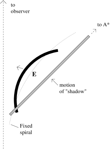
To demonstrate the central idea of this paper we first consider a simple two-dimensional model of radially-directed sources moving relativistically and rotating perpendicularly about a central axis. The radiation from those lying towards the centre will be subject to weak aberration, but those further out towards the light cylinder will have their motion, and hence their radiation, strongly diverted from the radial vector in the observer’s inertial frame. The further a source is from the centre, the sooner its radiation will be directed towards the observer, since its greater angular motion will yield greater aberration. At any given moment, all sources in the magnetosphere whose radiation is instantaneously directed towards the observer must lie on a spiral centred on the axis and fixed in relation to the observer (depicted as a finely-dotted curve in Fig 1). As the magnetosphere turns, sources will pass across this spiral and, if at an appropriate frequency, will be detected by the observer.
Furthermore, as a consequence of retardation, the sources will be observed in contrary sequence to which the radial vectors are presented to the observer (ie counter to the direction of the rotation) : those most distant from the axis will be seen first, those near the centre last. In the case of a single radial vector of such emitters extending almost to the light cylinder, up to a third of the rotation period will elapse (instead of one sixth if retardation were neglected) before all of them are seen. This would be perceived as nearly in phase and would be greater still if the vectors were not radial but led into the sense of rotation. It is suggested here that the weak coherent emission observed in a number of radio pulsars through a wide range of pulse phase arises through this effect.
Within this two-dimensional picture, we postulate the existence of a corotating site A*, located within the light cylinder (radius ) at a distance of from the star, which is capable of absorbing all incident radiation. Once it subtends less than a critical angle (thus always less than one radian) with the observer’s line of sight, such a site will subsequently be able to absorb radiation from sources on the section of the observer’s spiral extending from the rotation axis to the location of A*, and hence its effect will be detectable by a distant observer. As it swings towards the observer’s line of sight, each position of A* defines an instant when separate sources on the spiral, one closer to the axis, one closer to A*, emit radiation which will subsequently be absorbed by A* at the radius . Clearly the site closer to the axis will be absorbed later than the other. In this way A* throws its ”shadow” : a line drawn between the two obscured sites always points at the current location of A* and always intersects the observer’s line of sight at the same angle (). This result is illustrated in Fig 1, and the formal geometry of the model is set out in Section 3.

|
Fig 1 summarises the three phases of the process. In the first phase, as the absorber turns towards the observer’s line of sight between and , it defines two changing locations on the spiral from which the momentary emitted radiation will be later absorbed. As A* approaches these locations draw together, finally becoming briefly a single location E (and just before, a narrow pair), located at a radius , after which no further emission can take place which will subsequently be absorbed. At the conclusion of the first phase the absorber will sustain an angle to the line of sight and E will lie further in, exactly half way between the original angular position of A* and the observer’s line of sight. This crucially determines the fixed angle between E and A* as . Compounding this with the aberration () and retardation () accompanying the emission from and around E, we conclude that the double notches are observed at a phase ahead of the phase of A*.
In phase two, which is exactly twice as long as phase one, A* continues to rotate and absorb radiation previously emitted from the upper section of the fixed spiral. When A* is at and from the line of sight it absorbs the emission from E - and just before and after this moment it absorbs in rapid succession the radiation emitted from the narrow pair of emitters on either side of E, causing the observer at an appropriate frequency to see a double notch.
Finally, in a third phase equal in length to the first, A* traverses the remaining quarter of the arc to the point where it lies precisely on the observer‘s line of sight, and during this time sequentially absorbs the previously emitted radiation from sources below E at the midpoint of the spiral down to the surface of the star.
In reality only a small fraction of a pulsar magnetosphere may be radiating coherently, and certainly not universally at the same frequency. But the most obvious difference between the above model and real pulsars is that the fieldlines will not be aligned in a radial direction. In Section 3 we modify the previous picture so that the emission which is to be absorbed is directed at the same fixed angle to the radial vector (although coming from different sources and in general lying on different fieldlines). We find that as long as the angle (either trailing or leading) is no greater than a double-absorption feature can again be generated by a corotating absorber. However the absorber will now be located at a radius greater than the sum of the heights of the obscured sources for leading fieldlines and less for trailing fieldlines. Nevertheless it can be shown that the differential between the observed phase of the notches and the phase of A* is only weakly dependent on the fieldline inclination.
In the final part of Section 4 it is demonstrated that for emitting systems with the rotation axis and the observer’s line of sight inclined at an angle , the effects of aberration will be weaker and the allowed heights of the absorbed emission and the absorbing region will increase from the perpendicular case by a factor . Nevertheless the phase shifts in the pulse profile can be interpreted using the same formalism.
2.2 Observational inferences
In Section 5, armed with the above results, and with and as the only free parameters, we take the data of the three pulsars given by MR and attempt to infer the true positions in the magnetosphere of the emission surrounding the notches and of their corresponding absorbing regions.
Assuming PSR 1929+10 is a perpendicularly rotating dipole, we demonstrate that the notch can be generated by an absorbing region close to the light cylinder and a near-vertical or convex band of emission ahead of the polar axis, suggesting that the observed weak inter-pole emission and its position angle sweep may be the relativistic consequence of such a band or bands.
A similar model was found possible for PSR 0950+08, but without implying orthogonality. A single band of emission leading upwards from the pole (assumed to be located at the main pulse) towards the light cylinder, may account for the observed weak emission, with the interpulse representing some feature in the outer magnetosphere near the light cylinder. The absorbing site would also be at the light cylinder radius, some ahead of the point on the band whose emission is absorbed. The pulsar should neither be near alignment nor near orthogonality.
Finally it is shown that the ”late” notches of PSR J0437-4715 can be modelled as long as the pulsar is assumed to be at a low angle of inclination. Then both the obscuring and obscured regions must be relatively close to one another at heights above the star greater than the light cylinder radius. However, fieldlines are preferred which lie within the upper open zone of the magnetosphere, but not necessarily the last open fieldlines.
A summary of the conclusions, dicussing the consequences of these results for future radio and high-energy observations of these pulsars, are given in Section 6. It is stressed that the polar cap and the outer magnetosphere may exist in an interactive state in these and other pulsars (Wright 2003), as is hinted at by recent simultaneous multifrequency observations of the Crab (Shearer et al 2003) and Vela (Donovan et al 2003) pulsars.
3 Geometric Basis
To formally demonstrate the geometric principle of double obscuration we adopt the two-dimensional picture of Fig 2, in which a source S at a radius r is rotating about O at a fixed angular rate of . In a rotating frame the emission is radially directed away from O, but in the inertial frame this results in an aberration component perpendicular to OS. The resultant direction of the emission is then instantaneously towards an observer indicated at the top of the page, making an angle with OS of
| (1) |
where c is the speed of light and the light cylinder radius.
A site at which all incident radiation is assumed to be absorbed is also rotating at a rate and located at a distance and making a permanent angle of with OS. If at a time t=0 S is positioned so that its radiation (subject to aberration) is directed towards the observer, then the radius vector of the absorber will at that moment make an angle with the direction to the observer, given by
| (2) |
Since is the angle the source’s postion vector makes with the observer’s line of sight, (2) defines the equation of the critical spiral. We need to know for which coordinates (r,) of S will the radiation from S be absorbed before it reaches the observer (ie we seek to know from which position or positions on the spiral will the radiation be absorbed by A*). Represented in Fig 2, this requires that has rotated to a new position in the same time that the radiation has travelled from S to . If , the angle between the new vector and the t=0 vector for S, is assumed to be small (as it will be if the aberration effect is small), then the distance travelled by the radiation before absorption will be () and is given in the small angle approximation by
| (3) |
hence from (1)
| (4) |
The crucial condition that A* rotates to in the same time, T, that the radiation travels from S to is then
| (5) |
which yields from (4)
| (6) |
and, substituting from (2), we obtain a quadratic for r:
| (7) |
3.1 Double Obscuration
The two solutions of equation(7) represent two possible locations at which an emitter S can be obscured by as it rotates. These solutions satisfy
| (8) |
and for both these roots to be positive we additionally require that , or
| (9) |
Given that must be less than unity, we have our first constraint on the position of the absorber, namely that if radiation is to be absorbed then it must be emitted when the absorber’s radial vector bears an angle less than one radian (about ) to the observer’s line of sight, and in practice much less.
The difference (i.e.the approximate distance) between the two locations is
| (10) |
so that
| (11) |
and the physical condition that is real, together with (9) above, establish the upper and lower limits on as
| (12) |

|
where
| (13) |
ie only when A* is between these two angular positions can radiation be absorbed. This defines the duration of Phase 1, at the conclusion of which and the two possible solutions for the position of S coalesce to the position E in Fig 1.
The upper limit is only appropriate when and . The more interesting case here is when and are close to each other and is located at . Through Phase 1, as decreases from , the positions of and gradually move along the spiral towards each other, meeting at the lower limit of (13) and fixing the location of E in Fig 1 on the critical spiral. Hence in general a narrow extended absorbing region centred radially or azimuthally on A* will at any moment obscure two strips of the dotted spiral on either side of the midpoint, as indicated in Fig 1.
3.2 The relative geometry of the two obscured regions
The location of is at an angle
| (14) |
to the vector of A* (and is at the equivalent angle ). Thus at the moment of emission the angle between and the midpoint of and is
| (15) |
so that at or close to the conclusion of phase 1, when , we can establish the angle between the observed mid-point of the notches and the site of the absorber as
| (16) |
Thus is less than , and can never be more than .
To measure the duration of phase 2 we need to evaluate , the angle between the initial position of the emitter and the position at which its emission is absorbed. It is the same for both emitters:
| (17) |
When and are close to the midpoint, both and . So in geometric terms OS bisects the angle between and OA*, and in phase 2 A* rotates through , twice the angular duration of phase 1.
We can show that the line joining the two solutions always points at the current position of A* and makes an invarying angle to the observer’s line of sight. The angle SA*O which S makes to the absorber’s vector is the same for both solutions since it is given by
| (18) |
(from (14)), and the direction SA* makes with the observer’s line of sight () is, from (2) and (18),
| (19) |
which is the same for all , and implies that the two obscured sources always point towards A* and remain aligned parallel to the original direction of A*. The line between the sources acts as a kind of ”shadow” of A* which passes across the observer’s spiral. But the ”shadow” moves rapidly, passing over the entire spiral during phase 1, as A* physically rotates through an angle . By then it has crossed fieldlines from the original position of OA* ( in Fig 1) to OS, which is now an angle (OE in Fig 1) to the observer’s line of sight. Hence the ”shadow” can be perceived as moving at twice the rotating speed of the fieldlines, continuing to overtake them until it passes through E (see Figs 1 and 3).
This has the further consequence that an absorber extended along or perpendicular to OA* will not have its ”shadow” on the observer’s spiral expanded by the geometry, but will project its size along parallel lines. Hence the observed notch width can be taken as an approximate measure of the absorber’s dimensions.
Phase 2 closes with the emission from E absorbed by A*, which is now at in terms of Fig 1. In Phase 3, the absorber moves to position itself precisely between the observer and the star, and as it turns absorbs the radiation earlier emitted from the lower section of the fixed spiral, finally absorbing the emission from O.
We are now able to evaluate the crucial time intervals necessary for interpreting the observed apparent phase of the double notches in a pulsar profile. First we need the phase delay between the emission from E and the moment at which it absorbed at (i.e. the end of Phase 2). This is the sum of the emission’s retardation () and its aberration (), giving
| (20) |
Then from (16) we know that the fixed angle between the midpoint of the notches and the alignment of the absorber is , so we can finally say that in an aligned rotator of radially beamed emitters any observed double notches will lead the true position of their absorbing site by a phase of
| (21) |
Both (20 and (21) are only accurate if , and can only be approximate in our later attempts to consider cases where .
4 Modifications for dipole geometry
Before we can apply the above results to the three pulsars described by MR in the companion paper, we first consider how they must be modified to describe sources which are constrained to radiate parallel to dipolar field lines, and furthermore that the dipole may take any angle to the rotation axis. We consider each of these points in turn.
4.1 Non-radial fieldlines
Firstly, although dipolar fieldlines will be non-radial and splay apart from the polar cap, we will continue to assume that the observed fieldlines lie in a two-dimensional plane (as in the case of a perpendicular rotator). But in general we will assume that at every position the source radiates at an angle () to the radial direction. The sign of indicates whether we are approximating trailing () or leading () fieldlines, and will in general be both radially and azimuthally dependent, and hence time-dependent.
To direct radiation from the source S in Fig 2 towards the observer, aberration must now shift the propagation vector not through but through the total of and , which may be greater (trailing) or less (leading) than . This modifies our result (1) to
| (22) |
so that now the deviation due to aberration is
| (23) |
Note that if the aberration is still ahead of the radial vector. But for the sources do not emit in the direction of the observer until their radial vectors have passed through the observer’s line of sight. If is constant, (23) is the equation of a new fixed spiral, analogous to that in Fig 1, shifted by the fixed angle in the sense of the rotation if , and against it if .
Following the argument of the previous section, we again apply the condition that the absorber rotates precisely to meet the observer-directed radiation, and this yields a modified value for the fixed angle between OA* and OS:
| (24) |
whence we obtain a new quadratic for r:
| (25) |
So far we have allowed to be a radially and azimuthally dependent function. This would make (25) a model-dependent and time-dependent equation to yield the locations of the sources whose emission is absorbed. However, since for observational reasons we are ultimately interested in solutions for small emission regions close to E over which the magnetic field direction varies little, we will now take as a constant. The two roots of (25) are related by
| (26) |
and
| (27) |
We note immediately from (26) that for absorption to occur at two sites we mqust place the important constraint between and the radius of the absorber that
| (28) |
so that neither nor shall exceed (for ) nor be negative (for ). In what follows, we will therefore find that the sign-dependent ratio defined by
| (29) |
with , will be useful in highlighting the differences between the cases of radial and non-radial fieldlines.
However there is one important feature of the radial solution which remains unchanged. If we evaluate from (24) and (26) we now obtain
| (30) |
from which, using (23), we again have the angle S obtains at A*
| (31) |
which is the identical result to (18) and is the same for both obscured sources. And once more the line between the sources and the absorber makes an angle of with the observer’s line of sight.
4.2 Modified Phases
Although the observer’s spiral will be shifted by an angle either counter (leading fieldlines) or with (trailing fieldlines) the direction of rotation, it is clear from equation (26) that in either case only for can there be two physical roots to equation (25). As reduces, the double roots will begin with those at () and and end with
| (32) |
in the limit . This is the modified position of E, the limiting location of S on the spiral and the midpoint of the notches. Note how if it is located on leading fieldlines it will be closer to the surface of the star (for a given ) and further from it for trailing fieldlines. Then (by substitution in (25)) the absorber will be at the angle to the line of sight of
| (33) |
so that the total change in in Phase 1 is now
| (34) |
Given the constraint (28), even when (leading fieldlines) this quantity will never be less than zero. However it may be greatly reduced, limiting the time when double absorption is possible. Conversely, trailing fieldlines extend this possibility.
Setting into (30) we see that the source at E in Fig 1 will now lie at a fixed angle ahead of the absorber by
| (35) |
reduced in size and independent of the sign of on the result (16).
The time travelled by radiation from the modified position of E, given by the limit value of (32), to the absorber yields a modificaton in the angular duration of Phase 2:
| (36) |
In the case of leading fieldlines this is a significant increase on the equivalent angle in the purely radial case, because the reduction in the height of E means the time needed for the radiation to reach the absorber is longer. The effects are exactly opposite for trailing fieldlines.
We are again in a position to calculate the apparent phase shift between the observed location of the double notches and the ”true” phase in the magnetosphere of the vector defining their midpoint. Through aberration the midpoint is observed too soon (obtained by setting in (23)), and through retardation a further , giving a total of , identical to equation (20). Note that this quantity is independent of k for a given : a reduction in aberration is compensated by an increase in retardation and .
The additional phase separation between the midpoint’s vector and the position of the absorber is from equation (35), giving a total shift of , replacing equation (21). Thus the modification of this value compared with the radial case is small and independent of the sign of k.
4.3 Non-orthogonal rotators
In our deliberations so far the absorber, the sources and the observer’s line of sight all lie in the same plane orthogonal to the rotation axis. If our line of sight is not orthogonal to the rotation axis then an absorber rigidly circling the axis will only obscure a source whose emission, following aberration, lies in the near-instantaneous plane defined by the absorber and the line of sight. For this then to create a absorption feature is probably impossible in the poloidal fieldlines of a perfect dipole, but it cannot be excluded in the real field configuration containing swept-back poloidal components.
A full consideration of the 3-dimensional geometry would make the analysis extremely complex. However the closeness of the notches means that to a reasonable approximation we can again consider a geometry similar to Figs 1 and 2, where now all directions lie in approximately the same plane tangential to the cone formed by the rotating absorber with the star at its apex.
Assuming our line of sight passes close to the pole of the pulsar whose dipole axis is inclined at a general angle to the rotational axis, the aberration angle (1) at a given radial distance from the star must be modified by the factor , giving
| (37) |
In the plane of our geometry the replacement of with will effectively extend the corotating limit to and enable both the absorber and the obscured sources to be at greater distances from the star. The quadratic (7) giving the two heights of the absorbed sites will only be modified in its final term, giving
| (38) |
so the sum of its roots will still be and hence the midpoint of the notches will still be at about half the distance of the absorbing site. The three phases of Fig 1 will occur in the same duration since although all angles in Fig 2 are reduced by the factor they are rotated more slowly with respect to the observer. This implies also that the corrections for the true phases in the pulse window of the observed notch sites (20) and the absorbing region itself (21) remain unchanged at and . However can now be up to allowing the observed phase shifts in pulsars closer to alignment to greatly exceed the formal limits of 1 and radians.
5 Applications to pulsars
5.1 Notch formation
In real pulsars the beamed emission at a particular frequency will lie on a strip stretched across many fieldlines. The observer will perceive this radiation as the strip crosses his ’fixed’ spiral, itself determined by the changing inclination of the dipolar fieldlines presented to him. At the magnetic poles close to the surface the fieldlines are near-radial and the emission strips roughly perpendicular to them, based on a radius-to frequency mapping (although aberration and retardation effects on the pulsar profile make identifying the correct mapping difficult to judge (Dyks et al 2003a). In the outer magnetosphere we are dealing with diverging non-radial fieldlines (to first order those of a rigidly rotating dipole) and emission regions which in general possess both radial and azimuthal structure. Fig 3 shows an emitting region crossing the observer’s ”spiral” and the presence of an absorbing site which casts a rapidly-moving ”shadow” over the rotating strip of emission, thereby causing the observer to see a double notch.
Note that an immediate implication of Fig 3 is that the (black) emission region at the observing frequency must be both thin (ie no thicker than the passing shadow) and quasi-radial in structure for the double notch to be formed without blurring.
|
5.2 PSR 1929+10
We first consider PSR 1929+10 because it is the best candidate for a perpendicular rotator, and because its double notch feature is part of a single smooth stretch of emission, which can guide us in our interpretation. Its poles are nearly apart at all wavelengths (Hankins and Fowler 1986, Rankin and Rathnasree 1997) and the pulsar has been observed to emit pulsed thermal X-ray emission, which is difficult to reconcile with an aligned configuration (Wang and Halpern 1997). However the efforts of numerous authors, encouraged by the smooth swing of the position angle in the weak extended radio emission, to fix the pulsar’s angle of inclination and our line of sight direction, have met with conflicting results (Naranyan & Vivekanand 1982, Lyne & Manchester 1988, Blaskiewicz et al 1991, Rankin 1993a,b, Everett Weisberg 2001). We attempt to resolve this conflict by suggesting that the weak extended emission (Perry & Lyne 1985) is not part of the low-altitude polar cap emission and its single rotating vector system (Radhakrishnan Cooke, 1969) but originates at higher altitudes and requires a separate system fit which takes relativistic effects into account.
The angular separation of the notches suggests in our present model that the regions of obscured emission are 2000km apart (a sixth of the light-cylinder radius) - far in excess of variations in emission heights at a single frequency in conventional polar cap models (eg Sturrock 1971). We must therefore look for the site of the absorbed radiation in the outer magnetosphere, possibly located on the open field lines emanating from one of the poles, bearing in mind that, since the absorber itself cannot lie outside the light cylinder, the absorbed source can be no more than halfway to the light cylinder.
Aberration and retardation mean that the notches feature appears in the profile well ahead of the ”true” phase, , of its radius vector. However, adopting an orthogonal geometry, we can use the pulse and interpulse to mark the correct phases of the magnetic poles. Noting that the trails the notches by radians, we may assume that it is on the open fieldlines of this pole that the source is located. Then equations (20) and (21) can be used to constrain and . If is measured negatively ahead of the pole, and is zero at the pole, then from (20) (which from Section 3.2 is valid whatever the fieldline orientation at the emission site)
| (39) |
The minimum value of , fixed by allowing , is therefore ahead of the pole, at a radius of half the light cylinder, with an absorbing region at the light cylinder at phase . The maximum value of can be determined by constraining the emission to lie on an open fieldline: if the notch emission is located on the last closed fieldline then
| (40) |
where is the limiting value of equation (32) and s, a measure of the fieldline’s distance from the polar axis, is unity. In dipole geometry the angle the leading fieldlines make with the radial vector is , so we have from (32) and (29)
| (41) |
Solving (39), (40) and (41) gives and . Thus now the emitting region is now further from the pole but (from (40)) at a somewhat reduced radius of , and the absorbing site is still close to the light-cylinder, leading the pole by .

|
Whichever of these not dissimilar extremes is correct, we have to conclude for this pulsar that we are indeed dealing with emission regions well away from the polar cap, possibly linked to the observed high-energy emission. The observed emission band in which the notches are embedded must cross the observer’s spiral in a roughly convex form to facilitate the formation of the notch (Fig 3), and extend in a narrow vertical strip (Fig 4) so as to give rise to the observed smooth and slow variation in the position angle. How this is then precisely linked to the polarization properties of the full emission features will be considered in a further paper. Work by Dyks et al (2003b) shows that emission strictly held to the last closed fieldlines will create position angle swings more complex than those observed, so it would seem that a configuration more like the quasi-radial cigar-shaped emission regions of Fig 4 should be preferred, in keeping with the picture of a relativistic caustic wave described in the opening discussion of this paper. Only numerical modelling (eg Dyks Rudak 2003, Dyks et al 2003b) can resolve this point.
The absorbing region near the light-cylinder can have a size no greater than the width of an individual notch, which is or equivalently or 120km. Since it leads the polar axis it may be identified as a location where particles in a polar beam acquire high Lorentz factors in the rotating frame and leave fieldlines to avoid becoming superluminal in the inertial frame.
5.3 PSR 0950+08
The orientation of this pulsar has been subject to much debate over the years and is far from understood (Hankins Cordes 1981, Gil 1983, Lyne Manchester 1988, Rankin 1993a,b, von Hoensbroech Xilouris 1997, Everett Weisberg 2001). In contrast to PSR 1929+10, its two principal radio emission components are separated by much less than and it is difficult to argue that they are different poles. However this separation does not vary with frequency (Hankins Fowler 1986) as would be expected of a wide single cone close to alignment, and an intriguing correlation has been found between pulses in the the main component and the pulse in the interpulse component (Hankins Cordes 1981). Like PSR 1929+10, a double peak periodicity has been detected in the X-ray emission and in our interpretation here we will assume that it is not near alignment and that the main pulse is at the phase of a magnetic pole.
This pulsar has in common with PSR 1929+10 that it possesses a band of weak emission extending between the interpulse and main pulse. Although at first glance the double notch feature - located on the leading edge of the main pulse - seems not part of this band, on closer inspection it has been demonstrated to arise in the weak pulse system which generates this band (reported by Nowakowski et al 2003 - see MR). The angular separation of the notches is again about , and since the two pulsars have very similar periods this corresponds to a similar physical separation of 1800km. They also have similar individual widths, so the size of the absorber will be again around 400km. We thus interpret the weak bridge of emission, and its continuation in the main pulse and interpulse, as being generated in the upper magnetosphere, and we again suggest that in modelling the position angle swing the bridge and main pulse emission should be considered as belonging to separate, if interlinked, systems.
In considering this pulsar we adopt the same approach as with PSR 1929+10. The notches appear just radians before the main pulse, but that does not imply that they originate on leading-edge fieldlines corresponding to the presumed pole at the main pulse phase, since retardation and aberration may have shifted them to earlier phase by considerably more than . Recalling from Section 3.3 that observed phase shifts are formally independent of the unknown , and replacing 1.5 in equation (39) with 0.5 we may attempt to see if the notches could arise on the pole’s last closed fieldlines. However the left hand side of (39) has to include the factor to express the mapping of the dipole coordinate onto the pulse phase:
| (42) |
Equation (40) remains unchanged, but (41) must also reflect the mapping of :
| (43) |
We can attempt to solve (42), (43) and (40) to see if the notches can possible lie on the last closed fieldlines (s=1), allowing for solutions on both the leading and trailing sides of the pole, but we find that for all values of the leading side solution is unphysical since the height of the emission would be at most 0.06 of the light cylinder radius, less than the separation of the notches, and there is no solution at all on the trailing side (ie retardation and aberration on that side could never conspire to shift the emission to its observed phase). However, physically plausible solutions are possible if the emission lies on the quasi-radial fieldlines surrounding the pole (so that the effects of curved fieldlines are minimised and ). For example, if we assume that the notches arise from emission on the polar axis (s=0) then in (42) and , so that the emission is at one quarter of the light cylinder radius. Again, this result is independent of . The polar region within which solutions are possible is gradually reduced to a smaller and smaller bundle of (trailing) fieldlines () as the inclination lessens, and the location of the supposed absorbing region is shifted to or more, trailing the pole at a distance from the star several times the light cylinder radius.
Thus we may conclude that the emission obscured in the notches is coming from within a few degrees of the polar axis, and at a height well above the star surface. Within this constraint there are many possible dipole alignments and locations of the absorbing site which can mimic the observations. Establishing the correct configuration requires detailed modelling and comparison with polarisation data, but the suggestion of this model, supported by the very distinctive emission stretching for some before the main pulse, is that we are dealing with a radially-extended band of weak emission stretching from the pole towards the light cylinder, possibly ending at the location of the absorbing region. If so, the observed interpulse must define the upper limit of the band, being the closest point in the magnetosphere to the observer at the moment of emission, and the bridge of emission maps the band down to the pole. This configuration has the advantage of naturally explaining the delayed main pulse to interpulse correlation (Hankins & Cordes 1981) - since the interpulse emission is the upper magnetosphere image of the polar activity - but may require to be substantially less than 1 - possibly around , equivalent to an inclination of , to yield the observed long stretch of emission.
5.4 PSR J0437-4715
The notches observed in this pulsar are the most difficult to interpret because so little is known about the orientation and structure of its magnetic field. Its X-ray detection (Zavlin et al 2002) shows a single-hump time curve and is suggestive of a non-dipolar structure, and this picture has theoretical support from models of evolving magnetic fields in old neutron stars (Chen et al 1998), which propose a nearly aligned but ”squeezed” magnetic axis. Gil Krawczyk (1997) have, not dissimilarly, modelled the radio emission with an dipole inclined at , with only one pole visible to us. However the observed polarisation is complex and gives no simple interpretation in terms of the rotating vector model (Radhakrishnan Cooke 1969, Navarro et al 1997).
To explain the notches noted in MR without abandoning our absorption hypothesis we might be tempted to extend our intra-light cylinder assumption. Intriguingly the profile of Fig 2 in MR reveals a number of single notches in addition to the double notch feature. Thus we could allow the absorbing agent to be the star itself and assume that the radiation is emitted by downflowing particles in the back magnetosphere. Alternatively we may contrive absorbing regions outside the light cylinder which corotate superluminally through which particles flow counter to the rotation.Without discarding these possibilities, we will nevertheless demonstrate below a self-consistent geometry which can still produce the double notches within the framework of our basic model.
The positioning of the notches in this pulsar is late (). So if we wish the location of the obscured sources to be on open fieldlines above the visible pole then it is necessary to assume near alignment in order to interpret the observed phase as a greatly expanded projection of the underlying dipole phase (). It is convenient to adopt the inclination of Gil Krawczyk (1997) to illustrate this point. These authors also suggest that the polar cap emission height at 1.4MHz is of the light cylinder radius. Hence the clearly-defined emission peak may be ahead of the ”true” pole by of the observed rotation phase. This means that the notches appear after the pole (or of dipole angle after applying the factor ). Hence we may replace +0.5 with -1.0 in equation (42), so that
| (44) |
and we seek solutions of (40), (43) and (44) with . No physical solutions exist near the last closed fieldline (s=1), nor near the polar axis (s=0), but aberration and retardation of emission on a narrow band of fieldlines around s=0.64 can generate the observed notches. One solution, for example, gives the absorbing site at a distance of 1.33 light cylinder radii (400km), and the midpoint of the absorbed emission at (370km) making an angle of with the dipole axis. This can just be made compatible with the observed separation of the notches, which implies a physical separation of only 20km and an absorbing site of 5km. The aberration factor is just below unity (+0.88 from (29)), indicating the narrowness of the parameter range within which a physical solution can be found. Even smaller angles of extends the range and raises the possible heights at which the emission can occur.
The above ”solution” clearly depends greatly on the assumption of precise dipolar fieldlines far above the spinning star, and on our rough generalisation of the orthogonal case to low values of . Nonetheless it illustrates the point that the widened projection of a weakly inclined pulsar’s open fieldlines can permit double notch features on the trailing edge of the profile. Even though the radio emission from a millisecond pulsar must come from regions which are a significant proportion of the light cylinder radius, the model here underlines that its weaker extended emission may be coming from significantly higher altitudes and may well be linked to the high-energy emission.
6 Conclusions
The principal conclusions of this paper can be summarised as follows:
6.1 Geometric
(1) Through the combined effects of aberration and retardation a single corotating absorber can cause a system of rigidly rotating and unidirectionally emitting sources to exhibit a double notch feature to an external observer. This effect occurs whether the sources emit radially or at a moderate angle to the radial direction.
(2) The absorbed emission comes from a height approximately half that of the absorbing region. The model predicts that the width and appearance of the double notches will be frequency-dependent but their centroid invariant.
(3) The emitting region in the magnetosphere within which the double notch is found must be elongated and thin relative to the scale of the absorbing region, and be quasi-radial in structure.
6.2 Physical
(4) The presence of double notches in three very different nearby pulsars demonstrates that old pulsars are capable of emitting at radio frequencies high in their magnetospheres. There is evidence in all three that the emission is on open fieldlines close to the dipole axis, and may thus possibly be linked to conal or core behaviour at the polar caps (Gil 1985). This interactive feature could be tested in future observations.
(5) Future high-energy observations of the magnetospheres of these pulsars may correlate with intensity-variations of their weak radio emission. The interpretations given here suggest that a pulsar’s polar cap and its outer magnetosphere interact, and this may guide future theoretical models (eg Harding Muslimov 2003, Rankin Wright 2003, Wright 2003).
(6)The emission in which notches are found is characteristically weak, highly linearly polarised and extended over long stretches of pulse longitude, suggesting that modelling of a single vector sweep might fix the inclination of these pulsars (eg Dyks et al 2003b).
(7) Some pulsars - maybe all - have absorbing sites located near the light cylinder no bigger than of a light cylinder radius, possibly created by a relatively high density of particles achieving high Lorentz factors at the light cylinder and causing cyclotron absorption (Luo Melrose 2001, Fussell et al 2003).
7 Acknowledgments
The author thanks the University of Vermont for support from NSF grant AST99-87654, and Joanna Rankin and Maura McLaughlin for access to their observations and comments on the manuscript. He is also grateful to Drs A.Harding and J.Dyks for useful discussions, to the referee for perceptive comments, and to the Astronomy Centre at the University of Sussex for the award of a Visiting Research Fellowship.
References
Arons, J. 1979, Space Sci Review, 24, 437
Blaskiewicz, M., Cordes, J.M., Wasserman, I., 1991, ApJ, 370, 643
Chen, K., Ruderman, M.A.,Zhu, T. 1998, ApJ, 493, 397
De Luca, A., Mignani, R.P., Caraveo, P.A., 2003, ”Radio Pulsars” ASP
Conference Series, eds M.Bailes, D.J.Nice, S.E.Thorsett, 302, 359
Donovan, J., Lommen, A., Harding, A.K., Strickman, M., Gwinn, C.,
Dodson, R., Moffet, D., McCulloch, P., 2003, IAU Symposium 218, Sydney.
Dyks, J., Rudak, B. 2003, ApJ, 598, 1201
Dyks, J., Rudak, B., Harding, A.K. 2003a, ApJ, submitted (astro-ph/0307251)
Dyks, J., Harding, A.K., Rudak, B. 2003b, ApJ, submitted (astro-ph/0401255)
Everett, J.E., Weisberg, J.M, 2001, ApJ, 553, 341
Fussell, D., Luo, Q., Melrose, D. 2003, MNRAS, 343, 1248
Gil, J., 1983, A&A, 127, 267
Gil, J., 1985, ApJ, 299, 155
Gil, J., Krawczyk, A., 1997, MNRAS, 285, 561
Hankins, T.H., Cordes, J.M., 1981, ApJ, 249, 241
Hankins, T.H., Fowler, L.A., 1986, ApJ, 304, 256
Harding, A.K., Muslimov A.G., 2003, ApJ, 588,430
Luo, Q., Melrose, D.B., 2001, MNRAS, 325, 187
Lyne, A.G., Manchester, R.N., 1988, MNRAS, 234, 477
McLaughlin, M.A., Rankin, J.M., 2003 (MR), MNRAS, submitted
Mignani, R.P., De Luca, A., Caraveo, P.A., Becker, W., 2002, ApJ, 580, L147
Narayan, R., Vivekanand, M., 1982, A&A, 113, L3
Navarro, J., Manchester, R.N., Sandhu, J.S., Kulkarni, S.R., Bailes, M., 1997, ApJ, 486, 1019
Nowakowski, L.A., Bhat, N.D.R., Lorimer, D.R., 2003, Arecibo Observatory Newsletter No.36
Perry, T.E., Lyne, A.G., 1985, MNRAS, 212, 489.
Radhakrishnan, V., Cooke, D.J., 1969, ApJ. Lett, 3, 225
Rankin, J.M., 1993a, ApJ., 405, 285
Rankin, J.M., 1993b, ApJ.Suppl, 85, 145
Rankin, J.M., Rathnasree, N., 1997, J. Astrophys.Astr., 18, 91
Rankin, J.M., Wright, G.A.E., 2003, A&A Reviews, 12, 1
Shearer, A., Stappers, B., O’Connor, P., Golden, A., Strom, R., Redfern, M., Ryan, O. 2003, Science, 301, 493
von Hoensbroech, A., Xilouris, K.M., 1997, A&A, 324, 981
Wang, F.Y.-H, Halpern, J.P., 1997, ApJ Lett, 482, L159
Wright, G.A.E., 2003, MNRAS, 344, 1041
Zavlin, V.E., Pavlov, G.G., Sanwal, D., Manchester, R.N., Truemper, J.,
Halpern, J.P., Becker, W., 2002, ApJ, 569, 894
Zharikov, S., Mennikent, R., Shibanov, Yu., Koptsevic, A., Tovmassian, G., Komarova, V., 2003,
in ”Proc of International Workshop”, Marsala, Italy
Eds G.Cusumano, E.Massaro, T.Mineo , Rome: Aracne Editrice