The Low Frequency Instrument in the ESA Planck mission
Abstract
Measurements of the cosmic microwave background (CMB) allow high precision observation of the cosmic plasma at redshift 1100. After the success of the NASA satellite COBE, that in 1992 provided the first detection of the CMB anisotropy, results from many ground-based and balloon-borne experiments have showed a remarkable consistency between different results and provided quantitative estimates of fundamental cosmological properties Bersanelli et al. (2002). During the current year the team of the NASA WMAP satellite has released the first improved full-sky maps of the CMB since COBE, leading to a deeper insight in the origin and evolution of the Universe. The ESA satellite Planck, scheduled for launch in 2007, is designed to provide the ultimate measurement of the CMB temperature anisotropy over the full sky, with an accuracy that will be limited only by astrophysical foregrounds, and robust detection of polarisation anisotropy. Planck will observe the sky with two instruments over a wide spectral band (the Low Frequency Instrument, based on coherent radiometers, from 30 to 70 GHz and the High Frequency Instrument, based on bolometric detectors, from 100 to 857 GHz). The mission performances will improve dramatically the scientific return compared to WMAP. Furthermore the LFI radiometers (as well as some of the HFI bolometers) are intrinsically sensitive to polarisation so that by combining the data from different receivers it will be possible to measure accurately the E mode and to detect the B mode of the polarisation power spectrum. Planck sensitivity will offer also the possibility to detect the non-Gaussianities imprinted in the CMB.
1 The Planck satellite
The Planck satellite is shown in the left panel of Fig. 1. Its design has been largely driven by its highly stringent thermal requirements, which include cold optics and cryogenically cooled instruments with highly stable thermal stages from 300 K down to 0.1 K. The satellite is composed by two main units: a warm (300 K) Service Module (SVM) containing the warm electronics and the cooler compressor systems, and the Payload, passively cooled at 50 K with the off-axis dual reflector aplanatic telescope and the instruments in the focal plane. Three thermal shields at 150, 100 and 50 K (so-called “V-grooves”) thermally decouple the Payload by the SVM by radiating heat into space.
The two instruments in the focal plane (shown in the right panel of Fig 1) are tightly integrated, with the HFI located in the centre part of the focal surface and the LFI antennas arranged in a circle around the HFI.
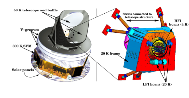
Three cryogenic coolers cool the Planck instruments: a 20 K Hydrogen Sorption Cooler cools the front-end of the LFI and provides a precooling stage for the HFI 4 K Stirling Cooler, which cools the HFI horns and precools the 0.1 K Dilution Cooler, necessary to reach the working temperature of the bolometric detectors. The Sorption Cooler Bhandari et al. (2000), in particular, is a vibration-less cooler that provides 1 W cooling power at 20 K by means of six “compressors” containing a metal hydride that adsorbs and desorbs hydrogen depending on the absolute temperature, thus generating a constant high pressure hydrogen gas flow that expands and liquefies in a Joule Thomson valve.
Planck will orbit around the second lagrangian point (L2) of the Sun-Earth system, at about 1.5 MKm from Earth; this way the Sun and the Earth will always be aligned in the direction of the satellite spin axis with the telescope constantly in shade, thus greatly improving thermal stability. The instruments will scan the sky at 1 rpm with the telescope axis pointing at 85∘ with respect to the spin axis; repointing will occur in discrete steps at the rate of 2.5’ per hour. Following this strategy Planck will cover the whole sky twice in about 14 months, which corresponds to the current baseline mission time.
2 The LFI
The LFI is a radiometer array in the 30-70 GHz range based on ultra-low noise indium phosphide (InP) high-electron-mobility transistors (HEMTs) cryogenically cooled at 20 K, which have shown world-record noise performances over the required 20% bandwidth with very low power dissipation (less that 0.5 W at 20 K) at LFI frequencies.
The particular pseudo-correlation differential design adopted for the LFI radiometers Seiffert et al. (2002) (see Fig. 2) ensures a very low susceptibility of the measured signal to 1/ instabilities of the front-end amplifiers.
In each receiver chain a corrugated dual profiled feed-horn collects and feeds the incoming radiation to an Orthomode Transducer (OMT) that separates the two perpendicularly polarised components. Each feed horn has been custom-designed to optimise the optical response in terms of angular resolution and sidelobe rejection. Every feed-horn in the Planck focal plane has a matched companion pointing in the same direction but with a relative orientation of 45∘ in the sky111Apart for one of the three 44 GHz feeds that could not be optimised because of mechanical constraints. This disposition is optimal for the reconstruction of the CMB polarisation anisotropy. Further details about design and realisation of LFI feed-horns can be found in Villa et al. (2003).
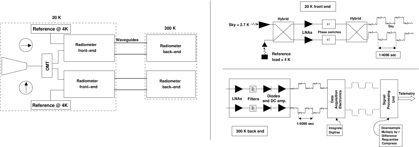
Each arm of the OMT output is connected to a radiometer composed by a cooled front-end (20 K) and a 300 K back-end linked by waveguides. In the baseline design the sky signal coming from each OMT arm is coupled to the reference 4 K signal to the HEMT amplifiers via a 180∘ hybrid. One of the two signals then runs through a switch that applies a phase shift which oscillates between 0 and 180∘ at a frequency of 4096 Hz. A second phase switch is present for symmetry on the second radiometer leg but does not introduce any phase shift in the propagating signal. The signals are then recombined by a second 180∘ hybrid, producing an output which is a sequence of signals alternating at twice the phase switch frequency. In the back-end the RF signals are further amplified, filtered by a low-pass filter and then detected. After detection the sky and reference load signals are integrated, digitised and then differenced after multiplication of the reference load signal by a so-called gain modulation factor , , which has the function to make the sky-load difference as close as possible to zero and cancel at first order 1/ instabilities from the RF radiometer components.
In Tab. 1 we report a summary of the LFI main scientific performances.
| LFI frequency (GHz) | 30 | 44 | 70 |
| Noise per 30’ pixel (K) | 6 | 6 | 6 |
| 1-sec sensitivity (mKs1/2) | 179 | 219 | 310 |
| Number of feeds | 2 | 3 | 6 |
| System Temperature (K) | 7.5 | 12 | 21.5 |
| Effective bandwidth | 20% | 20% | 20% |
| Angular resolution | 30’ | 24’ | 14’ |
| Av. per resolution element (10-6) | |||
| -total intensity- | 2.2 | 2.8 | 4.9 |
| -polarisation- | 3.1 | 3.9 | 6.9 |
3 Systematic error control
The extraordinary sensitivity of Planck instruments calls for consistently tight requirements on systematic errors, especially those that are synchronous with the spacecraft spin period. Spin-synchronous signals, in fact, are virtually indistinguishable from any true sky signal and, therefore, will affect permanently the final LFI maps.
In general we can classify systematic errors into five broad categories:
- main Beam distortions,
-
i.e. deviations of the real main beams from perfect Gaussian beams and differences between beam shapes at the same frequency;
- instrument Intrinsic effects,
-
i.e. systematic effects that arise from non-idealities of the radiometers themselves (e.g. amplifier 1/ noise);
- external Straylight,
-
i.e. signals coming from celestial sources entering the instrument through the antenna side-lobes;
- pointing errors,
-
which depend on the limitations of the satellite attitude control subsystem and on the ability to reconstruct the orientation of the beam using star sensor and instrument data;
- thermal Effects,
-
caused by thermal oscillations on time-scales ranging from less than a minute to more than an hour.
Both the satellite and the instruments are designed to maintain the contamination from astrophysical and instrumental systematic error at the level of few K per pixel in the final maps. This low level of contamination will be guaranteed by the very stable thermal environment in L2, a careful thermal engineering of the thermal interfaces with the intruments and by advanced data analysis procedures that will fully exploit the measurement redundancies provided by the scanning strategy Mennella et al. (2002); Maino et al. (2002). Such data reduction steps are planned to be carried out as part of the LFI Data Processing Centre (DPC) activities Pasian and Sygnet (2002).
References
- Bersanelli et al. (2002) Bersanelli, M., Maino, D., and Mennella, A., Riv. Nuovo Cim., 25, 1–82 (2002).
- Bhandari et al. (2000) Bhandari, P., Bowman, R., Chave, R., et al., Astrophys. Lett. Comm., 37, 227 (2000).
- Seiffert et al. (2002) Seiffert, M., Mennella, A., Burigana, C., et al., Astron. Astrophys., 391, 1185–1197 (2002).
- Villa et al. (2003) Villa, F., Sandri, M., Mandolesi, N., et al., Exp. Astron. (2003), to be published.
- Mennella et al. (2002) Mennella, A., Bersanelli, M., Burigana, C., et al., Astron. Astrophys., 384, 736–742 (2002).
- Maino et al. (2002) Maino, D., Burigana, C., Gòrski, K., et al., Astron. Astrophys., 387, 356–365 (2002).
- Pasian and Sygnet (2002) Pasian, F., and Sygnet, J. F., SPIE, 4847, 25–34 (2002).