The optical system of the H.E.S.S. imaging atmospheric Cherenkov
telescopes
Part I: layout and components of the system
Abstract
H.E.S.S. – the High Energy Stereoscopic System – is a new system of large imaging atmospheric Cherenkov telescopes, with about 100 m2 mirror area for each of four telescopes, and photomultiplier cameras with a large field of view () and small pixels (). The dish and reflector are designed to provide good imaging properties over the full field of view, combined with mechanical stability. The paper describes the design criteria and specifications of the system, and the individual components – dish, mirrors, and Winston cones – as well as their characteristics. The optical performance of the telescope as a whole is the subject of a companion paper.
, , , , , , , , , , , , , , , , , , , ,
1 Introduction
Imaging atmospheric Cherenkov telescopes (IACTs) have emerged as the prime tool for ground-based gamma-ray astrophysics in the VHE (very high energy) regime [1]. IACTs detect gamma-ray induced air showers via their emission of Cherenkov light. The shower is imaged either by a single telescope or simultaneously by several telescopes, which provide multiple views of an air shower and which enable the stereoscopic reconstruction of the shower geometry, resulting in improved angular resolution, energy resolution, and background suppression. With their large effective detection areas of typically 50,000 m2 near threshold and a few 100,000 m2 at very high energy, IACTs are sensitive to very small photon fluxes. Observations with IACTs such as the Whipple [2], CANGAROO [3], Durham[4] and CAT [5] telescopes and with the HEGRA telescope system [6] have established about a dozen cosmic sources of TeV gamma rays, both galactic and extragalactic [1]. The faintest source has a gamma-ray flux around /cm2s above 1 TeV, corresponding to about 3% of the flux from the Crab Nebula, which is often used as a “standard candle”.
While the results obtained in the last years have provided a great deal of information both about the acceleration mechanisms of high-energy particles in astrophysical objects and about the propagation and interactions of VHE photons, it is obvious that the sensitivity of current-generation instruments is marginal in the sense that (a) only the strongest – and often atypical – sources of each class are observable, and that (b) the number of objects in each source class is so small, that it is hard to decide which of the observed spectral features represent generic properties of the acceleration mechanism, and which are simply consequences of the specific initial conditions or of the environment of a given source.
As a result, a number of next-generation IACTs and IACT systems are under construction; as examples we mention the High Energy Stereoscopic System (H.E.S.S.) with initially four telescopes located in Namibia [7, 8], the CANGAROO four-telescope system in Australia [9], the VERITAS project consisting of seven telescopes in the USA [10], and the single large MAGIC telescope on the Canary Island of La Palma [11]. Common goals of these instruments are to lower the threshold for the detection of gamma-ray induced air showers to 100 GeV or below, and to improve the sensitivity at higher energies by about one order of magnitude. Reflector areas range from about 50 m2 for each of the CANGAROO telescopes to more than 230 m2 for the MAGIC dish.
All of these Cherenkov telescopes use optical systems consisting of large tessellated reflectors, focusing the Cherenkov light onto photon detectors made of bundled photomultiplier tubes (PMTs) to resolve the image of the air shower. With a characteristic size of air shower images of to , fields of view of the cameras range from to ; at the lower limit, the camera is barely big enough to contain shower images from a source located at the center of the field of view, whereas a large field of view allows one to map sources with a modest spatial extension, such as galactic Supernova remnants. The size of individual camera pixels (usually 0.1∘ to 0.2∘) is matched to the scale of coarse features of the shower image. While an even smaller pixel size would provide further improvements in performance, a fine segmentation of the photon detector quickly results in a very large number of pixels and in prohibitive costs.
Task of the optical system of IACTs is to collect the Cherenkov light and to focus it onto the photocathodes of the PMTs. The transmission of the optical system should be close to unity, to make optimum use of the reflector area, and the point spread function should ideally be smaller than the pixel size over the entire field of view. Given that data on a single source are often accumulated over 100 and more hours spread over several months or even years, long-term stability of the optical system is of crucial importance. While the imaging performance of IACTs is modest compared to normal astronomical telescopes, the cost-effective design of the dish and reflector of large Cherenkov telescopes is non-trivial and represents a key ingredient for the quality of the observations and the success of the instrument. The design and performance of optical systems of Cherenkov telescopes are discussed, e.g., in [12] (Whipple), [13] (HEGRA) and [14] (CANGAROO).
With the goal both to present the technical solutions for the various elements and to provide a reference for future publications of physics results from H.E.S.S., this paper summarizes the design, implementation, and the components of the optical system of the H.E.S.S. telescopes. The following chapters describe the general design considerations, the reflector facets, the Winston cone light collectors in front of the PMTs, and the mechanical layout of the dish and of the mirror supports. The mirror alignment procedure and the optical performance of the telescope are the subject of a second paper.
2 Overview and design considerations
This section outlines the general design considerations of the optical system of the H.E.S.S. telescopes and the specifications derived for its various components.
2.1 The H.E.S.S. telescopes
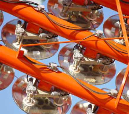
Basic design criteria of the H.E.S.S. telescopes [7, 8] (Fig. 1) were a reflector area of about 100 m2, a camera field of view of diameter and a pixel size of , resulting in 960 pixels in each camera. Given a typical yield of Cherenkov photons of about 100/m2 TeV (in the 300 to 600 nm range) at about 2 km height a.s.l., combined with reflectivities of the mirror of 80% to 90%, a similar transmission for the light-collection funnels in front of the photomultiplier tubes, and an average photomultiplier quantum efficiency around 15%, this reflector area guarantees a threshold around 100 GeV. At this energy, images will contain around 100 photoelectrons, and some detection capabilities should be provided down to 50 GeV and below. The camera field of view of allows one to observe sources with an angular extension of a few degrees, and provides improved detection capabilities for distant high-energy showers. The pixel size is matched to the size of image structures and results in a still manageable count rate induced by night-sky photons – about 100 MHz per pixel [15]. PMT signals are recorded by 1 GHz analog waveform recorders based on the ARS ASIC; the entire electronics for triggering and signal readout is contained in the approx. 900 kg camera body [16].
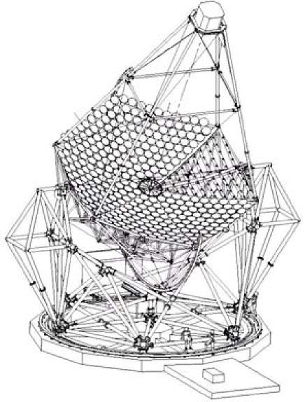
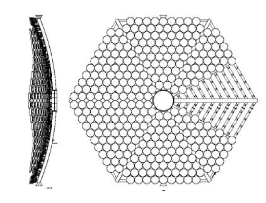
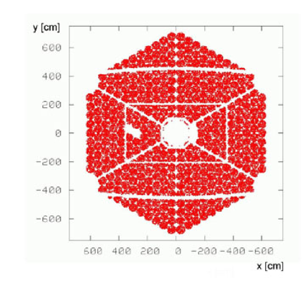
The reflector is segmented into 380 round mirror facets of 60 cm diameter, supported by a steel spaceframe. The arrangement of mirrors is illustrated in Fig. 2. Motorized mirror support units are used for the remote alignment of the mirror facets, under the control of a CCD camera at the center of the dish, viewing the photomultiplier camera. The alignment algorithm is based on star images viewed on the closed camera lid. The photomultiplier camera is supported by four arms at the focal distance of 15 m; combined with a characteristic dish size of 13 m the telescopes have .
The dish with the camera arms is mounted in alt-az fashion in a rotating baseframe, supported at the ends of the elevation axis by two towers. The baseframe rotates around a central bearing, on six wheels running on a 13.6 m diameter rail. Both in azimuth and elevation, the telescope is driven by friction drives acting on special 15.0 m diameter drive rails. The large lever arm reduces the drive forces and the requirements on the reduction gears. In both axes, the telescope slews at /min. The position is sensed by shaft encoders attached at the central bearing and at one end of the elevation axis, with a digital step size of . A guide telescope mounted off-axis on the dish and equipped with a CCD camera should provide arc-second pointing resolution.
2.2 Optics layout
For cost reasons, the H.E.S.S. telescopes use – like all other large IACTs – a segmented reflector composed of many individual mirror facets. The facets are manufactured as spherical mirrors. The possible options in the optics layout concern primarily the arrangement of the mirror facets and the choice of the focal length for a given reflector size. In addition, there is some freedom concerning the size and shape of mirror facets.
Classical arrangements of Cherenkov telescope reflectors follow either the Davies-Cotton layout [17], or a parabolic layout. In the Davies-Cotton layout, generated originally with solar concentrators in mind, all reflector facets have the same focal length , identical to the focal length of the telescope as a whole. The facets are arranged on a sphere of radius . In a parabolic layout, mirrors are arranged on a paraboloid , and the focal length of the (usually spherical) mirror facets varies with the distance from the optical axis. While this adds a certain complication to the manufacturing process, the overhead is acceptable in particular when large numbers of mirror facets of each focal length need to be manufactured. With small and perfect mirror facets, both approaches provide an essentially point-like focus for rays parallel to the optical axis. Both suffer from significant aberrations for light incident at an angle to the optical axis, the parabolic layout to a slightly larger extent than the Davies-Cotton layout. Standard optics theory predicts that the aberrations should increase linearly with the angle to the optical axis, and with the inverse square of the ratio of focal length to reflector diameter, . Another criterion is the time dispersion introduced by the reflector, which should not exceed the intrinsic spread of the Cherenkov wavefront of a few nanoseconds. Parabolic reflectors are isochronous – apart from the minute effects introduced by the fact the individual mirror facets are usually spherical rather than parabolic – whereas the Davies-Cotton layout results in a spread of photon arrival times at the camera; a plane incident wavefront results in photons spread uniformly over an interval , with a rms width .
The basic imaging characteristics are illustrated in Fig. 3(a)-(c), which are based on ray-tracing simulations [18, 19, 20] of different reflector geometries.


The reflectors of the H.E.S.S. telescopes follow a Davies-Cotton layout. The time dispersion of such a reflector of ns rms is still considered uncritical, since it is of the same order as the intrinsic time spread of shower photons. The H.E.S.S. signal recording electronics is designed to integrate photomultiplier signals over 16 ns so that signal are always fully contained, and the influence of the additional time smearing due to the mirror geometry is marginal. The trigger electronics with its higher bandwidth would benefit from a parabolic dish, providing slightly lower thresholds. On the other hand, off-axis imaging of a Davies-Cotton mirror is slightly better (about 20% in the spot size, see Fig. 3(b)) for the Davies-Cotton layout, which is important since one of the design goals was the uniform response over the large field of view, required for observations of extended sources. While the tradeoff between the two variants is fairly balanced, the improved imaging led us to adopt the Davies-Cotton layout.
The choice of the ratio is a compromise between the off-axis imaging quality and the increased cost, lower resonant frequencies and mechanical complications caused by the need to support the camera at a larger distance from the dish. Under these boundary conditions, was adopted; with this choice, the (rms) optical aberrations at off axis roughly equal the (rms) pixel size.
The simulations shown in Fig. 3(a),(b) assume that the individual mirror facets are perfect (spherical) mirrors. If the individual facets are characterized by a point spread function of width 111Here and in the following, denotes the rms width of the distribution after projection on one coordinate axis. A corresponding two-dimensional Gaussian point spread function is then given by ; the radii enclosing 68% and 80% of the light are given by and , resp., the overall point spread function should basically be given by a quadratic sum of the facet point spread function and the aberrations caused by the dish geometry. The ray-tracing simulations of Fig. 3(c) confirm that this is the case. A facet point spread function of 0.3 mrad rms will hardly be noticeably except right on-axis; a point spread function up to about 0.5 mrad rms would be tolerable, in comparison to the pixel size and the off-axis aberrations. After discussions with manufacturers of mirror facets, the specification was adopted that a mirror facet should image 80% of the light within a circle of 1 mrad diameter; for a Gaussian point spread function, this is equivalent to a rms width of 0.28 mrad. This specification is well below the critical performance, and was accepted by the manufacturers to be reachable without significant extra cost. Indeed, the quality control measurements discussed below show that most mirrors pass this specification by a significant margin.
In addition to their quality, the size of the individual mirror facets influences the optical performance; large (spherical) facets will introduce additional optical errors. For the 60 cm facets used in H.E.S.S. – primarily for cost reasons, see below – the resulting degradation is minimal.
Note that in all examples shown in Fig. 3, the mirror facets are aligned for optimal on-axis imaging at a focal length . Given the goal of a uniform imaging over a large field of view, one might ask if other alignment schemes are possible which improve the off-axis response at the expense of on-axis imaging, or if mirror arrangements other than parabolic or Davies-Cotton provide improved performance over the whole field of view. Indeed, modest improvements of the off-axis response can be obtained by slightly displacing the focal plane towards the reflector, by using a curved focal plane, or by modifying the Davies-Cotton layout by moving the outer mirrors closer to the focal plane, with a corresponding change in their focal lengths [8]. However, in all cases studied the improvements were small, and did not warrant the additional complications or the degradation of the on-axis response.
As an additional option, systems with secondary reflectors were considered, which provide a partial compensation of aberrations. However, apart from the non-trivial construction and alignment of the secondary reflector - which would also have to be realized as a segmented mirror – such designs resulted in large effective focal lengths and hence in much larger cameras (for a given field of view), with significant implications on the cost and performance of the photomultiplier tubes.
2.3 System specifications and error budget
The effective optical quality of the telescope is determined by a number of factors, in particular
-
1.
the aberrations inherent in the optics layout,
-
2.
the optical quality of the individual mirror facets,
-
3.
the tolerances in the design and fabrication of the dish, i.e., the precision with which the mirror facets are positioned, relative to their nominal locations,
-
4.
the quality of the alignment of the facets, and
-
5.
the deformations of the support structure under the influence of wind loads, gravity load, temperature variations etc.
A pixel of the H.E.S.S. cameras covers a rms projected angular range of about 0.7 mrad. The point spread function of the reflector should not exceed this width significantly, and ideally be smaller, in order to make full use of the camera granularity. In the design of the H.E.S.S. telescopes, roughly equal contributions of optical errors were allocated to the mirror facets (0.28 mrad rms, in each projection), to the deformation of the support structure under gravity and wind loads, temperature variations etc., and to the precision of the mirror supports and of the mirror alignment. A limit of 0.28 mrad rms on the influence of the carrier structure means that the structure has to be stable to 0.14 mrad rms, since errors are doubled due to the reflection of light. The same is true for the mirror supports and the mirror alignment. Compared to the angular alignment of mirror facets, their positioning turns out to be completely uncritical. Mirror facets can be displaced along the optical axis by 10 cm or more without significant impact. If all components perform at the limit, the resulting spot size on axis is about 0.5 mrad rms.
3 Mirror facets
In the initial stages of the design, a number of different mirror options were explored, including
-
•
diamond-turned aluminum mirrors in the 50-60 cm diameter range,
-
•
aluminized ground-glass mirrors in the 50-120 cm diameter range,
-
•
mirrors consisting of a carbon fiber substrate covered by a reflecting foil, and
-
•
membrane mirrors consisting of a steel membrane formed by slight underpressure, covered with thin-glass mirrors or mirror foils, in the 120-240 cm diameter range [21].
With the test setup [22] described below, glass mirrors from three different manufacturers were tested, aluminum mirrors from two suppliers, and a prototype membrane mirror built in-house. While the H.E.S.S. Letter of Intent [8] still gave aluminum mirrors as the baseline option, the tests showed that the glass mirrors were consistently superior to the aluminum mirrors available to us at the time, in particular in terms of specular reflectivity. Concerning the spot sizes, the aluminum mirrors were marginally acceptable. The membrane mirror showed poor image quality; this option was abandoned because of the anticipated long time scale for further development.
Since the cost of glass mirrors was at the same level or below that of aluminum mirrors, since weight was not of primary concern (and in any case not much different between a glass mirror and a solid aluminum mirror), and since glass mirrors had demonstrated their long-term stability in the HEGRA and CAT telescopes, glass mirrors were chosen.
Among various mirrors sizes quoted, there was a clear cost optimum per unit mirror area for facet diameters around 50 cm to 60 cm. Concerning facet shape, square and hexagonal mirror facets provide complete coverage of the mirror area, whereas round mirror facets will cause a 10% loss for the same dish diameter. However, hexagonal or square mirrors would have to be cut out of round mirrors, at significantly increased cost per area. Therefore, round mirrors were chosen.
The resulting specifications for the mirror facets are given in Table 1.
| Material | Aluminized optical glass, thickness mm |
|---|---|
| Protection | Quartz coating for outdoor use |
| Diameter of mirror | 600 1 mm |
| Diameter of reflecting surface | mm |
| Mounting | Glued to support unit at three points |
| Focal length | 15.00 0.25 m |
| Point spread function | 80% of light in 1 mrad diameter |
| Specular reflectivity | at least 80% between 300 and 600 nm |
3.1 Mirror test setup
In order to characterize the imaging properties and reflectivity of a mirror, the mirror is placed at twice the nominal focal distance (30.00 m) from a light source equipped with a 3 mm diameter diaphragm. The light source illuminates the mirror uniformly; over the 60 cm diameter, variations in intensity are below 6%. The mirror is oriented such that the light source is slightly off the optical axis, and a computer-controlled 3-axis positioner carrying a photo diode is used to scan the resulting image. The resolution of the scan, about 0.33 mrad FWHM, is determined by a 10 mm diaphragm in front of the scanning diode. Scans are carried out with a step size of 5 mm, equivalent to 0.17 mrad. Fig. 4 shows two examples of scanned images. Integrating outward from the center of gravity of the image, the diameter of a circle enclosing 80% of the reflected light is determined and is used to characterize the mirror.
In initial tests, images were scanned at different distances from the mirror in order to determine the optical focus and the focal length; in the later series tests, only the image at the nominal focal length is scanned. The measured spot width combines both focusing imperfections of the mirror and deviations from the nominal focal length; only this quantity is relevant for our application.


In order to calibrate the light source, the scanning diode is moved into the beam of the light source, such that it covers roughly the same solid angle as the mirror, and the light flux per solid angle is measured, given the known distance to the source and the active area of the diode. By integrating the reflected light over the scanned image and comparing its intensity with the light incident on the mirror, the absolute specular reflectivity is determined. The amount of light incident on the mirror is determined from the measured flux per solid angle and the distance, assuming a 60 cm diameter mirror. If the aluminized area of a mirror is smaller – specifications require at least 59.8 cm – this will result in a slightly lower average reflectivity. During the calibration and the measurements, a second photo diode is placed off-axis in front of the light source, such that it does not obscure the mirror, but is still in the region of uniform illumination. This second diode is used to correct intensity variations of the light source during measurements.
A computer-controlled filter wheel in front of the scanning diode enables wavelength-selective measurements; four filters with 300, 400, 470 and 600 nm center wavelength and a bandwidth of about 10 nm are employed. We note that this measurement determines the specular reflectivity under realistic conditions, rather than the (frequently quoted by manufacturers, but irrelevant) total reflectivity including diffuse reflection.
The accuracy of the reflectivity measurement was checked by cross calibration with other methods and by repeated measurements of reference mirrors over longer periods. We estimate the systematic errors in reflectivity at 2.8% at 300 nm, and about 2% at 400, 470 and 600 nm.
3.2 Mirror characteristics
Two suppliers were chosen for the mirrors of the H.E.S.S. telescopes, COMPAS in Turnov (Czech Republic) for 1150 mirrors and Galaktica in Yerevan (Armenia) for 600 mirrors. Each mirror delivered was inspected visually for scratches or mechanical defects, and the mirror diameter and the diameter of the reflecting surface were measured. Finally, the reflectivity and spot size were determined at the four wavelengths222The first batches were measured at only two wavelengths, 310 and 470 nm.. At the time of this writing, all mirrors have been delivered, and about 90% of them have been measured [23, 24].
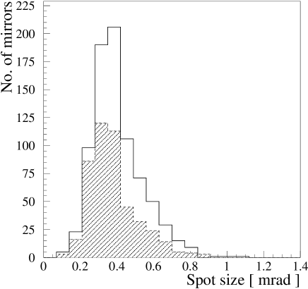
Fig. 5 shows the distribution of measured spot sizes for the COMPAS and the Galaktica mirrors, at 400 nm. Shown are all mirrors, including those later rejected because of insufficient reflectivity. Most mirrors show a spot size around or below 0.5 mrad (diameter for 80% containment), a factor 2 below specifications.
The spot sizes measured for a given mirror at different wavelengths are highly correlated (Fig. 6), as expected since the spot size is determined by the mechanical quality of the mirror shape and surface.

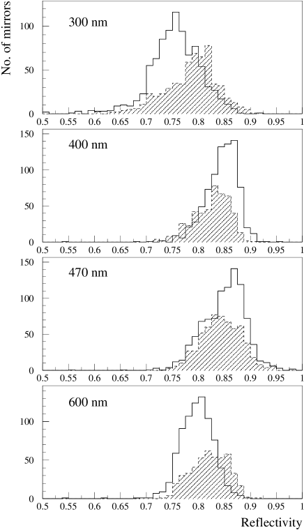
Whereas the measured spot sizes gave little reason to reject mirrors, reflectivities were a reason of concern. Figs. 7(a) to (d) show the reflectivities measured at the four wavelengths, for both types of mirrors. A significant number of mirrors fall below the initial 80% reflectivity criterion, in particular at 300 nm. In order to achieve an acceptable yield, and taking into account the uncertainties in the measurement, rejection criteria were lowered to at 300 nm and at any of the larger wavelengths. Reflectivities measured at different wavelengths show some correlation between neighboring wavelength bands. Very little correlation is observed, however, between the values for 300 nm and 600 nm.
The reflectivity of the COMPAS mirrors was checked at the factory with a commercial reflectometer; Fig. 8 illustrates some of the results for fairly typical mirrors. The measured reflectivities are systematically higher by about 5% than the typical values measured in our laboratory; the reason is not fully understood, but may be related to the fact that in the measurements at the factory only selected spots on the mirror are measured, whereas in our measurements the whole surface is averaged. Furthermore, a slightly diffuse halo is ignored in our scans of the spot at , but may partly be counted in the reflectometer.
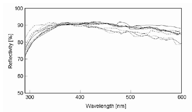
Of the mirrors delivered, 4% and 12% of COMPAS and Galaktica mirrors, respectively, were rejected because of mechanical defects or other problems found in the initial inspection. All measured spot sizes were considered acceptable. Because of insufficient reflectivity, 20% and 16%, respectively, were returned for recoating after the measurements. Fig. 9 shows the average reflectivity of the accepted mirrors passing all tests.

3.3 Long-term stability of mirrors
Experience with very similar quartz coated glass mirrors has also been reported from HEGRA [25]; there, a loss of reflectivity of 3-4% per year is quoted, which means that mirrors have to be recoated at least every five years. H.E.S.S. mirrors were exposed for about two years both in Namibia (6 mirrors) and in Heidelberg (2 mirrors). The observed deterioration was consistent with the HEGRA results, although the number of mirrors was too small to draw a definitive conclusion, also given the systematic errors in the reflectivity measurements, where over time different instruments were employed.
4 Winston cones
Most modern Cherenkov telescopes use non-imaging light concentrators – i.e., funnels of some type – in front of the photomultiplier tubes. These concentrators serve a dual purpose:
-
•
They avoid dead areas due to insensitive areas at the outer edges of the PMT cathodes and due to the support structure in between PMTs.
-
•
They limit the solid angle viewed by the PMT and reduce noise due to stray light from the ground, shining past the reflector, or from the sky in case the telescope is observing at low elevations.
The angular acceptance of a light concentrator and the ratio of its input and output apertures are closely related. According to Liouville’s Theorem, the phase space volume filled by light, is conserved; here we have assumed uniform illumination over a diameter and a range of angles up to . Winston cones [26] are a special design of concentrator, optimized for a sharp angular cutoff. For an ideal Winston cone with entrance diameter and exit diameter , the cutoff angle is given by .
4.1 Optimization and layout of the Winston cones
Boundary conditions for the optimization of the Winston cone light concentrators of the H.E.S.S. camera were [27]:
-
•
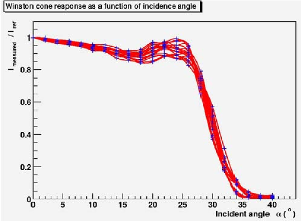
the angular cutoff coincides with the outer edge of the dish (Fig. 10),
-
•
the input area has a hexagonal shape in order to cover the focal plane with minimal losses,
-
•
the output area must not exceed the sensitive area of the PMT cathode (Fig. 11), and
-
•
the cone surfaces must provide high reflectivity.
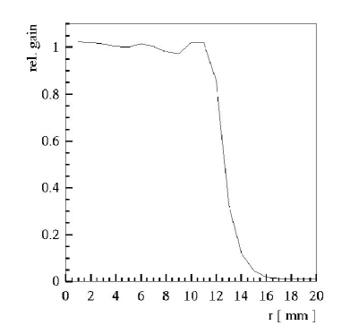
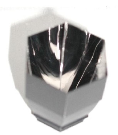
On the basis of ray-tracing simulations, a cone geometry with a hexagonal input aperture of 41 mm width (flat-to-flat), a hexagonal output aperture of 21.5 mm width, and a length of 53 mm was adopted. The Winston cones (Fig. 12) are made of extruded plastic, composed of two halves, and their inner sides are aluminized and covered with a thin quartz coating. The individual cones are locked in a carrier plate, which defines their locations with high precision. With a thickness of the cone walls at the entrance of the cone of 0.5 mm, the typical dead space between adjacent cones is about 1 mm, equivalent to 5 % of the area.
4.2 Measurements
The transmission of all Winston cones was measured in a custom-built setup. Fig. 13 illustrates the transmission of a typical cone as a function of the angle of incidence. The cones exhibit a fairly sharp cutoff at about , coincident with the angle under which the camera views the edge of the dish (Fig. 10). The absolute transmission of all Winson cones was measured using a back-lit hexagonal diffusive screen as a light source and a XP2020 PMT as photon detector; the screen covers the same range of angles as the mirrors on the telescope. The PMT current was then determined both with the Winston cone and with a hexagonal mask, and normalized to the entrance area of the cone, resp. to the area of the mask. The transmission is defined as the ratio with and without cone. Average transmission values for the cones used in the cameras are 0.70, 0.67, 0.79, 0.80, and 0.77 for wavelengths of 300 nm, 350 nm, 400 nm, 450 nm and 500 nm, respectively. The rms scatter of transmission values among different cones is about 0.02, with strong correlations between different wavelengths. Slightly over 10% of the produced cones were rejected because of poor transmission.
5 Dish and mirror support units
The full optical performance of the telescope can only be realized if the support structure is rigid enough that the relative positions and orientations of the mirrors are maintained under operating conditions, such as variable elevation and wind. The H.E.S.S. telescopes rely on a stiff steel structure to hold the mirrors, and on motorized mirror support units to provide the fine adjustments. The mechanics is designed such that the mirrors should stay aligned over long periods (many months) without a need for realignment.
5.1 The telescope dish
The dish is constructed from steel, consisting of a shell made of twelve strong (260 by 260 mm2) radial beams dividing the dish into 12 sectors (Figs. 1,2). In each sector, 10 mirror support tubes (159 mm diameter) carry mounting brackets to attach the mirrors, via their mirror support units. A spaceframe made of 83 mm diameter steel tubes provides depth and stiffness for the structure. Additional stiffness is provided by tensioning the dish along its elevation axis with a force of approximately 100 kN, applied via the two support towers and the baseframe. The total mass of dish structure is 23.4 t, including the mirror mounting brackets. The mirror support units and mirrors add 7.6 t; additional masses include 3.25 t of the camera support, 2.46 t of the elevation drive rail and 0.8 t of counterweights required to balance the dish.
The telescope structure was designed by SBP333Schlaich Bergermann und Partner, Consulting Engineers, Stuttgart and produced by NEC-Stahl444Namibia Engineering Corporation, NEC-Stahl, Okahandija based on production drawings by SCE555Seelenbinder Consulting Engineers, Windhoek.
We note that the spherical shell required for an exact Davies-Cotton layout is approximated by straight mirror support tubes in each of the twelve dish sectors. The geometry of the radial support beams, with a curvature radius of 15.86 m, was optimized to minimize the deviations from an exact Davies-Cotton layout. In the worst cases, mirrors are displaced by about 8 cm in the direction (parallel to the optical axis) from their nominal positions. Such a displacement is tolerable due to the relatively small size of the mirror facets; if the focal plane is displaced by 15 cm, the spot of an otherwise ideal mirror of 60 cm diameter will grow to 0.6 cm diameter, or 0.4 mrad, well below the pixel size.
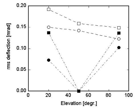
Extensive FEM simulations of the dish were carried out by SBP to evaluate and optimize the stability of the dish, under gravity load, wind loads, and under the influence of deformations of the baseframe induced by slight unevenness of the azimuthal rail. The predicted gravity-induced deformations of the dish are illustrated in Fig. 14. Two sets of points are given, one corresponding to the total deflection of mirrors under the influence of gravity at various elevations, and one assuming that mirror facets are aligned at elevation, such that only the deflection relative to the alignment position matters. Compared to these gravity loads, the influence of wind loads etc. is small.
The main specifications of mount and dish are summarized in Table 2.
| Dish | |
|---|---|
| Number and type of mirrors | about 380 60 cm mirrors |
| weight incl. support 20 kg each | |
| Mirror spacing | 62 cm center-to-center |
| Mechanical tolerances of dish structure | 5 mm |
| Tolerance on orientation of mirror mounting brackets | |
| Variation of mirror orientation with elevation | mrad rms in each projection |
| for to elevation | |
| Mount | |
| Turning range in azimuth of mount | |
| Elevation range of mount | to |
| Slewing speed in azimuth and elevation | /min |
| Positioning accuracy | |
| Max. wind speed during operation | 50 km/h |
| Max. wind speed | 160 km/h |
A final point of discussion was the coloring scheme of the mount and dish structure. There are two conflicting requirements. To reduce heating of the structure during daytime, it is best painted white. On the other hand, for nighttime observations a dark color is preferred, since it (a) minimizes stray light – part of the telescope structure is visible from the camera, e.g. in between mirrors – and since it (b) helps to reach thermal equilibrium more quickly. Most of the insolation during daytime is at long wavelengths, in the red and IR, whereas the PMTs of the camera are sensitive mainly to blue light. A red color provides a good compromise, since it reflects at long wavelengths and absorbs in the blue. Characteristics of different colors were studied by measuring the temperature increase when structures were exposed to sunlight, and by evaluating the reflectivity as a function of wavelength [28]. Following objective criteria, a bright red/pink color would be optimal. As a compromise between these criteria and the subjective impression, a slightly darker red tone was adopted.
5.2 The mirror support units
Purpose of the mirror support units is (a) to attach the mirrors firmly to the dish structure, and (b) to enable the remote adjustment of mirrors. In order to prevent damage to, or deformations of the mirrors, the mirror support system must not impose significant stress onto the mirror, and must allow for differential thermal expansion of the mirror and its support. The key specifications for the mirror support units are summarized in Table 3.
| Mirror support units | |
|---|---|
| Load | Mirror weight 10 - 15 kp, wind load negligible during normal operation |
| Peak wind load 30 kp | |
| Support | Must not overconstrain the mirror, or induce stress |
| Stability | Mirror orientation stable to 0.1 mrad (rms) under operating conditions |
| Adjustment range | Mirror orientation adjustable within ( 17 mrad) |
| Adjustment precision | 0.1 mrad maximum deviation, relative to last position; |
| only relative positioning required | |
| Speed | at least /min. |
| Environmental conditions | Temperatures to ( to during adjustments) |
| Humidity 0% to 100% ; high UV radiation; dust and sand | |
The solution adopted is illustrated in Fig. 15. A mirror unit consists of a support triangle carrying one fixed mirror support point and two motor-driven actuators. The mirror is attached at these three points using steel pads glued to the back of the mirror. The whole unit is preassembled and then with three screws attached to the mounting bracket welded to the mirror support tube of the dish. The mounting brackets have a machined surface and are pre-aligned before the welding, to a precision of , so that the support unit provides only the final alignment within a limited range.
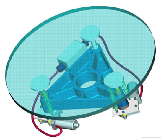
The basic support triangle underwent several design iterations, until finally a 5 cm thick cast-aluminum structure proved to be stable enough. Under the load of the mirror, the triangle (and the mounting bracket) is deformed by about 6 m, equivalent to an angular deflection of 0.02 mrad.
The actuators are based on automotive products used to drive car windows666Bosch, Type 0 130 821 708/709. A motor unit includes the drive motor, two Hall sensors shifted by sensing the motor revolutions and providing four TTL signals per turn, and a 55:1 worm gear with a nominal speed at the exit of 100 rpm and a torque of 1.5 Nm, increasing to 6 Nm at lower speeds. The motor is directly coupled to a 12 mm threaded bolt, driving the actuator shaft by 0.75 mm per revolution. The total range of an actuator is 30 mm; one count of the Hall sensor corresponds to a step size of 3.4 m, or about 0.013 mrad tilt of the mirror.
The mirror is supported in three points, using 8 cm diameter steel pads glued to the back of the mirror. To reduce stress, a flexible 3 mm glue layer777TEROSTAT 8590 (black) is used; a primer888TEROSTAT PPRIMER 8511 provides optimum contact to the glass and a sealant999TEROSTAT DICHTSTOFF M935 (white) around the circumference protects the glue from UV solar radiation.
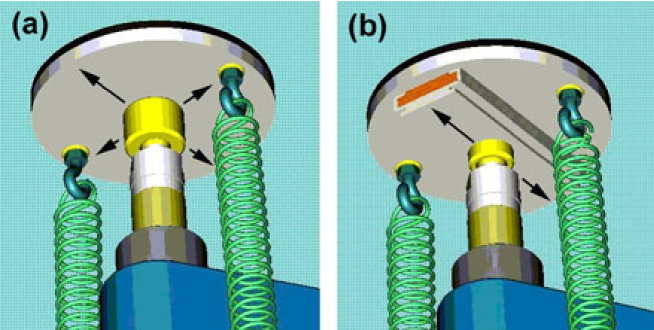
Of the three support points, one – the fixed point – is equipped with a spherical joint. One of the actuator heads (Fig. 16(b)) is attached to the steel pad via a spherical joint and a one-dimensional slider101010IGUS Drylin N. The second head (Fig. 16(a)) can slide in two directions on the steel pad, with a plastic pad 111111IGUS iglidur G added to reduce friction. Springs at each support point pull the steel pads towards the support, hold the mirror in place and eliminate play. This arrangement, where all support points can adjust their orientation, one is fixed, one moves in one direction and one moves in two directions in the plane of the mirror, fully constrains the position and orientation of the mirror, yet allows the mirror to expand and avoids stress on the mirror when moved.
The performance and reliability of the mirror support units was tested extensively by cycling the temperature over extended periods between and , and the humidity between 10% and 80%. At the same time, the units where exposed to UV radiation from a 1 kW metal halid lamp, simulating the conditions in Namibia. Of particular concern was the behavior of the thick glue layer; it shows a constant, linear m/∘C expansion, which should not influence the mirror pointing. We verified that image spots do not vary significantly when a mirror is moved, which would be a sign of stress-induced deformations.
5.3 The mirror control system
A special control system was designed to control all actuator motors of a telescope [31]. The dish is divided into twelve segments with up to 32 mirror facets (64 motors) each, and one branch cable runs along the mirrors of one segment to connect them to the control system. For each mirror, a short cable branches off the main branch cable and is plugged into a small relay box attached to the mirror support triangle (see Fig. 17).
Within a branch, one motor out of 64 is selected using 2 8 wires which form an address matrix, implying that only one motor can be driven at a time. The twelve branch cables of a telescope are connected to branch driver boards located in an electronics hut on the baseframe. The branch driver boards provide all necessary power and signals, and are controlled via a VME bus interface. The Hall signals of the selected motor are fed into a special decoder 121212Agilent, HCTL-2020 which derives information about the direction of movement and the number of Hall counts, i.e. the distance of actuator travel. It implements a set of signal filters and consistency checks to avoid miscounts. Note that the Hall sensors do not allow one to determine the absolute position of an actuator. This restriction can be addressed by using one of the actuator stops as an internal position reference, and by using the control system to turn off the motor after a predetermined number of counts, so that a precise relative positioning is achieved. In order to position an actuator, usually 2-3 iterations are required, since – depending on its speed and load – the motor may keep turning for a few Hall counts after the drive voltage is switched off. To simplify the system, the actuators are not equipped with end switches. Instead, springs stop the actuator at the ends of its range, and the control system detects the missing Hall counts and shuts off the actuator motor.
5.4 Tests of the mirror alignment system
The actuators and control systems were tested extensively. Tests of the control electronics showed that no miscounts of Hall signals occur, implying that the (iterative) positioning of actuators can be performed with a precision of one Hall count, or about 3m [32]. In tests where the reflected spot of a mirror was monitored by a CCD camera, a rms positioning accuracy of the mirror of 0.0086 mrad was achieved consistently (Fig. 18); this value is only slightly larger than the expected optimum of 0.0075 mrad, based on the finite step size of the actuator, and is absolutely minute compared to the mirror spot size.

6 Effective reflector area
An essential performance characteristic of the telescope and input for simulations is the effective reflector area. It is governed by the following factors [19]:
-
•
the number of mirror facets on a telescope is 380 (the dish can hold 382; two mirrors are omitted to provide space for the optical guide telescope),
-
•
in particular the outer mirror facets are inclined (by up to ) with respect to the plane of incident light, reducing the effective reflector area by 1.1% in comparison to 380 times the facet area,
-
•
the camera arms and their bracing struts shadow about 5-6% of the incident light, and
-
•
some of the bracing struts in addition shadow reflected light, causing an additional 5-6% reduction in light yield.
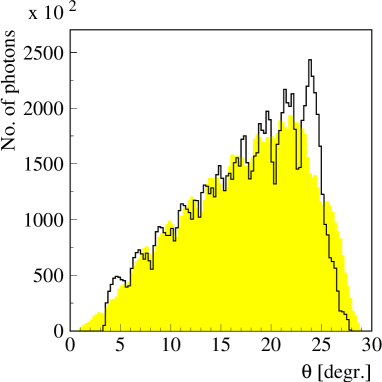
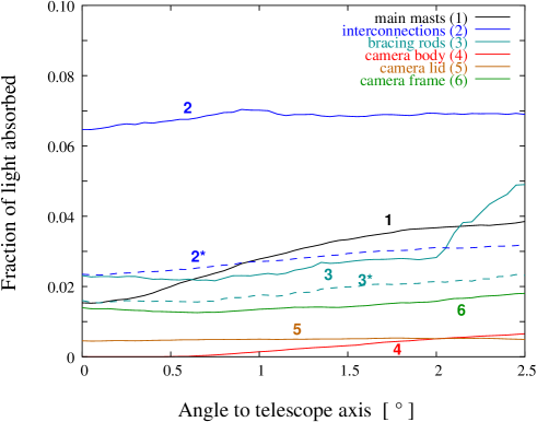
Fig. 19 shows the results of a ray-tracing simulation illustrating which parts of the reflector are shadowed. The exact fraction of light lost depends somewhat on the angle of incidence relative to the optical axis, and also on the azimuth, and varies between 10% on-axis and about 12% at the edge of the field of view, see Fig. 20. The resulting effective reflector area of a H.E.S.S. telescope varies over the field of view between 93.4 m2 and 95.3 m2
7 Summary
The H.E.S.S. optical system is based on a segmented reflector with and a reflector area of 107 m2; the 380 spherical mirror facets have identical focal lengths of 15 m and are arranged in a Davies-Cotton layout. Shadowing due to the camera arms reduces the effective reflector area to about 95 m2, depending slightly on the angle of incidence. The mirror facets are ground glass mirrors, aluminized and quartz coated. The mirror facets were measured individually and typically concentrate 80% of the reflected light within a circle of about 0.4 mrad diameter, well below specifications. The average reflectivity in the relevant wavelength region is 80% to 85%. Including optical aberrations, the system should provide a point spread function which is on the optical axis significantly smaller than the pixel size of , and which is comparable to the pixel size near the edge of the field of view of the PMT camera. Winston cone light concentrators added in front of the PMT pixels serve both to improve light collection, and to limit the field of view to the size of the reflector to reduce albedo from the ground.
The mirror facets are carried by motorized support units, to allow remote adjustments of the mirror orientation. In the design of the dish, mechanical stiffness and minimal deformations under gravity load were emphasized to maintain a good point spread function over a wide range of elevations.
The mirror alignment and the resulting measured point spread functions are covered in a companion paper.
Acknowledgements
A large number of persons have, at the technical level, contributed to the design, construction, and commissioning of the telescopes. We would like to express our thanks to the technicians and engineers from the participating institutes for their devoted engagement, both at home and in the field, initially frequently under adverse conditions. The team on site, T. Hanke, E. Tjingaete and M. Kandjii provided excellent support. S. Cranz, the owner of the farm Goellschau, has given valuable technical assistance. We gratefully acknowledge the contributions of U. Dillmann, T. Keck, W. Schiel of SBP, of H. Poller of SCE and of R. Schmidt and F. van Gruenen of NEC, responsible for the design and the construction of the telescope structures. Telescope construction was supported by the German Ministry for Education and Research BMBF.
References
- [1] T.C. Weekes, AIP Conf. Proc. 558, 15 (2001), F. Aharonian, H. Völk (Eds.); T.C. Weekes, AIP Conf. Proc. 515, 3 (1999), B.L. Dingus, M.H. Salamon, D.B. Kieda (Eds.)
- [2] M.F. Cawley et al., Exp. Astronomy 1 (1990) 173
- [3] T. Hara et al., Nucl Instr. Meth. A332 (1993) 300; T. Tanimori et al., Proc. of the Int. Cosmic Ray Conf., Salt Lake City, 1999
- [4] P. Armstrong et al., Exp. Astronomy 9 (1999) 51
- [5] A. Barrau et al., Nucl. Instr. Meth. A416 (1998) 278
- [6] A. Daum et al., Astropart. Phys. 8 (1997) 1; A. Konopelko et al., Astropart. Phys. 10 (1999) 275
- [7] W. Hofmann, Proc. of the 27th Int. Cosmic Ray Conf., Hamburg, 2001, M. Simon, E. Lorenz, M. Pohl (Eds.), p. 2785
- [8] F. Aharonian et al., HESS Letter of Intent, 1997 (see www.mpi-hd.mpg.HESS)
- [9] M. Mori et al., Proc. of the 27th Int. Cosmic Ray Conf., Hamburg, 2001, M. Simon, E. Lorenz, M. Pohl (Eds.), p. 2785 Hamburg, 2001; R. Enemoto et al., Astropart. Phys. 16 (2002) 235
- [10] T.C. Weekes et al., Astropart. Phys. 17 (2002) 221
- [11] E. Lorenz, Proc. of the 27th Int. Cosmic Ray Conf., Hamburg, 2001, M. Simon, E. Lorenz, M. Pohl (Eds.), p. 2789
- [12] D.A. Lewis, Exp. Astronomy 1 (1990) 213
- [13] A. Akhperjanian et al., Exp. Astronomy 8 (1998) 135
- [14] A. Kawachi et al., Astropart. Phys. 14 (2001) 261
- [15] S. Preuß et al., Nucl. Instr. Meth. A 481 (2002) 229
- [16] M. Punch, Proc. of the 27th Int. Cosmic Ray Conf., Hamburg, 2001, M. Simon, E. Lorenz, M. Pohl (Eds.), p. 2814
- [17] J.M. Davies, E.S. Cotton, J. Solar Energy Sci. and Eng. 1 (1957) 16
- [18] W. Hofmann, H.E.S.S. Internal Note 97/04, 1997 (unpublished); A. Heusler, H.E.S.S. Internal Note 98/21, 1998 (unpublished); A. Akhperjanian, V. Sahakian, A. Konopelko, H.E.S.S. Internal Note 00/13, 2000 (unpulished);
- [19] K. Bernlöhr, H.E.S.S. Internal Note 02/05, 2002 (unpublished)
- [20] K. Bernlöhr, H.E.S.S. Internal Note 02/04, 2002 (unpublished)
- [21] T. Keck, W. Schiel, A. Schweitzer Proc. of the 6th Symp. on Solar Thermal Concentrating Technologies, Mojacar, Spain (1992) p. 85
- [22] S. Elfahem, Diploma Thesis, Heidelberg 1999
- [23] H. Krawczyinski et al., H.E.S.S. Internal Note 00/02, 2000 (unpublished)
- [24] G. Rowell et al., H.E.S.S. Internal Note 00/14, 2000 (unpublished)
- [25] G. Pühlhofer, Proc. of the 27th Int. Cosmic Ray Conf., Hamburg, 2001, M. Simon, E. Lorenz, M. Pohl (Eds.), p. 2866; G. Pühlhofer et al., submitted to Astropart. Phys.
- [26] R. Winston, W.T. Welford, ”High Collection for Nonimaging Optics”, Academic Press, 1989
- [27] M. Punch, H.E.S.S. Internal Note 98/05, 1998 (unpublished); H. Krawczyinski et al., H.E.S.S. Internal Note 00/03, 2000 (unpublished)
- [28] S. Preuss et al., Nucl. Inst. Meth. A481 (2002) 229
- [29] R. Cornils, I. Jung, Proc. of the 27th Int. Cosmic Ray Conf., Hamburg, 2001, M. Simon, E. Lorenz, M. Pohl (Eds.), p. 2879
- [30] W. Hofmann, H.E.S.S. Internal Note 98/15, 1998 (unpublished)
- [31] H. Riege, J. Schütt, R. van Staa, HESS Mirror Motor Control Manual, Hamburg, 2000
- [32] R. Cornils, Diploma Thesis, Hamburg, 2001