Lensing effects of misaligned disks in dark matter halos
Abstract
In this paper we study the observational signatures of the lensing signal produced by dark matter halos with embedded misaligned disks. This issue is of particular interest at the present time since most of the observed multiple lens systems have magnification ratios and image geometries that are not well-fit by standard mass models. The presence of substructure exterior to the lens has been invoked by several authors in the context of Cold Dark Matter (CDM) models in order to explain the anamolous magnification ratios. We emphasize that the anomalous magnification ratios may be an artifact of the simple one-component mass models currently in use; the inclusion of a misaligned disk may be able to mimic the effect of substructure. These slight spatial offsets between the dark matter halo and the disk, which are likely to occur during or as a consequence of interactions or mergers, lead to complex image configurations and non-standard magnification ratios. We investigate the effects of disk misalignment on two illustrative lenses: a spiral disk embedded within a dark matter halo, and a compact disk-like component within an elliptical galaxy. The expected fraction of galaxies with a misaligned disk is estimated to be of the order of 10%. In such cases we find that the resultant lensing geometries are unusual, with high image multiplicities. The caustic structures - both radial and tangential - are drastically modified and the magnification ratios differ compared to expectations from standard lens models. The additional parameters required to specify the relative alignment of multiple mass components in the primary lens introduce yet another source of uncertainty in the mass modeling of gravitational lens systems.
1 Introduction
Lensing by individual galaxies provides a plethora of observational signatures ranging from multiply imaged, highly magnified background sources to a weakly sheared background (see Schneider, Ehlers & Falco 1992, Blandford & Narayan 1992). Several authors have attempted to use these observed image geometries, positions and magnitudes to infer and reconstruct the mass profile of the lens using ground-based optical and radio surveys (Browne et al. 2001 [JVAS/CLASS] and references therein; Lehar et al. 2000 [CASTLES]). Attempts have been made to constrain both the density profiles of the mass distribution within the inner regions of galaxies (Keeton & Madau 2001; Cohn et al. 2001) as well as obtain constraints on the Hubble parameter (Kundić et al. 1997; Fassnacht et al. 2002). Both of these enterprises are complicated by the presence and precise configuration of structure within and exterior to the lensing galaxy in question. The degeneracies in such modeling attempts arise due to the presence of structural complexity in the inner regions of galaxies, the prevalence of disky components, bulges, central black holes (Möller & Blain 1998; Mao, Witt & Koopmans 2001), as well as the presence of external mass perturbations: nearby galaxies, groups or clusters in the vicinity of the lens (Keeton, Kochanek & Seljak 1997; Möller, Natarajan, Kneib & Blain 2002). In this work, we explore a further source of uncertainty - the presence of misaligned disks within dark halos.
The motivation for studying galaxy scale systems that have their baryonic disks misaligned slightly with their dark matter halos is two-fold: first, given what is currently accepted regarding the heirarchical assembly of structure in cold dark matter dominated structure formation models (Frenk & White 1991) i.e. that merging of galaxies is frequent - then dynamically induced small misalignments between the disk and halo are expected during the merger process. Since the lensing properties of a system (an individual galaxy in this case) depend on the projected surface mass density, we demonstrate in the following sections that these small misalignments are likely to have very interesting and important observable consequences. Secondly, it has been recently claimed in the literature (Schneider & Mao 1998; Metcalf & Madau 2000; Dalal & Kochanek 2002) that the observed magnification ratios of several if not most multiply imaged systems (notably B1422+231 and PG1115+08) can only be explained as arising due to the presence of small scale substructure within galaxy halos. Here, we illustrate that there are in fact other physical scenarios such as an anisotropic mass distribution within the lensing galaxy: non-zero quadrupole and octopole components induced in the lensing potential due to a misaligned disky component can also give rise to magnification ratios and image characteristics that differ from those predicted by the standard isothermal/pseudo isothermal mass models currently in use. While the evidence for substructure is compelling it is useful to explore the degeneracy with primary lens properties.
2 When are halos and disks misaligned?
In the standard paradigm for structure formation in cold dark matter dominated models, galaxies are assembled over time via the merger of smaller sub-clumps (Frenk & White 1991). The merger rate for halos of a given mass can be computed semi-analytically using the extended Press-Schechter formalism (see Cole et al. 1995 and subsequent refinements by Sheth, Mo & Tormen 2001), and can be directly compared with cosmological N-body simulations (Raig et al. 2001). When dark matter halos merge their baryonic components also merge; detailed numerical simulations of this process have been carried out by Mihos & Hernquist (1994) and Barnes et al. (1998). In these simulations it is found that the baryonic gas flows to the center of the more massive halo and the inner regions of the halo become baryon-dominated. The tidal torquing during the merger process is significant and can easily cause the embedded disk and halo to be misaligned. Misalignments of less than an arcsecond are highly probable. It is also likely that during the ‘relaxation’ process the disk wanders transiently within the halo (Nelson & Tremaine 1995; Dubinski & Kuijken 1995). Finally, interactions that do not result in mergers can also perturb the disk-halo configuration and induce transient misalignments. These are expected to be damped well within a Hubble time (Dubinski & Kuijken 1995). Since massive galaxies are assembled via mergers, and because such galaxies are particularly efficient as lenses, it is likely that even transitory misalignments could be important for a number of lens systems.
2.1 Estimating the number of misaligned disks in halos
Lens galaxies tend to sample the high mass end of the galaxy mass function. As claimed above, such systems are expected to be built up by mergers. Misalignments are highly probable during this stage and are likely to persist post-merger. We use the observationally determined galaxy merger rate to estimate the expected frequency of misaligned systems. Patton et al. (2002) report a merger rate of from a study of a sample of bright galaxies, , in the CNOC2 redshift survey. We assume here that all mergers lead to misalignments due to tidal torquing during the merger process and that these misalignments persist for the duration of the merger. From detailed N-body simulations of interacting galaxies, the merger time-scale is found to be of order 1 Gyr (see Fig. 4 of Mihos & Hernquist 1994). Since typical lenses lie within a redshift range , the misaligned fraction is roughly,
| (1) |
where is the comoving volume between redshifts and ; is the merger timescale, and the total elapsed time from . With the assumptions given above, is found to be about 10% in a , , cosmology. Note that the merger rate found by Patton et al. (2002) is consistent with semi-analytic estimates from models that are calibrated to observational data, as shown in the top panels of Fig. 6 in Somerville et al. (2000).
At present, there are approximately 50 confirmed cases of individual galaxies lensing high redshift background quasars or galaxies. We expect that at least a few of these are likely to contain misaligned disks. Note that while the majority of lenses detected thus far are typically early-type galaxies, observationally it is becoming clear that early-type galaxies also do often contain embedded compact disky components (Rest et al. 2001). In fact, we demonstrate below that even a highly compact misaligned disk that lies interior to the Einstein radius can produce the anomalous image geometries. Therefore, our analysis is generic and applicable to all lensing galaxies that contain a disky mass component.
3 Methodology: The Ray-tracing method
In order to study the strong lensing properties of a misaligned halo and disk we used the multiple plane ray-tracing code developed by Möller & Blain (1998). Computing the lensing properties of multi-component lens systems is complicated and can be very time-consuming if this is not done with an optimized algorithm. The code we employ here is based on the ‘grid search method’ (Schneider, Ehlers & Flaco 1992) and uses an adaptive grid that is optimized to calculate deflection angles for parametric multiple component lens models quickly and accurately. A regular grid of triangle pairs on the image plane is mapped to the source plane. The magnification at each point on the source plane is calculated as the sum of the ratios of the area of the unmapped triangles on the image plane to that of the mapped triangles on the source plane. Similarly, shears are calculated from the distortions of mapped (source plane) and unmapped (image plane) triangles. In order to reduce the computation time the mapping process is iterated adaptively. The numerical inaccuracies on magnifications and shears are very small, usually less than 0.1%. The numerical uncertainty when calculating the number of images for a given point source is greater; faint images near a caustic line may be missed by this method (Schneider, Ehlers & Falco 1992). However, increasing the resolution of the grid enough can overcome this problem, and it does not affect any of the results discussed in this paper.
The illustrative single lens systems studied here consists of a dark halo and an embedded disk. The halo model is a cored isothermal sphere (CIS). We have have also investigated pseudo-isothermal elliptical mass distributions (PIEMDs) with an ellipticity of (Kassiola & Kovner 1993) and find that finite ellipticity in the halo does not significantly alter our results. The two parameters required to specify the CIS are the core-radius and the mass within a radius . The former is not well-determined by observations of real galaxies. In order to test the effects of our choice of on the results we explore a wide range of values, including . The total halo mass contained within a 20 radius was held constant for all the models considered here to enable a sensible comparison. The primary effect of varying is a change in the relative significance of the halo in the lensing system, which affects the size of the elliptical caustic (see § 4.1). This is due to the fact that a small core radius implies that the convergence in the central region is very high. In this case, the mass profile is centrally concentrated and thus the cross section for strong lensing is significantly increased.
4 Lens properties of simulated spiral systems
We take the Milky Way as the template for our spiral lens, and hence model the halo as a CIS with a small core radius and mass within a radius of 20 . This corresponds roughly to a velocity dispersion of 160 km/s and the Einstein radius of the halo is 0.4”. The disk has mass and scale length . Note that models with less massive and more compact disks are also studied and the results are presented in a subsequent section. An inclination angle of 70 degrees was assumed for the disk which is roughly the minimal inclination needed to significantly increase the cross-section for multiple imaging (see Fig. 2 in Möller & Blain 1998). The lens is located at and the source plane at . The values assumed for cosmological parameters are , , and . We have also experimented with alternate cosmologies, such as (EdS) and (OCDM), and find that our results are not significantly affected by the particular choice of these parameters.
In this paper we study simple spatial offsets of the disk relative to the halo. We assume that the disk retains an exponential profile and that the halo retains an isothermal profile. Offsets in the plane of the disk are denoted by and offsets outside the plane of the disk are denoted . The following sections assume offsets of , , and . We consider this to be a reasonable approximation to the disturbed and asymmetric mass distribution that will result from mergers or strong interactions.
4.1 Magnification maps, cross sections and image geometries
In this section we present magnification maps in the source plane for several lens configurations, varying the position of the disk relative to the halo in each case, i.e. the extent of spatial misalignment. We also generate the corresponding magnification maps in the image plane, where the value of each pixel is the magnification of the observed image at that location. The caustics (points of infinite magnification) in the source plane map onto critical curves in the image plane. Magnification cross sections and representative image geometries are also presented.
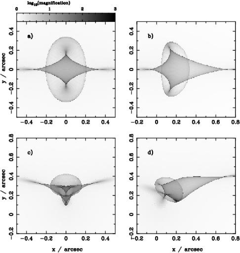
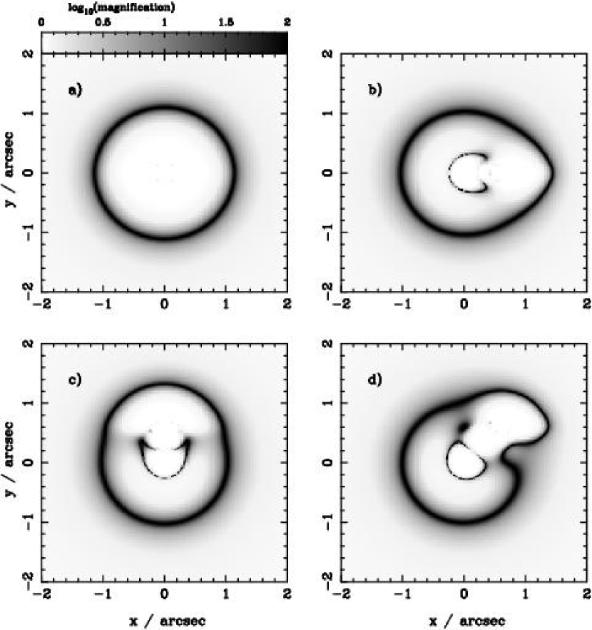
Fig. 1 shows the magnification maps in the source plane for various representative values of the disk offset. It is evident that a realistic shift in the disk position relative to the halo does indeed distort the caustic shapes severely. A shift in the x-direction, or in the plane of the disk, yields a shift of the diamond-shaped curves that form the tangential caustic, which is caused by the presence of the disk. The elliptical (radial) caustic, which is due to the peak in the central mass concentration of the combined halo and disk, reduces in size and is distorted in the direction of the offset. Offsets outside the plane of the disk lead to more complicated caustic geometries. The tangential caustic shifts and the upper cusp of the caustic appears to fold over into the diamond itself. The radial caustic changes its shape drastically, and is pinched inward near the lower cusp. But a comparison of Panel (c) and Panel (d) of Fig. 1 shows that an offset in the x-direction can partially reduce the effect of a shift in the y-direction.
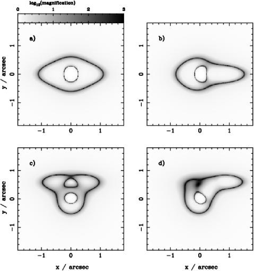
Fig. 2 shows the magnification maps in the image plane. The small inner critical curve corresponds to the radial caustic and the outer one corresponds to the tangential, diamond-shaped caustic. It is clear from these images that the locations of highly magnified images can be substantially affected by misalignments. As with the magnification maps in the source plane, offsets out of the plane of the disk also create complicated geometries. In Panel (c), Fig. 2, the upper, roughly triangular shaped critical curve has split from the inner critical curve. In Panel (d), Fig. 2, the region within this new critical curve has nearly collapsed. If the disk were shifted further in the x-direction then this new critical curve would be absorbed into the outer critical curve. The evolution of caustics and critical curves is continuous, i.e. the curves gradually distort, pinch off and absorb each other.
To investigate the effects of misalignment on total magnification, we calculate the magnification cross section ratio of the misaligned cases to the aligned case. The magnification cross section for a lens is derived by adding up the total number of pixels with a value greater than some threshold value in a magnification map. The results are shown in Fig. 3. An offset in the plane of the disk is seen to have little effect. But the cross section for high magnification events is significantly increased for offsets outside the plane of the disk. This is a manifestation of the large surface area very near the caustic curves in Panel (c) of Fig. 2. The offset in the y-direction of 0.6” corresponds approximately to the maximum possible enhancement in high magnification cross section for our lens model. The observed trend that offsets in the x-direction tend to compensate for the more dramatic effects of shifts in the y-direction is apparent here also.
This effect on the cross section for high magnifications is likely to have a measurable effect on the statistics of multiple image systems. Due to the preferential selection of high luminosity images in a survey, any flux limited sample of lens systems is biased towards systems with a large cross section for high magnifications (magnification bias, e.g. Borgeest, 1991). Therefore the fraction of lens systems with misaligned disks as estimated in § 2.1 is conservative, and the actual number of systems in which a misaligned disk is important might be larger.
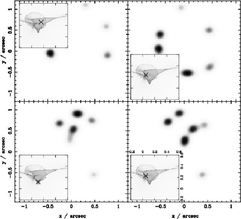
The number of images of a source will increase or decrease by two if the source crosses a caustic (see Schneider, Ehlers & Falco 1992 for a mathematical illustration of the same). An aligned halo and disk are capable of producing at most five separate images, in the configuration of a four-image, possibly asymmetric, Einstein cross with a demagnified central image. However, our distorted caustic geometries for the misaligned cases have regions where even higher image numbers are possible. For instance, the lens configuration of Panel (c), Fig. 1 has a region where seven images are formed and other lens configurations can produce even more images. Such a configuration with a large multiplicity of images has been observed; B1359+154 is a 6-image system (Rusin et al. 2001) where the lens is a compact group of galaxies at . These asymmetries in caustic geometries are expected to yield complicated, asymmetric image geometries. Fig. 4 illustrates examples of the kind of image geometries that can be produced with the increased parameter space provided by disk offsets. The inset within each panel shows the magnification maps in the source plane and location of the point source. A representative range of image geometries with a wide range of magnification ratios is shown. Current observations of such systems might not reveal their complexity entirely; for example the configuration shown in Fig. 4, Panel (c) might be easily confused for an Einstein cross because the separate demagnified image is likely to go undetected.
5 Lens properties of early-type systems
In the previous section we have concentrated on misalignment between the disk and halo component in late-type lensing galaxies with Milky Way-type spiral disks. The majority of lens systems known are, in fact, early type galaxies, as these tend to be more massive and hence have a larger cross section for lensing. Recent observations show that disks or disk-like structures might well be present in early-type lenses (Kelson et al. 2000). This suggests that early-type galaxies may contain disks that may also be misaligned with respect to the bulge/halo. Whether there is a possible misalignment between a disk and the (baryonic) bulge depends on the exact cause of the misalignment, but a scenario as described in § 2 may cause a misalignment between disk and the bulge as well as with the dark matter halo.
5.1 Magnification maps, cross-sections and image geometries
We investigate here the lensing properties of a misaligned disk component that is similar to that observed in ellipticals. In particular, we choose disk parameters that are comparable to those found by fitting the light profile of ellipticals in CL 1358+62 with a bulge+disk model as in Kelson et al. (2000). For our early-type lens model, we choose a disk scale length of which corresponds to the average disk scale length of the ellipitcals in CL 1358+62 at the cluster redshift of . The disk mass is taken to be . We model the bulge/halo as a CIS with and increase the total mass within to , to reflect the fact that early-type lens galaxies are usually more massive. This choice of parameters gives a velocity dispersion of 220 km/s and yields an Einstein radius of 1” for the bulge/halo.
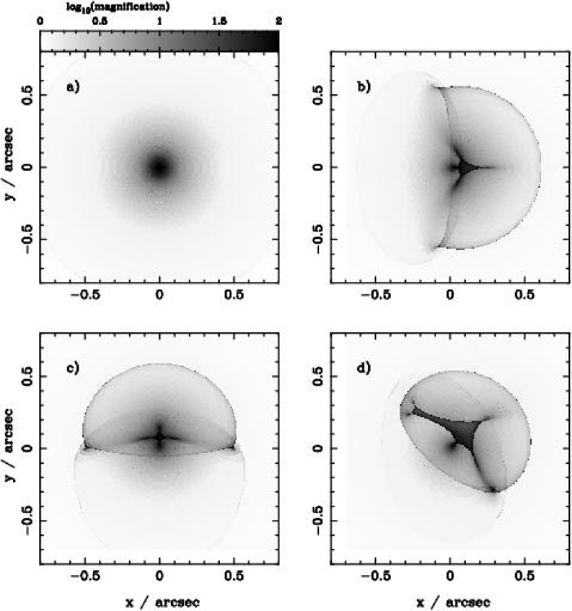
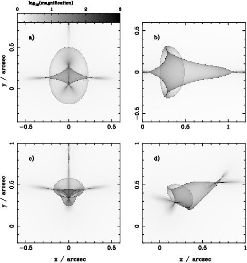
Fig. 5 shows the magnification maps in the source plane for the elliptical lens. The values for disk offsets are the same as in the previous section. Although this disk is less massive than the disk in our late-type lens, it is also significantly more compact, meaning that the central value is in fact high enough for the disk to produce an additional elliptical component to the overall caustic structure. So the magnification maps in Fig. 5 represent a superposition of two elliptical components due to the disk and the halo, as well as the tangential caustic due to the disk. Fig. 6 shows the corresponding magnification map in the image plane. As seen in Panel (a) of Figs. 5 and 6, our model of a compact disk has virtually no effect on the structure of the caustics or critical curves when the disk and halo are aligned. The circular critical curve in Fig. 6 is nearly a circular Einstein ring. The other panels of Fig. 6 show critical curves that are introduced by a misalignment of the compact disk.
Even though the disk components in the elliptical lens galaxy model contain a smaller fraction of the total mass than the disks in the late-type lens models discussed in previous sections, the effect of the misalignment between disk and halo is still very pronounced. In particular for misalignments in both the x and y direction, the effect on the structure of the caustics and critical curves is drastic. Since the majority of observed 4-image lens systems are expected to be produced by lensing of a point source that lies close to the high-magnification caustic lines, this indicates that the image properties of these systems are affected strongly by the presence of a misaligned disk, even if it is contributes only a small fratction of the total mass and has a scale length of less than a few hundred parsecs.
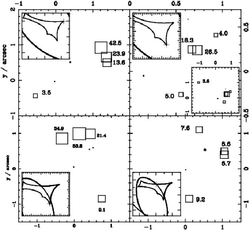
It is therefore likely that the image geometries will also change significantly. In Fig. 7 we show some typical image geometries of early-type lens systems with a misaligned disk for two different lens models. The boxes are centered on the image positions and have sizes that are proportional to the logarithm of the magnification. The numbers near the images give the magnifications of the image. Depending on the source position, both common and unusual image geometries may be produced. The bottom-left panel shows a fairly typical 3-1 geometry produced by a source near a cusp. In contrast, the top-left panel shows a case with non-standard magnification ratios; the central image is not the brightest image. These ‘inverted’ magnification ratios are a unique feature of complex multi-component lens models; as discussed below, single component mass models predict that the central image of the group of three images in 3-1 lens geometries is always the brightest. The top-right panel of Fig. 7 shows a lensed source near a cusp, but the 3-1 image geometry is not present. Instead there are four clustered images, with the two brightest ones nearly overlapping, and a fifth image lying at a distance of a few arcseconds. Finally, the source in the bottom-right panel does not lie on a cusp and the 3-1 image geometry is broken. All images have roughly similar magnification and there is no clear group of three closely grouped images.
6 Interacting halos
We point out in this section that even grazing interactions between neighboring halos are likely to produce transient misalignments due to tidal torquing. While these offsets might not persist for significant periods of time, they are worth exploring as a special case of the generic misaligned case. We use the diskhalo model described in § 4 but add a secondary halo with about 30% of the mass of the primary at a distance of one to several arc-seconds away from the primary lens. Simulations of such interacting halos suggest that the disk misalignment will tend to be along the direction of the secondary. We have explored a variety of halo separations and choose a distance of 1.7 arc-seconds to illustrate the effect. This separation in fact corresponds to a spatial distance of 2, where kpc is the disk scale length for the proto-type Milky Way type spiral. The magnification maps in the source plane are shown in Fig. 8. The main effects are an increase in the area enclosed by the caustics, an overall shift of the caustic structure, and induced distortions in the direction of the secondary halo. Comparing Panel (c) of Fig. 1 to Panel (c) of Fig. 8 also shows that the radial caustic is less pinched at the lower edge. Close pairs of galaxies are in fact observed as lenses; B1608+656 (Koopmans & Fassnacht 1999) is a clear example of this. If one or both of the lens galaxies in this system contain discs, a scenario as discussed above is likely to arise.
7 Magnification ratios
There has been much interest recently in explaining some of the observed magnification ratios with lens models that include compact substructure with masses that are approximately . Such substructure is ubiquitous in numerical simulations of structure formation in standard cold dark matter cosmologies, but has not yet been observed. An argument in favor for the possible ubiquity of dark clumps is that there are many viable mechanisms that could prevent star formation in such compact sub-halos (Somerville 2002) so that they could indeed exist but be unobservable directly.
Gravitational lensing does in principle provide a method to detect dark matter substructure on these small scales, and the recent arguments presented by Metcalf & Madau (2001), Metcalf & Zhao (2002), Dalal & Kochanek (2002) and Bradać et al. (2002) are compelling. The current claim is that in systems like B1422+231, the observed image magnification ratios cannot be obtained without substructure. The most general and convincing case was originally presented by Schneider & Mao (1998) for B1422+231 where there are 3 highly magnified images on one side of the lens centre (images A,B and C), forming a line. On the other side of the lens lies a single, fourth image D, that has a radio flux that is a factor of 50 lower than that of the other three images. This means that either image D is demagnified or the other 3 images are magnified very strongly. This, however would imply that the source has to lie close to a cusp. There exists a theorem that holds strictly only for sources on a cusp: the sum of the flux of the outer two images ought to be equal to the flux of the innermost image, or, written in terms of the magnifications:
| (2) |
where B is the central, brightest, image. However, the images in B1422+231 do not obey this relation. Moving the source away from the cusp would mean the theorem need not hold but implies that the total magnification is small and hence that image D needs to be strongly demagnified. Mao & Schneider (1998) argue that this is unlikely as the image is far from the lens center and hence in a low region, leaving only the possibility that the source does lie close to a cusp but that the magnification of one or more of the images is effected by substructure in the vicinity.
Recently, Keeton et al. (2002) investigated the lensing properties of sources lying in cusps in more detail. His analysis is based on a generic one-component elliptical power law lens model, including external shear. He finds that the image magnification ratios of a number of observed lens systems, B2045+265, RX J0911+0551 and B0712+472 can not be fit by such ”cusp lenses”. No detailed modeling is done in that paper and the argument is based on the deviant magnification ratios alone. The magnification ratio of observed systems lies typically between 1.5 and 2 for total magnifications of . One-component lens models of these systems predict a magnification ratio that is within a few per-cent of unity. The question arises whether the mismatch between observed and simulated image magnification ratios is not due to the specific one-component lens model used; a more complicated lens mass profile may explain the observed magnification ratios.
As seen from the maps in Figs. 1-8 mergers and misalignments between a halo and disk can cause a strong change in the magnification pattern on the image plane. It is thus not unreasonable to propose that the magnification ratios might be explained by a more complex structure in the primary lens – for example the presence of a misaligned disk, as discussed in this paper.
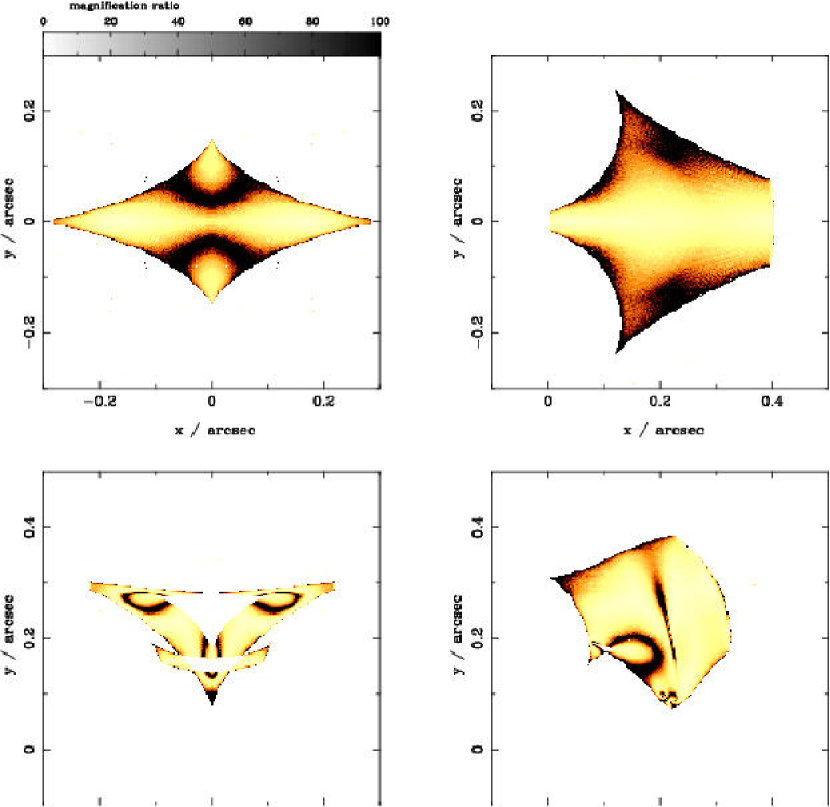
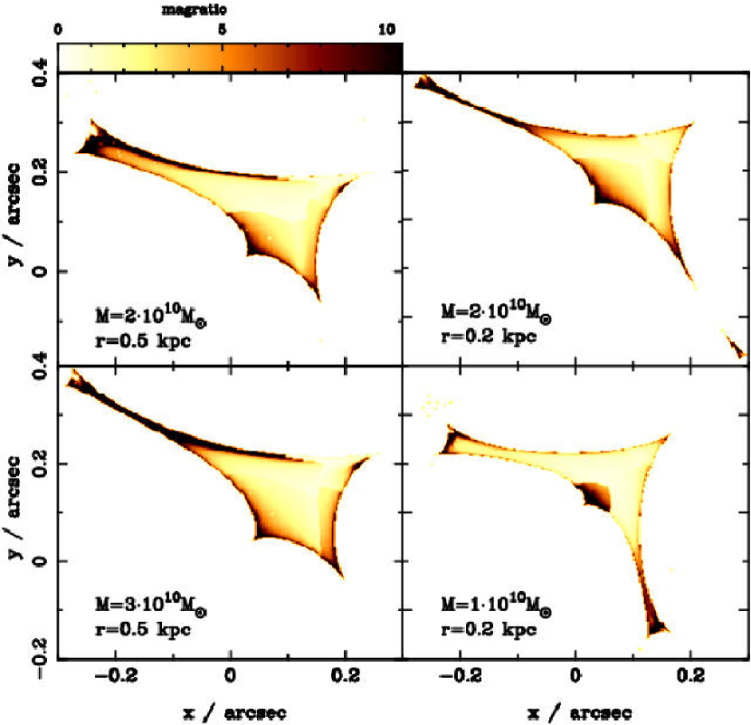
In Figs. 9 and 10 we show the magnification ratio for our Milky Way-type model and for the early-type lens respectively for different offsets and disk parameters. In all cases, only regions in the source plane that would produce 4 detectable images are shown. In the case of the Fig. 9 this is only true for regions in the source plane that form a total of 5 images. For the early-type lens model, regions that produce a total of 7 images in general also produce 4 bright images, the remaining three images being strongly demagnified (cf. Fig 7, top-left and bottom-left panels). To determine the magnification ratios for these systems we proceed as follows: for each source position as defined by a grid on the source plane consisting of pixels of size arcsec, we identify the 4 most strongly magnified images. Within this group, the image with the smallest magnification, image D, is identified. Within the remaining group of three magnified images we identify the central image as image B. The remaining two images are assigned labels A and C randomly. Having thus identified the images A,B,C and D for each source position, we determine the magnification ratios from the individual magnifications as described in § 3.
The gray-scale in Figs. 9 and 10 is such that lightly-shaded regions indicate source positions for which the magnification ratios do not obey the cusp relation. The top left panel in Fig. 8 shows the case for no halo-disk misalignment for our Milky Way-type lens model; the disk in the remaining three panels has a moderate misalignment in the x, the y and the x-y direction. The caustic shape changes significantly once the disk is misaligned, leading to strong changes in the function of magnification ratio vs. source position. Especially for a misalignment in the y directory (top-left panel) and for misalignments of , the caustic shape becomes very complicated and in several cusp regions the expected magnification differs drastically from that expected in ”normal” cusps. For the early-type lens, we show the magnifcation ratio only for offsets of , but for different disk parameters. The top left panel is for the standard early-type lens model described in the previous section. The three other panels are for three different sets of disk masses and sizes. The bottom-right panel shows the results for a small, light disk. In all cases sources lying in the upper-right cusp would produce 3-1 image geometries with magnification ratios that differ significantly from the expected ratio of 1.
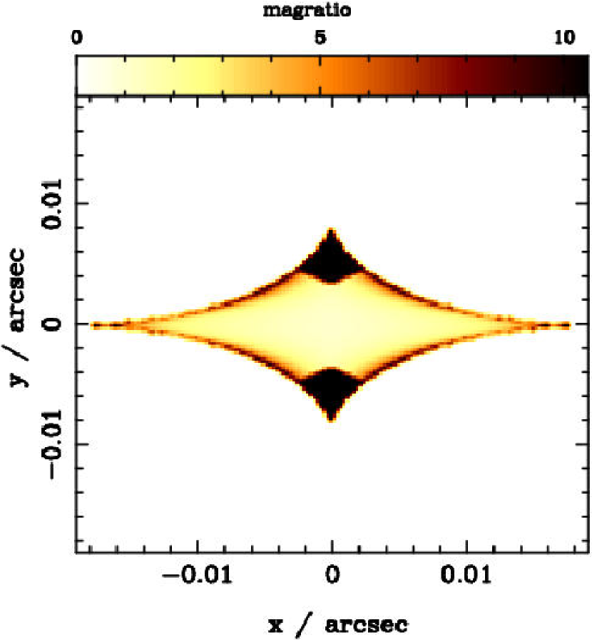
Note that for the Milky Way-type lens there is a strong effect due the presence of the disk even when it is not misaligned. We show the corresponding result for our standard early-type lens model in Fig. 11. The scale is drastically different than that of Figs. 9 and 10; the caustic structure is very small. Since we assume a spherical halo, the asymmetry in the potential that causes the inner caustic is solely due to the small disk embedded in the halo. However, there is not much qualitative change compared to the MW-type lens: a disk affects the magnification ratios of 4-image lens systems strongly also in E-type lens galaxies. This is in concordance with the findings of Möller, Hewett & Blain who studied the effects of such aligned disks in early-type lensing galaxies (MNRAS, submitted).
8 Conclusions
As has been illustrated in the plots in this paper, the presence of a misaligned disky component embedded in a dark matter halo produces a complex range of strong lensing effects - in the shapes and areas of the caustics, magnification ratios, and image geometries.
Most importantly, we show that for models of high-magnification () systems the presence of a disky component can substantially alter the expected magnification ratios and image geometries. This is true for both Milky Way-type disks and small disks as may be found in early-type galaxies. But misalignments of the disk relative to the halo, such as might be caused by mergers or strong interactions, can compound this effect. The shape of the caustic structure changes dramatically, and depending on the ellipticity of the dark matter halo the enclosed area is enhanced by up to a factor of 10. Thus, misaligned disks increase the overall cross-section for the formation of four magnified images, while at the same time causing strong deviation from the magnification ratios expected from simple one-component lens models. Single component, elliptical mass models are unable to reproduce such features, which may be the reason why models based on simple elliptical mass models fail to reproduce the observed image magnification ratios as for B1422+231.
Due to the complexity of the lens model investigated here we have been concerned mainly with investigating the qualitative effect of misaligned disks. Even though detailed modeling of existing systems using a halo in combination with a misaligned disk lens is in principle possible, this will be a complicated and time-consuming task. Due to the large number of parameters and the relatively few observational lensing constraints, it is very unlikely that a definite model can be found; instead, it is to be expected that there will be a considerable degree of degeneracy. However, our results do show clearly that the simple one-component lens models currently used are likely to be too simplistic and that more complicated models including a possibly misaligned disk component can reproduce the observed properties of many lens systems without introducing the need for halo sub-clumps.
References
- (1) Barnes, J., & Hernquist, L., 1998, ApJ, 495, 187
- (2) Blandford, R., & Narayan, R., 1992, ARA&A, 30, 311
- (3) Brown, I, et al., 2001, Proc. of Gravitational Lensing: Recent Progress and Future Goals, ASP Proc. Vol. 237, p.15.
- (4) Cole, S., & Lacey, C., 1996, MNRAS, 281, 716
- (5) Dubinski, J., & Kuijken, K., 1995, ApJ, 442, 492
- (6) Fassnacht, C., Xanthopoulos, E., Koopmans, L.V.E., & Rusin, D., preprint, astro-ph/0208420
- (7) Kassiola, A., & Kovner, I., 1993, ApJ, 417, 450
- (8) Keeton, C., Kochanek, C., & Seljak, U., 1997, ApJ, 482, 604
- (9) Keeton, C., Gaudi, B.S., & Petters, A.O., 2002 , preprint, astro-ph/020
- (10) Kelson, D. D., Illingworth, G. D., van Dokkum, P. G., & Franx, M., 2000, ApJ, 531, 137
- (11) Kochanek, C., & Dalal, N., 2002, ApJ, 572, 25
- (12) Koopmans, L.V.E., & Fassnacht, C.D, 1999, ApJ, 527, 513
- (13) Mao, S., Witt, H., & Koopmans, L.V.E., 2001, MNRAS, 323, 301
- (14) Mao, S., & Schneider, P., 1998, MNRAS, 285, 587
- (15) Metcalf, B., & Madau, P., 2001, ApJ, 563, 9
- (16) Möller, O., & Blain, A., 1998, MNRAS, 299, 845
- (17) Möller, O., & Blain, A., 2001, MNRAS, 327, 339
- (18) Möller, O., Natarajan, P., Kneib, J.-P., & Blain, A., 2002, ApJ, 573, 562
- (19) Mihos, C., & Hernquist, L., 1994, ApJ, 425, L13
- (20) Nelson, R.m & Tremaine, S., 1995, MNRAS, 275, 897
- (21) Patton, D. R., et al., 2002, ApJ, 565, 208
- (22) Rest, A., et al., 2001, AJ, 121, 2431
- (23) Rusin, D., et al., 2001, ApJ, 557, 594
- (24) Schneider, P., Ehlers, R., & Falco, E., 1992, Gravitational Lensing, Published by Springer-Verlag.
- (25) Sheth, R., Mo, H. J., & Tormen, G., 2001, MNRAS, 323, 1
- (26) Somerville, R., & Kollatt, T., 2000, MNRAS, 316, 479
- (27) Somerville, R., 2002, ApJ, 572, L23
- (28) White, S. D. M., & Frenk, C. S., 1991, ApJ, 379, 52
- (29)