Further author information: (Send correspondence to J.A.J.)
J.A.J.: E-mail: jjenkins@cfa.harvard.edu
Background Measurements from Balloon-Borne CZT Detectors
Abstract
We report detector characteristics and background measurements from two prototype imaging CdZnTe (CZT) detectors flown on a scientific balloon payload in May 2001. The detectors are both platinum-contact 10 mm 10 mm 5 mm CZT crystals, each with a 4 4 array of pixels tiling the anode. One is made from IMARAD horizontal Bridgman CZT, the other from eV Products high-pressure Bridgman CZT. Both detectors were mounted side-by-side in a flip-chip configuration and read out by a 32-channel IDE VA/TA ASIC preamp/shaper. We enclosed the detectors in the same 40∘ field-of-view collimator (comprising a graded passive shield and plastic scintillator) used in our previously-reported September 2000 flight. I-V curves for the detectors are diode-like, and we find that the platinum contacts adhere significantly better to the CZT surfaces than gold to previous detectors. The detectors and instrumentation performed well in a 20-hour balloon flight on 23/24 May 2001. Although we discovered a significant instrumental background component in flight, it was possible to measure and subtract this component from the spectra. The resulting IMARAD detector background spectrum (from 30 keV to 450 keV) reaches counts cm-2s-1keV-1 at 100 keV and has a power-law index of 2 at high energies. The eV Products detector has a similar spectrum, although there is more uncertainty in the energy scale because of calibration complications.
keywords:
CZT, background, balloon flights, hard x-ray astronomy1 INTRODUCTION
A sensitive survey of the sky in hard X-rays ( 10 - 600 keV) will require a coded-aperture design for imaging over a wide field of view, and this in turn requires a very large-area detector which is reasonably efficient even at the upper end of the energy band and has high resolution in position, energy, and time (see Grindlay et al, these Proceedings and astro-ph/0211415, for a description of the proposed EXIST mission). The most promising strategy for achieving these goals involves a high-Z, room-temperature semiconductor detector (CdZnTe, hereafter CZT) read out through an array of anode electrode pixels by multi-channel ASIC electronics.
In section 2 we will briefly describe the CZT2 experiment, emphasizing differences from the previous flight [1]. We used entirely new detectors for this flight, and the preparation and characterization of these detectors (one made from an eV Products crystal and the other from an IMARAD crystal) is described in section 3.
We had a successful, 20-hour balloon flight with CZT2 (section 4), which flew alongside several other instruments. In the course of data analysis (section 5), we discovered a significant instrumental background component of the spectrum using the multi-channel readout capability of our VA-TA ASIC, and we show two compatible methods for subtracting this (cosmic-ray related) instrument background to obtain photon background spectra which are relevant to future wide field-of-view coded-aperture telescopes. We conclude by explaining how our laboratory and balloon program will progress toward the goal of large-area survey telescopes by incorporating cathode readouts for depth-sensing and large-area modular detectors with integrated electronics.
2 THE CZT2 EXPERIMENT
CZT2 consists of two 10 mm 10 mm 5 mm CZT detectors flip-chip mounted to a carrier board, a 32-channel VA-TA ASIC readout from IDE AS, an ASIC controller board and PC-104 computer, shield assembly and readout, and power supplies and filters for the electronics. All of the equipment is enclosed in a cylindrical pressure vessel so the experiment can be flown with one atmosphere of nitrogen to resist high-voltage breakdown and to facilitate cooling of warm components at balloon altitude.
CZT2 was designed to measure the background of a wide field-of-view pixel-array CZT detector under high-altitude, near-space conditions. A previous planar-detector CZT experiment (CZT1, see Bloser et al. 1998[2], Bloser et al. 2002[1]) explored the effectiveness of an active rear BGO shield on a wide-FOV detector; CZT2 relies on a graded Pb-Sn-Cu shield and an active plastic scintillator shield for charged particle rejection. Both of these approaches (BGO and plastic active shielding) remain in consideration for a survey mission.
2.1 Instrumental configuration
We have described CZT2 in its original form previously [1], so here we emphasize the modifications used for the current flight; aside from the new platinum-contact detector (section 3), there are three main improvements to the set-up: (1) better grounding between components of the system and several new cables and power supplies optimized for lower noise; we were able to operate CZT2 with a lower discriminator setting throughout the flight, yielding better low-energy response. (2) Removal of an 241Am calibration source in the FOV; the calibration source dominated the sky background in the previous flight, and nearly eliminated sensitivity below 70 keV. Without the calibration source, we were able to measure the background down to 30 keV. Furthermore, since we re-used the ASIC from the previous flight, we re-used the temperature-gain relation measured by centroiding the 241Am photopeak to sharpen the spectra obtained in the absence of an in-flight calibration. (3) Switch from custom serial-port to ethernet link between the CZT computer and out central EXITE computer. Ethernet provides a faster a more reliable connection between pressure vessels, which increases the maximum data rate the system can process, reduces dead time accrued when the CZT computer is sending data rather than acquiring it, and simplifies the custom software by making greater use of off-the-shelf libraries capable of reliably transmitting data structures with simple procedure calls. Other current and planned instruments in our group (CZT3, EXITE 3/4) will also use commercial high-speed serial technologies such as ethernet and USB wherever possible to shift computing power away from the detectors toward centrally-located flight computers which process data for many detector modules. Figure 1 shows a schematic diagram of the CZT2 detector assembly and support electronics.
 |
 |
2.2 Previous flight
On September 19, 2000, CZT2 flew for the first time [1] with two gold-contact CZT detectors (one eV material, the other IMARAD) and measured a background of counts cm-2 s-1 keV-1 at 100keV. The background spectrum was roughly flat below 100 keV (although the in-flight calibration source limited sensitivity below 70 keV), and rolled over into a power-law with photon index above 100 keV.
3 DETECTOR FABRICATION AND CHARACTERISTICS
3.1 Detector Material and Contacts
For the May, 2001 flight we replaced the detectors in CZT2, again using one high-pressure Bridgeman eV crystal and one horizontal Bridgeman IMARAD crystal, but this time applying platinum contacts. In our previous work with gold-contact IMARAD CZT detectors [3] we have found that despite forming a Schottky barrier with p-type IMARAD material and thus reducing dark current through the detector, the gold has variable adhesion properties such that a relatively low yield of operable detectors was obtained with IMARAD CZT using Au contacts. We substituted platinum contacts for gold in this flight in the hope that Pt would preserve the electrical properties of Au against CZT but adhere more reliably.
The detectors were prepared at Goddard using the same contact application procedure for both crystals. Each bare crystal (eV and IMARAD) was first etched with dilute bromine methanol solution to remove surface damage. Then of platinum was evaporated onto the crystal using a shadow mask. The anode electrode pattern, a array of pixels surrounded by a thin guard ring, is identical to the pattern we used in the September 2000 flight. After passivation, the surface resistivity is between the cathode and a single anode pixel.
3.2 Dark Current Measurements
After the flight, we measured the dark current in each pixel as a function of bias voltage in order to evaluate the resistance properties of the detectors in detail.
CZT2 is not optimized for low-noise readout in a number of ways; e.g., the circuit board connecting the ASIC to the detector socket has leads which are both long and of variable length, and the computer controlling the experiment is located in the same pressure vessel as the detector and ASIC. This means that CZT2 is not capable of pushing energy resolution down to the limits of the detector/ASIC combination (a few keV) where dark current contributions to system noise would reveal themselves directly in the FWHM. The following dark current measurements thus represent a short cut; a way of evaluating the ultimate noise contribution to the system due to dark current, even when that noise is too small to appear in spectra.
Figure 2 shows I-V curves for the eV-material detector. Each plot in the grid corresponds to the physical position of a pixel on the detector anode. The curious result here is the variation in the curves from pixel to pixel: some pixels have curves which suggest Schottky barriers for negative bias (e.g. second row pixels), others seem ohmic (e.g. bottom row, left two pixels). The ohmic pixel behaviour seen with Au-contacts on eV Products CZT[3] was with significantly lower leakage current than found here. We speculate that the eV Products CZT in the present detectors may contain inclusions or be non-uniform in some other way, perhaps with respect to zinc fraction, so that parts of the surface are slightly n-type while others are slightly p-type or intrinsic. When platinum (slightly p-type) contacts are applied, I-V curves and the presence of diode-like behavior could then depend on the precise composition of the crystal under a particular anode pixel.
Figure 3 shows the corresponding plot for IMARAD material, which is slightly n-type. In this case, we see much more consistent Schottky barrier behavior, with the exception of the upper-left pixel. Because this is only a single pixel in the corner of the detector, it may be due to surface leakage cased by imperfect passivation. Both the IMARAD and eV Products detectors have nA dark current at -500 V bias in the best pixels, with all but one of the IMARAD detector pixels at 2 nA vs. only 4 of the eV detector pixels.
 |
 |
4 BALLOON FLIGHT RESULTS
We had a successful 20-hour balloon flight from Fort Sumner, NM beginning with launch at 16:24 UTC, 15 May 2001. The flight was a collaboration with the HERO hard x-ray focusing optics group at MSFC, and was also the final flight of Harvard’s EXITE2 phoswitch/coded-aperture telescope [4]. CZT2 acquired data at float altitudes of 119,000 ft to 126,000 ft for hours.
4.1 Energy Calibration and Temperature correction
We calibrated the ASIC pulse height/energy relation using six spectral lines from three different radioactive sources (241Am, 57Co, and 133Ba) placed successively in the field of view while CZT2 was being tested on the ground. The six lines (or rather, five lines plus the 241Am escape peak) range in energy from 30 keV to 356 keV, and show that the ASIC is nearly linear in that range, although saturates slightly above 500 keV (with the exact value depending on the channel) with our gain settings.
The ASIC channels connected to the eV detector are significantly noisier, on average, than those connected to the IMARAD detector because of longer circuit board traces between the ASIC and detector. Because of this, the calibration data for the eV detector is incomplete (many eV channels had to be masked out during the calibration runs). The IMARAD detector spectra are calibrated, and we concentrate on spectral results from that detector.
Because the ASIC and its support electronics were unchanged from the September 2000 flight, we assume that the effect of temperature on the system gain and pedestal offset is similar to that observed in the earlier flight, with a calibration source, even though we did not fly a source during the May 2001 flight. We correct for temperature using a simple model derived from Bloser et al. 2002, figure 4, in which the gain does not change over the relevant temperature range for the 2001 flight ( C), and the pedestal offset (as measured by the location of the in-flight 241Am cal source 60 keV peak and the ASIC low-energy noise peak) increases linearly with temperature.
4.2 Subtraction of the Instrumental Background
During test runs on the ground before flight, the system showed very low background in the absence of test sources. In flight, however, we measured a background component even in ASIC channels which were electronically disabled. The VA-TA ASIC has a feature which allows us to disable channels so they will not trigger a readout (viz., photons interacting in the corresponding anode pixels will be ignored). Nevertheless, disabled channels are still read out when an event in some other (active) pixel triggers a readout. The spectrum obtained from a disabled channel represents either a measure of ambient noise in the system, or some kind of residual glow caused by photons or cosmic rays triggering active channels but also depositing charge in the disabled channels.
We have found that high-energy events in the disabled channels tend not to be correlated with high-energy events in the active channels; this suggests that the background in the disabled channels is, in fact, an instrumental background. Because it appears only at high-altitude, it must be cosmic-ray related, perhaps the result of noise induced by the elevated shield rates or charged particles interacting with some stage of the readout electronics. Under the assumption that we are seeing an instrumental background component, it follows that a similar component should be present in the spectra obtained from the active channels. The photon background spectrum for a wide FOV detector, dominated by aperture flux but also containing locally-produced photons, should be obtained by subtracting a disabled-channel spectrum from an active-channel spectrum to remove the instrumental noise events. We approach this in two ways, described below.
4.2.1 Instrumental Background Subtractions in Individual Pixels
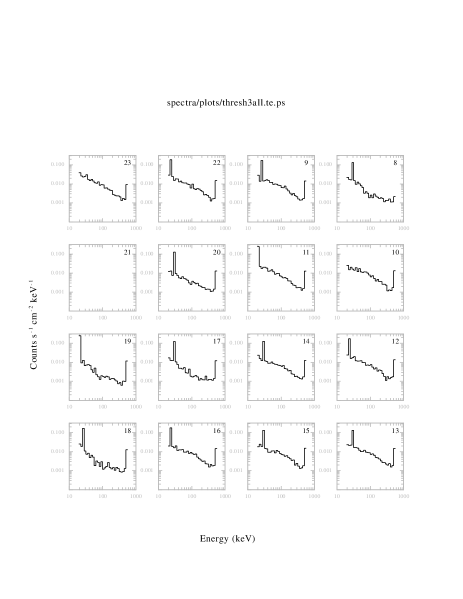
We limited our telemetry rate for the CZT2 experiment to 50 events per second to reduce dead time caused by computer processing. Given this constraint, there is a trade-off: we could choose a low lower-level discriminator (LLD) setting and push the low-energy response down at the expense of having to disable many of the noisier channels, or we could raise the LLD and activate more channels. During the flight, we used two configurations most of the time. In the first configuration (cf. spectra in figure 4), five channels are disabled (those marked 8 and 17 - 20) and the LLD is set to an energy corresponding to roughly 30 keV. In the second configuration, four of these channels (8, 17, 18, and 20) are re-activated as the LLD is re-set to correspond to keV.
 |
As long as we restrict attention to energies above 45 keV, we can subtract the instrumental background on a channel-by-channel basis in a straightforward way, but only for the four channels which switched from being disabled to active as the LLD was raised: we divide each block of data by the appropriate integration time, and subtract a channel’s extracted spectrum in the “disabled” data set from that in the “active” data set. We show the results of this procedure in figure 5.
 |
4.2.2 Instrumental Background Subtraction Averaging Many Pixels
The method described above suffers from two disadvantages. First, the data come from only 4 of the 15 working IMARAD channels, so relatively few photons go into each spectrum and statistical uncertainties are high. Second, the data is limited to energies higher than 45 keV, the higher of the two LLD settings.
An alternative approach is to assume that the gains, efficiencies, and pedestal offsets of all pixels are similar, and in a single data set (namely, the 30 keV threshold data) average together the 10 active channel spectra and the 5 disabled-channel spectra, and subtract the latter average from the former. We show the results of this method, which is clearly vulnerable to systematic uncertainties resulting from variations among the channels, in figures 6 (average spectra before subtraction) and 7 (subtracted spectum).
 |
4.3 Comparison with Predicted Background and Previous Flight
Our background measurements are consistent with the measurements made during the 2000 flight, although they extend the low-energy response from 70 down to keV. Bloser et al. (2002) describe an MGEANT simulation of the CZT2 background spectrum which includes contributions from aperture flux (which is dominant), shield leakage, and local production due to cosmic ray interactions with the apparatus[1]. Figure 7 shows spectra from the 2001 flight along with the simulation results.
 |
5 CONCLUSIONS AND FUTURE WORK
We have found that platinum contacts adhere well to CZT crystal, and provide reliable current-limiting Schottky barriers with IMARAD material in the same way gold does. Performance is variable, even over a single detector, for our detector made from eV Products CZT. Using two new detectors and other improvements to the system, we had a successful balloon flight with the CZT2 instrument during which we obtained a measurement of the background at high altitude for a wide-FOV CZT detector with active plastic and passive lead-tin-copper graded shields. There was a significant instrumental background, probably related to cosmic rays interacting with the electronics, at high altitude; we characterized and subtracted this component of the background by taking advantage of the multi-pixel readout capability of the VA-TA ASIC. The resulting subtracted, detector-only background, dominated by aperture gamma-ray flux but also containing a component caused by local production of photons, is similar to what we have measured before: a flat spectrum at counts s-1 cm-2 kev-1 from 30-100 keV, turning over into a photon-index 2 power-law at higher energies. This spectrum is in rough agreement with our MGEANT simulations, although the normalization, turnover point, and high-energy slope do not line up precisely with what we measured.
We have constructed a larger-area (8 cm 8 cm) CZT detector, CZT3, which incorporates the IDE XA ASIC in an integrated module with the detector carrying board[5], and we have begun to incorporate a cathode readout into that system (also using IDE ASICs) to provide depth-sensing capability. Future balloon instruments (EXITE3 and EXITE4) will be large-area scientific detectors (up to 0.5 m2) composed of tiled CZT/ASIC modules similar to those in CZT3. These instruments will incorporate cathode readouts and will also test thicker CZT detectors, detectors with smaller pixel pitch, and different ASIC technologies over the next several years.
6 ACKNOWLEDGEMENTS
We thank B. Ramsey, J. Apple, K. Dietz, and the rest of the MSFC HERO team for technical support on our shared balloon gondola, and NSBF for a successful flight. B. Sundal at IDE AS and U. El-Hanany at IMARAD provided help with the VA-TA ASIC readout and CZT crystals respectively. Francis C. Niestemski at the College of the Holy Cross made many of the detector I-V measurements. This work was supported in part by NASA grants NAG5-5103 and NAG5-5209, and J. A. J. acknowledges support from an NSF Graduate Student Research Fellowship.
References
- [1] P. F. Bloser, T. Narita, J. A. Jenkins, M. Perrin, R. Murray, and J. E. Grindlay, “Balloon flight background measurement with actively-shielded planar and imaging CZT detectors,” in Proc. SPIE Vol. 4497, p. 88-99, X-Ray and Gamma-Ray Instrumentation for Astronomy XII, Kathryn A. Flanagan; Oswald H. Siegmund; Eds., 4497, pp. 88–99, Jan. 2002.
- [2] P. F. Bloser, J. E. Grindlay, T. Narita, and F. A. Harrison, “CdZnTe background measurement at balloon altitudes with an active BGO shield,” in Proc. SPIE Vol. 3445, p. 186-196, EUV, X-Ray, and Gamma-Ray Instrumentation for Astronomy IX, Oswald H. Siegmund; Mark A. Gummin; Eds., 3445, pp. 186–196, Nov. 1998.
- [3] T. Narita, B. F. Bloser, J. E. Grindlay, and J. A. Jenkins, “Development of gold contacted flip-chip detectors with IMARAD CZT,” in Proc. SPIE Vol. 4497, p. 86-96, Hard X-Ray, Gamma-ray, and neitron detector physics II, R. B. James; R. C. Schirato; Eds., 4141, pp. 86–96, 2000.
- [4] P. F. Bloser, Y. Chou, J. E. Grindlay, T. Narita, and G. Monnelly, “Development of an xspec-based spectral analysis system for the coded-aperture hard X-ray balloon payload EXITE2,” Astroparticle Physics 17, pp. 393–400, July 2002.
- [5] T. Narita, J. E. Grindlay, J. A. Jenkins, M. Perrin, D. Marrone, R. Murray, and B. Connell, “Design and preliminary tests of a prototype CZT imaging array,” in Proc. SPIE Vol. 4497, p. 79-87, X-Ray and Gamma-Ray Instrumentation for Astronomy XII, Kathryn A. Flanagan; Oswald H. Siegmund; Eds., 4497, pp. 79–87, Jan. 2002.