Line Profiles from Different Accretion Engine Geometries
Dept. of Physics and Astron., Univ. of Rochester, Rochester NY 14627
DAMTP, Cambridge Univ., Wilberforce Rd., Cambridge CB3 OWA, UK
1. Motivation and Example Profiles for Four Classes of Geometries
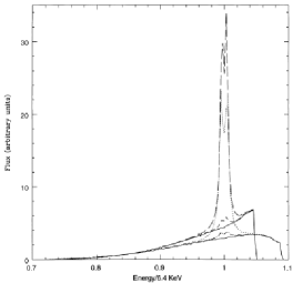
Cold matter in AGN and some X-ray binary engines can reprocess the primary X-ray continuum (e.g. George & Fabian 1991) and produce a fluorescent iron K emission line near 6.4keV whose profile contains information about the geometry/dynamics of the accretion engine (Fabian et al. 2000). Thin discs illuminated from above by an X-ray point souce reproduce many data features (e.g. Tanaka et al. 1995; Nandra et al. 1997) but variety in the data still motivates calculation of line profiles from other plauible disc geometries. (all profiles shown below are computed for Schwarzchild holes):
Concavity (Fig. 1, left): Sufficiently concave discs enhance the peak near the rest frequency (Blackman 1999), an effect which may also be transient.
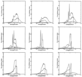
Warps (Fig. 1, right): Here nonaxisymmetry is important (Hartnoll & Blackman 2000): the inclination angle and the azimuthal viewing angle both determine the profile, unlike a flat disc for which all azimuthal viewing angles are equivalent. Time variability of the line profile is expected on the time-scale of any warp precession around the disc. Shadowing also changes the equivalent width of the line as a function of azimuthal viewing angle. Other possible features: (1) sharper peaks near the rest frequency compared to flat disc. (2) sharp red peaks or steep red fall-offs, and/or soft blue fall-offs from shadowing and nonaxisymmetry. (3) deep minima states from shadowing.
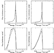
Clumps (Fig. 2, left): This alternative, including outflows, (Hartnoll & Blackman 2001) is motivated by studies of the survival of cold dense clouds in AGN engines (Kuncic et al. 1997). When embedded in advection dominated accretion flows (ADAFs, e.g. Narayan & Yi 1995), iron lines can be produced. These profiles have less sensitivity to inclination angle than flat discs.
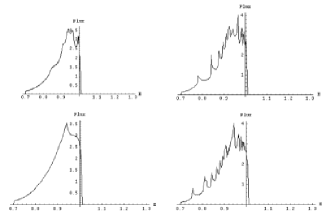
Spirals (Fig. 2, right): Line profiles for discs which have spiral velocity structure (Hartnoll & Blackman 2002) show multiple, quasi-periodic sub-peaks and/or step-like structures in the blue wing of the line profile for high inclination discs, and a dependence on azimuthal viewing angle from nonaxisymmetry. Time variability is expected on time scales of the sprial wave propagation.
References
Blackman, E. G. 1999, MNRAS, 306, L25
George, I. M. & Fabian, A. C. 2002, MNRAS, 249, 352
Hartnoll, S. A. & Blackman, E. G. 2000, MNRAS, 317, 880
Hartnoll, S. A. & Blackman, E. G. 2001, MNRAS, 324, 257
Hartnoll, S. A. & Blackman, E. G. 2002, MNRAS, 332, L1
Kuncic Z. et al., 1996, MNRAS, 283, 1322
Nandra K. et al. 1997, ApJ, 477, 602
Narayan, R. & Yi, I., 1995, ApJ 444, 231
Tanaka Y. et al., 1995, Nature, 375, 659