The Effect of External Winds on Relativistic Jets
Abstract
Relativistic jets in Galactic superluminals and extragalactic AGN may be surrounded by a wind near to the central engine. Theoretical analysis and numerical simulation reveal considerable stabilization of relativistic jet flow by a wind to helical and higher order asymmetric modes of jet distortion. When velocities are measured in the source (inlet) frame, reduction in the absolute velocity difference between jet and wind, , provides stabilization in addition to stabilization provided by a high jet Lorentz factor, but a high Lorentz factor wind is not needed to stabilize a high Lorentz factor jet. However, the fundamental pinch mode is not similarly affected and knots with spacing a few times the jet radius are anticipated to develop in such flows. Thus, we identify a mechanism that can suppress large scale asymmetric structures while allowing axisymmetric structures to develop. Relativistic jets surrounded by outflowing winds will be more stable than if surrounded by a stationary or backflowing external medium. Knotty structures along a straight jet like that in 3C 175 could be triggered by pinching of an initially low Mach number jet surrounded by a suitable wind. As the jet enters the radio lobe, suppression of any surrounding outflow or backflow associated with the high pressure lobe triggers exponential growth of helical twisting.
1 Introduction
Numerical studies (see Meier, Koide & Uchida (2001) and references therein) and theoretical work (Begelman & Blandford, 1999) indicate that relativistic jets may be surrounded by a more slowly moving wind. Flow in the environment outside the jet can have important consequences for its stability, and the twisted normal mode structures that appear on resolved jets. In this paper we present results from a numerical simulation of a precessed elliptically distorted relativistic jet. The simulation was designed to explore the interaction between helical twisting arising from precession and the twin helically twisted filaments predicted to accompany elliptical distortion. In the simulation the jet develops a velocity shear (wind) layer which has significant consequences for the evolution of the initial perturbation. The results are relevant to the development of structures in relativistic Galactic and extragalactic jets.
2 Simulation Setup
The simulation used a new numerical 3D relativistic hydrodynamical code. A description of the code along with validation tests and comparison to previous 2D simulation results to establish the reliability of the techniques can be found in Hughes et al. (2002). The present simulation employed a uniform 3D Cartesian grid resolved into 108 108 549 zones. The 108 zones along the transverse Cartesian axes span a distance of 8R, the 549 zones span a distance of 41R along the jet () axis, and 27 zones span a jet diameter, 2R. In the simulation the jet is initialized across the entire grid, jet and ambient proper densities are equal, the jet is in pressure balance with the ambient medium, the Lorentz factor = 7.47 (vj = 0.991 c), the adiabatic index = 13/9 and the sound speed a = 0.62 c. A precessional perturbation of angular frequency R/ = 0.5 is applied at the inlet by imposing a transverse component of velocity = 0.0025 c. An elliptical perturbation is also applied at the inlet by imposing an elliptical cross section of eccentricity 0.51 on the jet at the inlet with rotation of the major axis at the same angular frequency as the precessional perturbation.
In the simulation outflow boundary conditions are used except on the plane where the jet enters the computational grid. Inflow is imposed on the plane , and involves cells cut by the jet boundary for which state variables must be established through a volume-weighted average of the internal and external values. To avoid a ‘leakage’ of jet momentum into the ambient material, fixed, initial values are used across the entire boundary plane at every time step. However, the high momentum density of the jet (approximately an order of magnitude higher than that of the flows discussed by Hardee et al. (2001)) means that even modest numerical viscosity is capable of transferring a significant momentum to the ambient material beyond the inflow plane, leading to a sheath of marginally relativistic flow. We note that we are using a second order scheme for a nearly laminar flow containing weak structures, and that many studies, starting with that of (Porter & Woodward, 1994), have shown that in such cases the numerical viscosity acts in a way very similar to true viscosity. Although the magnitude of the numerical viscosity might not agree with that of the true viscosity we believe that our current prescription does not build anomalous behavior into our numerical solution.The simulation was terminated at dynamical time ta/R = 45.2 when a quasi-steady state developed on the computational grid.
3 Simulation Results
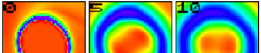
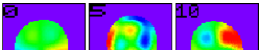
Figure 1 contains panels showing proper density slice planes transverse to the jet () axis. The panels show that the jet is surrounded by a low density (dark blue) region that grows in transverse extent as distance from the inlet increases. Flow is into the page and in these panels precession and elliptical rotation are counterclockwise and spiral density (pressure) waves in the external medium can be seen in the panel at the inlet (top left). Twin higher density filaments are evident in the panels at z/R = 5 & 10 as red regions within a yellow (lower density) envelope. The filaments rotate by about 225 degrees between these two panels in the clockwise direction. At larger distance the twin filaments disappear and only a general elliptical distortion of the jet along with some displacement of the jet from the -axis due to helical twisting can be seen in the panels.
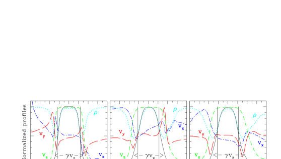
The transverse velocity and density structure of the jet is indicated more quantitatively by the profiles at 5, 20 & 35 shown in Figure 2. The approximate edge of the jet (jet spine) is indicated by the vertical lines in the panels and coincides with rapid change in the azimuthal velocity component, vy. In general, the azimuthal velocity changes direction outside the jet spine. As can be seen from these transverse profiles, the low density medium outside the jet spine develops significant outflow that grows in transverse extent and speed as distance from the inlet increases, i.e., the axial velocity profile becomes broader relative to the edge of the jet as distance from the inlet increases.
.
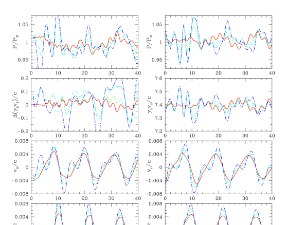
Plots of the pressure, proper density and velocities along 1-D cuts parallel to the jet axis are shown in Figure 3.
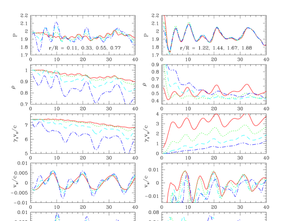
Inside the jet pressure and density cuts show 1.5R, 3R, 4R, & 12R fluctuations. Transverse velocity component cuts reveal 6R & 12R fluctuations. The 4R, 6R & 12R fluctuations are identifiable with twin density filaments inside the jet at z/R 10, elliptical distortion of the jet cross section, and with helical twisting of the jet, respectively. The 1.5R at z/R 11 and 3R fluctuations seen here in the pressure, density and axial velocity are identifiable with pinching. There is no significant growth of the initial perturbation on the computational grid. Outside the jet the cuts show that pressure fluctuations are communicated without loss to at least a jet radius outside the jet spine. Density cuts show the greatly reduced density around the jet spine and axial velocity cuts show the growth in wind speed in the medium outside the jet spine as distance from the inlet increases. Radial motions outside the jet spine increase out to and then decline, and azimuthal motions increase out to and then decline.
In the next section we will show that the presence of velocity shear outside the jet spine, treated as a simple uniform external wind, can explain much of the behavior seen in the simulation. If we assume that the jet spine interacts with the external medium within a layer of thickness 2R (suggested by a transition to undisturbed ambient at x/R 3 in the profiles shown in Figure 2 and a theoretically predicted exponential decline in perturbation amplitude outside the jet surface), then we may regard the external medium as having a “wind” speed for .
4 Theoretical Interpretation
We can analyze flow driven structures, e.g., Hardee (2000), Hardee et al. (2001), by modeling the jet as a cylinder of radius , having a uniform density, , and a uniform velocity, , along the -axis. The external medium is assumed to have a uniform density, , and to have a uniform velocity, , along the -axis. The jet is assumed to be in static pressure balance with the external medium . A general approach to analyzing the time-dependent structures is to linearize the fluid equations along with an equation of state where the density, velocity, and pressure are written as , and , and subscript 1 refers to a perturbation to the equilibrium quantity. In cylindrical geometry a random perturbation of , and can be considered to consist of Fourier components in the source (inlet) frame of the form
| (1) |
where the flow is along the z-axis, and is in the radial direction with the flow bounded by . In cylindrical geometry is the longitudinal wavenumber, is an integer azimuthal wavenumber, for the wavefronts propagate at an angle to the flow direction, the angle of the wavevector relative to the flow direction is , and and refer to wave propagation in the clockwise and counterclockwise sense, respectively, when viewed outwards along the flow direction. In equation (1) 0, 1, 2, 3, etc. correspond to pinching, helical, elliptical, triangular, etc. normal mode distortions of the jet, respectively. For normal mode the axial wavelength associated with a helical twist of a wavefront around the jet beam is given by where . Propagation and growth or damping of the Fourier components is described by the dispersion relation
| (2) |
In the dispersion relation the primes denote derivatives of the Bessel () and Hankel () functions with respect to their arguments, subscripts and refer to the jet and external medium, respectively,
and
In the expressions above is the unperturbed Lorentz factor, and is the sound speed given by
| (3) |
where is the adiabatic index, the flow velocities are measured in the source frame and the densities are measured in the proper fluid frames. With these definitions the dispersion relation allows , sound speeds a large fraction of lightspeed, and is a simple generalization of previous work (e.g., Ferrari et al. 1978; Birkinshaw 1991; Hardee et al. 1998).
In previous work it has been assumed that the external medium is stationary relative to the source with and and typical behavior of solutions to the dispersion relation for relativistic supersonic flow in a stationary external medium is well documented in the literature (e.g., Birkinshaw 1991: Hardee et al. 1998; Hardee 2000). Here in Figure 4 we show solutions to the dispersion relation for the pinch fundamental (pf), helical (hs) and elliptical (es) surface, and accompanying first body (b1) mode distortions to a cylindrical jet with Lorentz factor = 7.47 (vj = 0.991 c), adiabatic index = 13/9 and sound speed a = 0.62 c for cases when there is no flow of the external medium, ve = 0 and , and when there is a wind flow ve = 0.5 c and , of the external medium relative to the source. In both calculations the sound speed and adiabatic index in the external medium are a = 0.62 c and = 13/9.
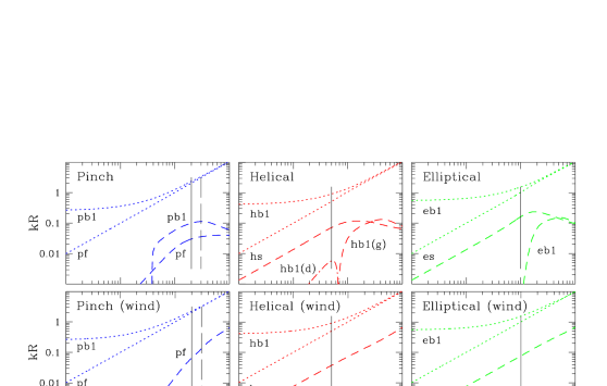
When there is no wind the helical body (hb1) solution is damped (dot-dash line) at the precession frequency and growing at higher frequencies. With the exception of the pinch fundamental (pf) mode all solutions have a maximum growth rate at some supersonic “resonant” frequency. With no wind we would expect to see growth of the initial precessionally driven helical surface (hs) and elliptical surface (es) perturbations along with body modes (pb1 & eb1) across the computation grid. In the presence of a wind the solutions show that the growth rates of the surface modes at the precession frequency are suppressed by about a factor of 2, the body solutions are either purely real or weakly damped (weak damping of hb1 is shown), the supersonic resonance has disappeared, and growth of the fundamental pinch mode (pf) has increased to greater than the growth rate of the surface modes at the frequencies of interest.
The pinch mode fundamental wave solution can be found from the dispersion relation in the low frequency limit and . In this limit , and the dispersion relation becomes
where we have used and . As faster than , the real part of the solution to the dispersion relation remains nearly unmodified by the presence of a wind around the jet and
| (4) |
The imaginary part of the solution is vanishingly small in the low frequency limit.
The body wave solutions are somewhat modified by the presence of a wind surrounding a jet and in the limit and the dispersion relation becomes
where we have used , , and is a correction term given by
The solutions are given by
| (5) |
where is an integer. When there is no wind and . Previously we found that unstable body wave solutions exist only when the denominator in equation (5) is real and that body mode growth rates, with the exception of the first pinch body mode, are small unless the jet is sufficiently supersonic in both jet and external medium.
In the low frequency limit and where , , the dispersion relation for the surface modes, , becomes
where we have used . Thus, the low frequency analytical approximation for helical (hs), elliptical (es) and higher order surface modes is
| () |
| () |
where
and growth corresponds to the plus sign in equation (6a) and minus sign in equation (6b). The normal mode propagation speed (real part of eq.[6a]) increases as wind speed increases but the growth rate (imaginary part of eqs.[6a,b]) decreases as wind speed increases. The growth length becomes
| () |
It is not surprising that the presence of a wind speeds up wave motion in the source frame, and reduces the temporal and spatial growth rate in the source frame through reduction in the velocity shear. Thus, longer growth lengths in the source frame, equation (7), are not unexpected. It is suprising to find that the growth rates and the growth length can be shown to depend directly on the velocity shear, , independent of the Lorentz factor.
This analytically predicted effect applies at the precession frequency in the simulation and explains the reduction in the growth rate of the surface modes shown in Figure 4. Note that a high Lorentz factor wind is not necessary for significant stabilization and is in addition to stabilization provided by 1. If the external medium is inflowing then in equations (6a), (6b) and (7), the growth rate is increased and the growth length decreases in the source frame. Structure associated with normal modes can be modeled theoretically using expressions giving the pressure and velocity structure (Hardee et al. 1998; Hardee 2000; Hardee et al. 2001), and compared to structure seen in the simulation. In Figure 5 we show suitably normalized 1-D cuts from the simulation along with theoretical 1-D cuts generated using a combination of pinch fundamental (pf), helical surface (hs), and elliptical surface (es) and first body (eb1) modes. The damped helical body solution (hb1) is not included and we find no evidence for its presence in the simulation. We have chosen solutions at the frequencies indicated by the solid lines in Figure 4 and adjusted the amplitudes to correspond as nearly as possible to the fluctuations observed in the simulation. Note that the amplitudes of the theoretical and simulation pressure fluctuations are comparable. Slight differences in location of maxima and minima between theory and simulation are primarily the result of the use of a constant wavelength in the theoretical fits whereas the simulation wavelengths change slightly along the jet as the wind develops. The simulation cuts in vz are normalized to show fluctuations vz)/c. The fluctuations along the simulation 1-D cuts at r/R = 0.55 & 0.77 in Figure 5 must be multiplied by a factor of 2 & 3, respectively.
Short wavelength axial velocity and pressure fluctuations ( 3R) are fit by the pinch fundamental mode (pf). Even shorter wavelength fluctuations ( 1.5R) seen in the simulation at are consistent with the first pinch body (pb1) mode at the maximum growth rate. This solution has not been included in the theoretical fit. A long wavelength ( 14R) oscillation in the pressure corresponds to a standing conical pressure wave pattern at the relativistic Mach angle. The elliptical body mode (eb1) at , evident in the pressure and axial velocity fluctuations, appears rapidly and then disappears at .
Radial and azimuthal velocity fluctuations are almost entirely the result of helical (hs) and elliptical (es) surface modes and their amplitudes slowly decline across the computational grid. In general, we can match the position of simulation fluctuations to within about a jet radius in the axial direction. While there are detail differences between simulation and theoretical fit, these differences lie primarily in the axial velocity fluctuations in the outer half of the jet where the jet Lorentz factor has dropped significantly in the simulation, but the theory assumes uniform axial velocity and Lorentz factor.
The fits shown in Figure 5 identify the normal modes conclusively and also reveal (not shown here) that solutions without a wind fail because production of the velocity fluctuations observed in the simulation then requires theoretical pressure fluctuations much higher (factors of 2) than observed in the simulation. The disappearance of the elliptical body mode (eb1) and the pinch body mode (pb1) is a result of the development of the shear layer at . The growing shear layer, here modeled theoretically as a uniform external wind, has completely stabilized these body modes and at least partially stabilized the helical and elliptical surface modes.
Fitting the fluctuations seen in the numerical simulation involves computation of theoretical data cubes that can be compared to the simulation data cubes. Figure 6 shows pressure slice planes through the theoretical data cube that can be compared to the simulation proper density slice planes shown in Figure 1. In this rendering only the jet is shown.
Twin high pressure filaments are evident in the slice planes at . This is the expected structure for the elliptical body mode at the precession frequency. Elliptical distortion shows up best in the slice at with pressure minima at the ends of the major axis and pressure maxima at the ends of the minor axis. The lack of symmetry reflects interaction with the pressure maximum and minimum related to helical twisting. Clockwise rotation of the pressure maximum associated with helical twisting can be followed in the panels from .
5 Discussion
In the simulation small perturbations, jet precession and elliptical cross section distortion, were applied at the inlet to study the interaction between helical and elliptical jet distortion. Somewhat surprisingly, as the jet is predicted to be Kelvin-Helmholtz unstable, the numerical simulation showed a decline in the amplitude of the helical and elliptical surface mode perturbations across the computational grid. The simulation also revealed a relatively short wavelength fundamental pinch mode, moving at nearly the jet speed and with a constant amplitude across the computational grid. Although there was internal jet structure associated with pinch and elliptical body modes just outside the inlet, there was a lack of internal jet structure in the outer 3/4 of the computational grid. Previous simulations at lower Lorentz factor contained internal structure across the computational grid (Hardee et al., 2001).
Development of a shear layer of thickness 2R at outside the jet spine is responsible for the lack of growth of the asymmetric modes and for a larger growth rate for the fundamental pinch mode. Similar results have been found theoretically and confirmed by simulation for non-relativistic MHD jets (Hardee & Rosen, 2002). The effect of a shear layer, modeled as a simple wind, is shown to reduce the growth of perturbations significantly. Suppression of growth by a wind is related to reduction in the velocity shear and a high Lorentz factor wind is not needed to stabilize a high Lorentz factor flow. The theory indicates that growth of helical and elliptical surface mode distortions is reduced by a factor of 2 for a c/2 wind and would be reduced by a larger factor for the wind observed in the simulation at large distances from the inlet. Other change in the normal mode solutions within the computed frequency range, such as the disappearance of a maximum growth rate, greatly enhanced growth rate of the fundamental pinch mode, and suppression of the body mode growth rate occurs as the solutions are very sensitive to small changes in conditions when the velocity shear is weakly supersonic. Suppression of the body modes explains the lack of internal jet structure in the simulation.
Our present results suggest that a suitable shear layer or wind could partially stabilize a low Mach number relativistic astrophysical jet to helical and higher order modes of asymmetric jet distortion while leaving the fundamental pinch mode to grow. This provides a trigger for knots moving with the jet speed and with spacing a few times the jet radius near to the central engine. From this result we conclude that jets and, by implication, the accretion process onto the central black hole can be steadier than previously thought, while still producing rapidly moving knots with quasi-periodic spacing. We note that the mechanism found here is quite different from that investigated by Agudo et al. (2001), in which a shock moving with the jet fluid excited trailing components that could be identified with the first pinch body mode and were moving much slower than the jet fluid.
Spatial change in the wind speed such as a reduced wind speed at larger distance from the origin and/or decrease in sound speeds and increase in the jet Mach number would lead to a change in dynamical behavior. Rapidly moving knots near to the central engine might trigger and be replaced by more slowly moving knots associated with rapidly growing pinch body modes on the supersonic jet. More rapidly growing asymmetric structures might also be expected to accompany this change. Additional rapid growth of asymmetries would accompany jet propagation through backflow from a high pressure radio lobe as a result of increase in the velocity shear, , and significant increase in the growth rate (see eqs.[6a,b]) and decrease in the growth length (eq.[7]).
Knotty jet structure is observed in over half of the extended 3CR quasars observed by Bridle et al. (1994). The jets may be relatively straight over much of their length, e.g., 3C 175, or exhibit significant curvature on the parsec and larger scales, e.g., 3C 204 [see Bridle et al. (1994); Hough et al. (1999)]. The jet in 3C1̇75 (Figure 7) provides a possible illustration of the effects of external flow on jet dynamics.
A string of knots is observed along a straight jet that relatively abruptly bends and terminates in a hot spot and “U” shaped region at the outer edge of the radio lobe. VLBI observations suggest at least one knot like component beyond the core aligned with the large scale jet that could be moving superluminally (Hough et al., 2002), as would be expected if knots were associated with triggering of the fundamental pinch mode in a wind outflow near to the central engine. At larger distance the jet is not likely embedded in a rapid outflow and knots could be slowly moving pinch body modes or simple line-of-sight crossing effects associated with twisted filaments related to the elliptical surface and/or elliptical body mode. There is little appearance of asymmetric structure before the bend which is coincident with the trailing edge of the radio lobe in radio intensity images. The relative abruptness of the bend, although much less abrupt if deprojected, is suggestive of exponential growth of the helical mode, possibly triggered by backflow from the high pressure outer edge of the radio lobe.
References
- Agudo et al. (2001) Agudo, I., Gómez, J.L., Martí, J.M., Ibáñez, J.M., Marscher, A.P., Alberdi, A., Aloy, M.A., & Hardee, P.E. 2001, ApJ, 549, L183
- Begelman & Blandford (1999) Begelman, M.C., & Blandford, R.D. 1999, MNRAS, 303, L1
- Birkinshaw (1991) Birkinshaw, M. 1991, in Beams and Jets in Astrophysics, ed. P.A. Hughes (Cambridge: CUP), 278
- Bridle et al. (1994) Bridle, A.H., Hough, D.H., Lonsdale, C.J., Burns, J.O., & Laing, R.A. 1994, AJ, 108, 766
- Ferrari, Trussoni, & Zaninetti (1978) Ferrari, A., Trussoni, E., & Zaninetti, L. 1978, A&A, 64, 43
- Hardee (2000) Hardee, P.E. 2000, ApJ, 533, 176
- Hardee et al. (2001) Hardee, P.E., Hughes, P.A., Rosen, A., & Gomez, E. 2001, ApJ, 555, 744
- Hardee et al. (1998) Hardee, P.E., Rosen, A., Hughes, P.A., & Duncan, G.C. 1998, ApJ, 500, 599
- Hardee & Rosen (2002) Hardee, P.E., & Rosen, A. 2002, ApJ, 576, 204 (astro-ph/0205377)
- Hough et al. (1999) Hough, D.H. et al. 1999, ApJ, 511, 84
- Hough et al. (2002) Hough, D.H. et al. 2002, AJ, 123, 1258
- Hughes et al. (2002) Hughes, P.A., Miller, M.A., & Duncan, G.C. 2002, ApJ, 572, 713
- Meier, Koide & Uchida (2001) Meier, D.L., Koide, S., & Uchida, Y. 2001, Science, 291, 84
- Porter & Woodward (1994) Porter, D.H. & Woodward, P.R. 1994, ApJS, 93, 309