The Molecular Condensations Ahead of Herbig-Haro Objects. I Multi-transition Observations of HH 2
Abstract
We present a CSO and BIMA molecular line survey of the dense, quiescent molecular environment ahead of HH 2. The molecular gas is cold, 13 K, and moderately dense, 3 cm-3. A total of 14 species has been detected (including different isotopes and deuterated species). The relative abundances of the clump are compared with other dense molecular environments, including quiescent dark clouds, and active low and high mass star forming regions. This comparison confirms the peculiar chemical composition of the quiescent gas irradiated by the HH objects. Thus, from this comparison, we found that the HCO+, CH3OH and H2CO are strongly enhanced. SO and SO2 are weakly enhanced, whereas HCN and CS are underabundant. The CN abundance is within the range of value found in starless dark clouds, but it is low with respect to high mass star forming regions. Finally, the chemical composition of HH 2 confirms the qualitative results of the Viti & Williams (1999) complex chemical model that follows the chemical behavior of a molecular clump irradiated by a HH object.
Key Words.:
ISM: individual: HH 2 — ISM: abundances — ISM: clouds — ISM: molecules — Radio lines: ISM — Stars: formation1 Introduction
Herbig-Haro (HH) objects, which trace shock-excited plasma, are signposts of the intense outflow phenomena associated with star formation (e. g., Reipurth & Bally Reipurth01 (2001)). Several HH objects are found to have associated quiescent dense clumps ahead of them: HH 1/2 (see references below), HH 7-11 (Rudolph & Welch Rudolph88 (1988); Dent et al. Dent93 (1993); Rudolph et al. Rudolph01 (2001)), HH 34 (Rudolph & Welch Rudolph92 (1992)), NGC 2264G (Girart et al. Girart00 (2000)), HH 80N (Girart et al. Girart94 (1994), Girart01 (2001); Girart, Estalella & Ho Girart98 (1998)). Most of them have high excitation knots, i. e., with strong high excitation lines, such as [OIII] and H, strong UV lines and significant UV continuum radiation (e. g., Reipurth & Bally Reipurth01 (2001)). The quiescent clumps are characterized by the low temperature and narrow line widths of the molecular emission, and by the emission enhancement of HCO+ and NH3. In spite of the presence of the HH objects, there is a lack of apparent dynamical perturbation in the clumps. However, recent observations show clear signposts of star formation within the HH 80N clumps (Girart et al. Girart01 (2001)).
Girart et al. (Girart94 (1994)) suggested that the regions of enhanced HCO+ and NH3 emission were a consequence of the irradiation from the HH shock affecting the chemistry within a small dense clump nearby in the molecular cloud. It was supposed that the UV radiation would evaporate icy mantles and promote photochemistry in the enriched gas. Taylor & Williams (Taylor96b (1996)) modeled this situation with a simple chemistry and showed that HCO+ would arise from the interaction of C+ (derived from CO) with H2O liberated from the ice. The chemical enhancements would be transient, but predicted column densities were significant. Viti & Williams (Viti99 (1999), hereafter VW99) noted that the impact of a high radiation field on a dense gas should lead to a rich chemistry, and they therefore extended the 1996 model. They predicted that, in addition to HCO+ and NH3, a wide variety of species should arise with enhanced abundances, including CH3OH, H2CO, SO, SO2, and CN and that the effects in a single clump should last for years. Raga & Williams (Raga00 (2000)) showed that the photochemical effects created by the HH object should respond to its movement through the molecular cloud, and predicted that the enhanced regions should have a characteristic morphology.
|
-
a is the FWHM line width
-
b Overlapped with the NS 11/2,11/2–9/2,9/2 transition
Implicit in the model is the idea that molecular clouds are clumpy on a small scale. This was suggested by Taylor, Morata & Williams (Taylor96a (1996)) as a necessary assumption to interpret the relative spatial distributions of CS and NH3 in molecular clouds in terms of time-dependent chemistry. The clumps were required to be transient on a timescale of about one million years. Subsequent interferometer observations (e.g. Peng et al. Peng98 (1998), for TMC-1 Core D; Morata, Girart & Estalella Morata02 (2002) for L673) have supported the Taylor et al. model. Therefore, the HH objects may be regarded as probes of the transient substructure of molecular clouds. Wherever the probe encounters a small clump, a characteristic chemistry arises. This paper reports a search for that characteristic chemistry in the clump associated with HH 2.
The prototypical HH 1 and HH 2 objects (Herbig Herbig51 (1951); Haro Haro52 (1952)), located in the L1641N molecular cloud in Orion, provided the earliest spectral evidence that the HH objects trace strong shocks due to the presence of stellar winds (Schwartz Schwartz78 (1978)). Both HH 1 and HH 2 belong to the class of high excitation HH objects, with strong UV (Böhm et al. Bohm87 (1987); Raymond, Hartmann & Hartigan Raymond88 (1988); Raymond, Blair & Long Raymond97 (1997)) and centimeter continuum emission (Rodríguez et al. Rodriguez90 (1990), Rodriguez00 (2000)). HH 2 shows a very complex and apparently chaotic morphological, kinematical and excitation structure (e. g., Schwartz et al. Schwartz93 (1993); Eislöffel et al. Eisloffel94 (1994)). Detailed HST observations reveal that this complex structure is the consequence of the interaction of the HH 2 jet with a dense ambient cloud, resulting in a very bright, high ionization and complex structure (Hester, Stapelfeldt, & Scowen Hester98 (1998)). Recent Chandra observations reveal that the strongest HH 2 knot, which is also the highest excitation knot, has associated X-ray emission (Pravdo et al. Pravdo01 (2001)).
The presence of quiescent dense ambient gas ahead of HH 2 has been well established from HCO+ and NH3 observations (Davis, Dent & Bell Burnell Davis90 (1990); Torrelles et al. Chema92 (1992), Chema94 (1994); Choi & Zhou Choi97 (1997)). The ammonia emission shows a clumpy medium, with clump sizes of only 20′′ (Torrelles et al. Chema92 (1992)) or AU (assuming a distance of 390 pc: Anthony-Twarog Anthony82 (1982)). JCMT observations by Dent (Dent97 (1997)) shows that the chemical composition of the dense ambient gas is strongly altered by the presence of the HH 2 radiation, with a strong emission enhancement of the HCO+. Wolfire & Königl (Wolfire93 (1993)) carried out a shock model where the X-ray, EUV and FUV radiation field from HH 2 penetrates the cloud, initiates an ion chemistry, enhancing the abundances of the HCO+ and the electrons, which produces an excitation enhancement of the HCO+. The combination of these two effects lead to a strong emission enhancement.
In this paper we present 0.8–1.4 mm CSO observations towards the quiescent clump ahead of HH 2. We also present 3 mm spectra obtained with the BIMA array. The goal of this paper is to study the chemical effect produced by the strong HH 2 radiation over the dense quiescent ambient gas around HH 2. A second paper will analyze and discuss the spatial distribution of the molecules observed with the BIMA array (Girart et al. GEHVW02 (2002), hereafter Paper II).
2 Observations and Results
|
||||||||||||||||||||||||||||||||||||||||||||||||||||||||||||||||||||||||||||||||||||||||||||||||||||||||||||||||||||||||||||||||||||||||||||||||||||||||||||||||||||||||||||||||||||||||||||||||||||||||||||||||||||||||||||||||||||||||||||||||||||||||||||||||||||
-
a is the FWHM line width

Observations were carried out in October 1999 with the 10.4 m telescope of the Caltech Submillimeter Observatory111The Caltech Submillimeter Observatory is funded by the National Science Foundation under contract AST-9615025 (CSO). The 200-300 GHz and 300-400 GHz receivers were used in conjunction with 50 MHz and 500 MHz acousto-optical spectrometers, which provided velocity coverage of 60 and 600 km s-1 at 250 GHz and of 40 and 400 km s-1 at 350 GHz. Pointing, focus and calibration were checked every few hours using Saturn. The main-beam efficiency, measured by observing Saturn, were 67% at 250 GHz and 60% at 350 GHz and system temperatures ranged 240–670 K. All the spectra were observed at the position: ; . This position is very close () to the HH 2 knot L (e. g., Hester et al. Hester98 (1998)) and to the peak emission of the HCO+ 4–3 integrated map from Dent (Dent97 (1997)). Table 1 lists all the molecular lines observed along with their rest frequency, the angular resolution at the observed frequency and the Gaussian fits to the line profiles. The upper limits show the 3- level within the 5.2-7.8 km s-1 range.
The 10–antenna BIMA array222 The BIMA array is operated by the Berkeley–Illinois–Maryland Association with support from the National Science Foundation. observations were carried out between 1999 October and 2001 May in the C configuration. A detailed description of the observations and reduction is given in Paper II. In order to compare with the CSO spectra, we smoothed the BIMA maps by convolving them with a Gaussian, with a resulting FWHM beam of , the angular resolution of the CSO observations at 230 GHz. A spectrum of each transition observed with BIMA was synthesized at the position observed with the CSO telescope (see paragraph above). Table 2 lists all the molecular lines observed, their rest frequency, and the Gaussian fits to the line profiles.
Figure 1 shows the spectra of the detected lines with the CSO and the BIMA observations smoothed to the angular resolution. A total of 33 transitions (including hyperfine transitions) were detected for 14 species: 13CO and C18O, HCO+, H13CO+, HC18O+, HCN, H2CO, CN, CH3OH, CS, SO, SO2 and the deuterated species DCO+ and DCN. The spectral lines peak at a within the range of km s-1 (CS and HCN) to km s-1 (HCO+). This range of values is in agreement with previous observations of the quiescent gas ahead of HH 2 (Torrelles et al. Chema92 (1992); Choi & Zhou Choi97 (1997)). The line widths range from km s-1 for the DCO+ to km s-1 for HCO+ and HCN. The 1 mm CS and HCN transitions have large line widths, 2.4 km s-1. However, this value is not significant due to the low SNR of these lines. The differences in line center velocity and line width are significant and are due to the combination of velocity gradients within the quiescent ambient gas and a spatial chemical differentiation, which will be discussed in Paper II. Yet, for the HCO+ the larger line width can also be due to a high optical depth and the presence of high velocity emission. The HCO+ 1–0 spectrum shows clearly redshifted and blueshifted wings, which implies the presence of high velocity molecular gas. This high velocity component is tracing the interaction between the HH object and the clump, which confirms the spatial association of the clump with HH 2 (Paper II).
2.1 HH2 and the clump
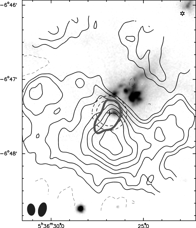
Figure 2 shows the distribution of the quiescent molecular gas, traced by the 13CO emission, ahead of the HH 2 region. There is clear column density enhancement, mainly downstream of HH2, whereas at the position of HH 2 or just behind it there is little ambient gas. The SO emission is also shown to better locate the chemically enhanced region just ahead of HH 2, almost coincident with HH 2 knot L (e. g., Hester et al. Hester98 (1998)). The high excitation HH 2 emission, as well as the X-ray and the radio continuum emission, arise from the brightest and largest knot in the [SII] image (see Fig 2).
3 Analysis
3.1 The Physical Conditions of the Quiescent Gas
HCO+, SO and CH3OH are the molecules with more than three transitions detected (including the rarer isotopes for the HCO+). Therefore, the observed emission from these molecules can be used to derive the physical condition of the quiescent gas. SO and CH3OH are molecules with moderate dipole moments, 1.55 and 0.90 Debyes, respectively, which implies that if the densities are not too low their emission will be close to thermalization. Thus, we carried out the population diagram analysis (e. g., Goldsmith & Langer Goldsmith99 (1999)) to derive the temperature of the gas and the column densities of SO and CH3OH. For the HCO+, since we have two rare isotopes observed, H13CO+ and HC18O+, we carried out the Monte Carlo radiative transfer model developed by Hogerheijde & van der Tak (Hogerheijde00 (2000)).
3.1.1 Population Diagram Analysis
The method used to carry out the population diagram analysis, which takes into account approximately the optical depth, is described in appendix § A. In order to obtain more accurate fits for the SO and CH3OH, which were observed with two different telescopes, a 20% calibration uncertainty was included in the estimated errors. Figure 3 shows the population diagram for the SO and CH3OH molecules.
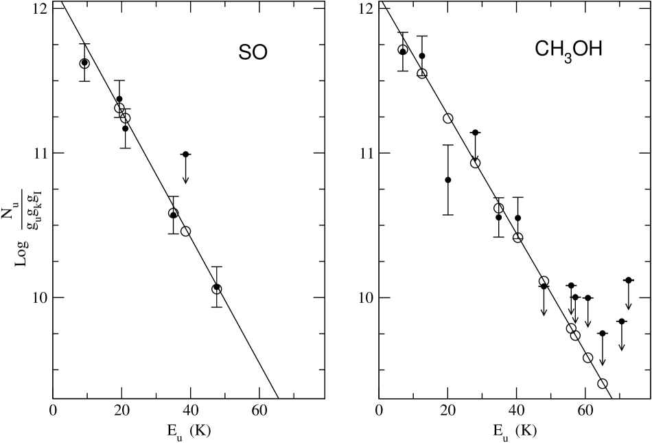
The SO emission is best fitted for K, (SO) cm-2 and a filling factor of . This solution gives moderate optical depths for the observed transitions, with a maximum value of 1.0 for the 32–21 transition. The high angular resolution () BIMA SO 32–21 maps show that the integrated emission arises from a region with a deconvolved size of (Paper II), which implies a filling factor of approximately . Therefore, the best solution for the SO obtained using the method described in appendix § A, gives a filling factor in agreement with the observed value from the BIMA maps.
The population diagram technique for the CH3OH emission gives the best fit for K, (CH3OH) cm-2, and . The optical depths of the observed transitions are small: the maximum value is 0.56, for the 20–10 A+ transition. The smaller filling factor of the CH3OH solution with respect to the SO is because of its slightly smaller emitting area: (Paper II). We note that although the optical depths of the SO and CH3OH are small () the population diagram technique used here and described in § A gives column densities of 20% (CH3OH) to 30% (SO) higher than the standard population diagram technique where optically thin emission is assumed.
3.1.2 Monte Carlo Radiative Transfer Code
We used the one dimensional version of the Monte Carlo code developed by Hogerheijde & van der Tak (Hogerheijde00 (2000)), which calculates the radiative transfer and excitation of molecular lines. The code is formulated from the viewpoint of cells rather than photons, which allows the separation of local and external contributions of the radiation field. This gives an accurate and fast performance even for high opacities (for more details see Hogerheijde & van der Tak Hogerheijde00 (2000)).
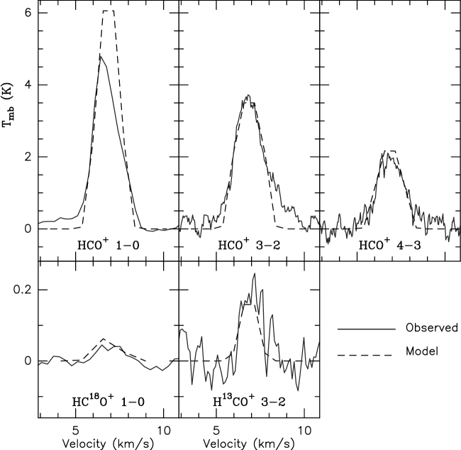
The HCO+ emission was assumed to arise from a sphere of radius cm or 6680 AU (17′′ at the distance of HH 2), which is approximately the radius of the BIMA HCO+ 1–0 emission for the peak intensity component (the HCO+ emission extends over a larger region to the NE of the peak intensity, but this extended component is not picked up by the CSO beam). The volume density and temperature were assumed constant and no velocity gradient was adopted (we note that the results are insensitive for radial velocity gradients of km s-1 within the adopted radius, i. e., 9 km s-1 pc-1). The 12C16O to 13C16O and 12C16O to 12C18O abundance ratios adopted were 63 and 560, derived for the Orion region by Langer & Penzias (Langer90 (1990), Langer93 (1993)). We explored a large range of values for the volume density, the temperature, the molecular fractional abundance and the intrinsic line width. The resulting synthetic maps of the different transitions were convolved with a Gaussian to match the angular resolution of the spectra ( for the 1–0 and 3–2 transitions and for the 4–3 transition). The best fit is obtained for a volume density of cm-3, a temperature of K, an intrinsic line width of km s-1, and a HCO+ fractional abundance of . Figure 4 shows the overlap of the observed and synthetic spectra for the HCO+, H13CO+ and HC18O+ transitions. The synthetic spectra fit well the observed spectra, except for the HCO+ 1–0. The lack of observed emission at the central and redshifted sections of the line, as compared with the predicted spectra, is possibly due to a combination of two effects. First, it could be due to the missing flux, a consequence of the lack of short spacing visibilities at the interferometer. Second, it is possible that the HCO+ 1–0 is affected by the absorption of a cold and low density component of the cloud, whose effects will only be observable in the lowest rotational transition of abundant species with high dipole moment (see Girart et al. Girart00 (2000)).
The assumed radius, derived from the HCO+ 1–0 maps, could be highly uncertain due to high optical depth, absorption by the foreground cold gas or resolving out the large-scale HCO+ emission. However, the models run with radii higher or lower than roughly a 30% of the value assumed do not fit the observed spectra. For small changes in the radii the best solutions are always in the 12-14K temperature range.
The temperature derived here is only slightly higher than the temperature derived from the SO and CH3OH population diagrams. This implies that the observed SO and CH3OH transitions are close to thermalization for the derived volume density, cm-3.
3.2 Excitation Temperature and Column Densities
From the previous analyses the derived temperature of the cloud is K. Yet, the rotational transitions of the observed molecules may have excitation temperatures significantly lower than this value because of subthermalization, i. e., the critical density of the transition is higher than the volume density of the cloud, cm-3. In particular this is the case for the high dipole moment molecules like HCO+ (3.90 Debyes), HCN (2.98 Debyes), H2CO (2.33 Debyes) or CS (1.98 Debyes). Thus, for example, the critical density of the H2CO 30,3–20,2 and CS 5–4 are 6 and 7 cm-3, respectively (Choi & Zhou Choi97 (1997)).
If at least two transitions are detected and the emission is optically thin, the excitation temperature can be obtained from the following two expressions:
| (1) |
and
| (2) |
where the subindices and refer to the rotational transitions, is the filling factor, is the Planck function in temperature units, and are the K-level and nuclear spin degeneracies, respectively, is the energy of the upper level of the transition, and the optical depth. In most of the cases here, the spectra of the transitions used to derive were obtained at the same angular resolution, so . HCO+, and CO are the only molecules with rarer isotopes observed. Therefore, for the other molecules, their emission is assumed to be optically thin.
The beam-averaged column densities of the observed species were derived assuming that the excitation temperature, , is the same for all the rotational transitions of the same species, with the exception of the SO and CH3OH, whose column densities were derived from the Population Diagram (§ 3.1.1).
3.2.1 HCO+
The HCO+ column density can be derived from the model carried out using the Monte Carlo radiative transfer code (§ 3.1.2) or directly from the line intensity ratios as described earlier (Eq. 2 and 1). From the model derived in § 3.1.2, the HCO+ beam-averaged column density for the best fitted model is 1.0 cm-2. On the other hand, for the intensity ratio method, the filling factor ratio of the 4–3 and 3–2 transitions, , should be derived in order to properly use Eq. 2 and 1. From the FWHM of the HCO+ 1–0 emission, 34′′ (see § 3.1.2) we can obtain a rough estimation of this ratio: . Thus from the line ratio analysis we estimate that the H13CO+ 3–2 transition is optically thin () and that the excitation temperature is within the 6.2-7.0 K range. Therefore, from the H13CO+ 3–2 integrated line intensity, the HCO+ beam-averaged column density is within the 3-5 cm-2 range. The line intensity ratio analysis derives an excitation temperature lower than the kinetic temperature obtained in § 3.1.2 and also a lower column density (by a factor 2-3). Uncertainties in the derived from the HCO+ 1–0 maps (see § 3.1.2) could account for this discrepancy. Alternatively, non-LTE effects, due to subthermalization, could also cause this discrepancy.
Since the DCO+ has a similar dipole moment as the HCO+, we adopted the same excitation temperature derived from the line ratios of the HCO+: within the 6-7 K range, the column density of the DCO+ column density is cm-2. This value is two orders of magnitude lower than that of the HCO+.
3.2.2 HCN
For the HCN we fitted the three hyperfine components of the 1–0 transitions using CLASS. The best solutions of the fit give moderate or low optical depths, , although the excitation temperature is not well constrained, K. However, the observed relative intensities of the F=1–1, 2–1 and 0–1 transitions, 1.70.2:3.90.4:1.0, do not agree with the 3:5:1 value expected under LTE conditions, but it is within the range of values measured in other molecular clouds (Guilloteau & Baudry Guilloteau81 (1981); Wannier et al. Wannier74 (1974); Walmsley et al. Walmsley82 (1982)). Velocity gradients and a non-uniform density could cause this “anomaly” (Guilloteau & Baudry Guilloteau81 (1981); Cao et al. Cao93 (1993); Gonzalez–Alfonso & Cernicharo Gonzalez93 (1993)). The 3–2 to 1–0 integrated intensity ratio yields an excitation temperature of K, significantly lower than that derived from the population diagram of the SO and CH3OH. This implies that the line emission is subthermalized, which could also cause the “anomaly” in the 1–0 hyperfine line ratios. The HCN beam-averaged column density was derived using K.
For the DCN, we adopted the same excitation temperature as the one for the HCN, 6 K.
3.2.3 H2CO
The two transitions detected yield an excitation temperature of K, implying that the emission is subthermalized (the upper limits of the undetected transitions are not tight enough to better constrain this value). As in the case of HCN and HCO+ this is due to its high dipole moment. In order to calculate the H2CO beam-averaged column density we used this excitation temperature and adopted an ortho to para ratio of 1.5, which should be reasonable for the H2CO formation and/or ortho-para conversion on grain surfaces (Dickens & Irvine Dickens99 (1999)).
|
-
a
Used a 12C16O/12C18O ratio of 560.
3.2.4 CS
The excitation temperature derived from the two transitions is K. This slightly higher excitation temperature than that derived from the other molecules is possibly due to its slightly lower dipole moment. As in the previous cases, this excitation temperature was used to derive the column density.
3.2.5 SO2
Of the five SO2 transitions observed, only two transitions were detected, 31,3–20,2 and 60,6–51,5. If their emission is optically thin, then their line ratio gives an unusually high excitation temperature, K, much higher than that derived from other molecules. At this temperature the 101,9–92,8 and 101,9–100,10 transitions should have been detected with BIMA. Therefore, this temperature seems unreliable. If an excitation temperature of about 10 K is assumed, then the line ratio gives an 31,3–20,2 optical depth of 10. From the radiative transfer equation for the optically thick case, , the filling factor can be derived and, therefore, a rough estimation of the source size, , (30′′ is the angular resolution of the spectra). The peak intensity of the 31,3–20,2 line, K, would imply a source size of only 5′′ if the line is optically thick. However, the BIMA maps of this transition show that the emission arises from a significantly larger area, (Paper II). Thus, we suggest that the 60,6–51,5 line emission is “anomalous”, although we cannot discern if this is an instrumental effect or if it is a real anomaly. In order to estimate the SO2 column density we used the 31,3–20,2 transition, assuming an excitation temperature of 10 K.
3.2.6 Other molecules
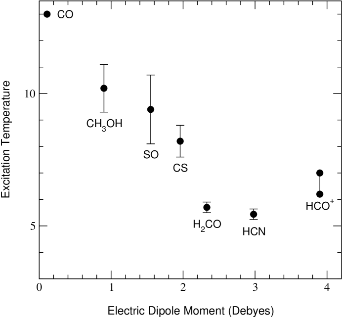
The CO and its isotopes have a low dipole moment, 0.11 Debyes, so their emission is likely thermalized. Therefore, the excitation temperature used to derived the CO column density is 13 K. Figure 5 shows the values of the excitation temperature versus the dipole moment of the analyzed aforementioned molecules. With the exception of the HCO+, there is a trend of decreasing with increasing dipole moment, , which is expected since higher implies more severe subthermalization. Fig. 5 can be used to roughly extrapolate the excitation temperature for the other observed molecules. Thus, we adopted a K for those molecules with Debyes (CN, OCS, H2S, HCS+, H2CS, HNCO, HCOOH and CH3SH) and K for the rest of the molecules (-C3H2, HC3N, CH3CN and NH2CN), which indeed have a dipole moment higher than 3 Debyes.
Table 3 shows the beam-averaged column densities derived from the observations. The fractional abundances of the observed molecules with respect to the CO molecule are also listed in this table (note that the estimated fractional abundance relative to the CO is a beam-averaged value).
4 Discussion
4.1 Chemical Comparison with other dense molecular regions
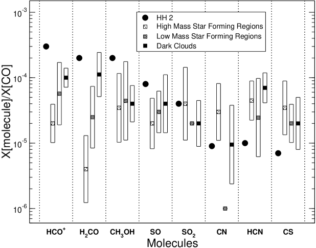
In order to be able to establish the effects of the shock-induced radiation from HH 2 on the chemical composition of the quiescent clump ahead of the HH object, it is necessary to compare the relative abundances of the molecules detected with respect to other environments associated with dense molecular material. Before the radiation reached the clump, this molecular cloud had likely the properties of the starless dark molecular cores. It is well known that there are important chemical differences between starless dark clouds and star forming regions, and that there are important gradients within the same molecular cloud, a consequence of the evolutionary effects or due to the presence of nearby star formation sites (e. g., van Dishoeck & Blake Dishoeck98 (1998)). Since we want to compare the general chemical properties of the molecular clouds with those from the molecular emission ahead of HH 2, we have estimated the logarithmic median and standard deviation of the relative abundance (with respect to CO) of the molecules detected in HH 2 and compare this with a sample of three different types of molecular environments: high mass and low mass star forming molecular clouds, and starless dark molecular clouds. Figure 6 shows shows this comparison.
Interestingly, from Figure 6, the observed molecules ahead of HH 2 can be classified into four groups, depending on their abundance with respect to other molecular clouds. (1) Strongly enhanced molecules: HCO+, CH3OH and H2CO. Their relative abundances are enhanced mostly within a factor of 5 to 10 with respect to the typical values found in the molecular clouds. In particular, the enhancement of HCO+ and H2CO in HH 2 with respect to the high mass star forming regions is more than an order of magnitude, but only by a factor of 2-3 with respect to the dark molecular clouds. (2) Weakly enhanced molecules, SO and SO2. Their enhancement with respect to the molecular clouds is a factor of 2-4. The only exception is that the SO2 has similar relative abundances as the massive star forming regions. (3) The CN shows no apparent enhancement with respect to the dark molecular clouds, whereas it is depleted with respect to the high mass star forming regions. The strong enhancement (an order of magnitude) with respect to the low mass star forming regions may not be significant since there is only one data point. (4) Depleted molecules: CS and HCN. In HH 2 these molecules are clearly depleted with respect to the other molecular clouds, with depletion factors in the 3 to 7 range.
4.2 Comparison with the VW99 Models
Here we briefly compare our observational results with the abundances derived in the VW99 models. A more detailed model of the HH2 clump (in light of the present observations) will be the subject of a future paper. Columns 3 to 6 of Table 4 lists the best matched theoretical column densities and the visual extinction at which this column density was obtained for two models out of the grid from VW99 for clump densities of 1 cm-3 (Model 4) and of 1 cm-3 (Model 5), 3 years after irradiation of the clump has started.
Table 4 clearly confirms the qualitative results from VW99 where many species were predicted to be abundant in clumps ahead of HH objects. The VW99 models were not specific to any particular HH object but use an extensive gas and grain phase chemistry to follow the formation of a clump ahead of a shock with a fixed enhanced radiation field (equivalent to 20 times the ambient interstellar radiation field) acting upon it. The clump is treated as a one-dimensional slab extending up to 6 visual magnitudes to the center.
| HH 2 | Model 4 | Model 5 | ||||
|---|---|---|---|---|---|---|
| Molecule | ||||||
| CO | 3.5 | 3.1 | 3.2 | 3.2 | 3.1 | |
| HCO+ | 1.0 | 3 | 1.0 | 2.5 | 1.1 | |
| CH3OH | 6.4 | 7.8 | 1.3 | 4.0 | 1.1 | |
| H2CO | 5.7 | 3.3 | 6.0 | 5.7 | 2.0 | |
| SO | 3.2 | 3.0 | 3.4 | 5.7 | 2.8 | |
| SO2 | 1.7 | 1.8 | 4.1 | 1.9 | 3.8 | |
| HCN | 4.1 | 4-5 | 1-2 | 5.0 | 1.3 | |
| CN | 3.4 | 4 | 1.7 | 3.4 | 1.3 | |
| CS | 2.8 | 8 | 1.6 | 5.0 | 1.9 | |
In general, the VW99 models suggest that: (i) HH2 is a young object, probably on the order of 1000 years; (ii) the best estimate for the volume density of the clump is 105 cm-3, somewhat less than the density derived from observations; (iii) the visual extinction at the center of the SO peak emission with respect to HH 2 is about 5-7 mags; VW99 models only extend to 6 mag; although quantitatively the models do not match the observed abundances for every species at the maximum , most of them are well represented at some visual extinction. In fact, Model 4 of VW99 reproduces the observed abundance (within half order of magnitude) for every species for an optimal visual extinction, different from species to species: this may be an indication of the displacement found with the BIMA array (Paper II). More specifically, it is interesting to note that HCO+, the best tracer of HH clumps, is underabundant for visual extinction larger than 1 mag. This is because at high visual extinction the clump is more shielded from the radiation and this would limit the amount of ionized carbon, yielding a low production of HCO+; a higher radiation field may well therefore increase its abundance. The presence of X-ray emission in HH 2 (Pravdo et al. Pravdo01 (2001)) may have some effects on the chemistry. A detailed model for HH 2 which takes such considerations into account is in preparation.
5 Conclusions
We presented a 3–0.8 mm molecular line survey toward the quiescent molecular clump ahead of the bright HH 2 object. A total of 14 species were detected (including different isotopes and deuterated species) and the upper limits of 12 more species were obtained. Multi-transitions observations of HCO+, SO and CH3OH show that the gas is not only quiescent, but also cold, K, in spite of being close to HH 2. The density of the cloud is roughly 3 cm-3. Comparisons of the relative abundances (with respect to CO) were made with different dense molecular gas environments, including quiescent, starless dark clouds, and active low and high mass star forming cores. We confirm the peculiar chemical composition of the gas ahead of the HH objects, a consequence of the mantle removal and further photochemistry produced by the strong radiation generated in the shocks. In particular, we found that:
-
•
HCO+, CH3OH and H2CO are strongly enhanced with respect to other molecular cores.
-
•
SO and SO2 are weakly enhanced with respect to other molecular environments. The only exception is that the SO2 has similar relative abundances as the massive star forming regions.
-
•
CN does not show a significant enhancement or depletion with respect to the starless dark clouds. However it is underabundant with respect to high mass star forming regions.
-
•
HCN and CS show clear depletion when the HH 2 relative abundances are compared with most of the molecular clouds.
Finally, the chemical composition of HH 2 confirms the qualitative results of the VW99 complex chemical model that follows the chemical behavior of a molecular clump irradiated by a HH object.
Acknowledgements.
We thank S. Curiel for providing the [SII] images of HH 2. We thank W. Dent for his valuable comments. JMG acknowledge support by NSF grant AST-99-81363 and by RED-2000 from the Generalitat de Catalunya. RE and JMG are partially supported by DGICYT grant PB98-0670 (Spain). SV and DAW thank PPARC for supporting their research.Appendix A The Population Diagram Analysis
The population diagram (also called rotation diagram in the literature) analysis has been extensively used in the literature to obtain the temperature and the column densities for molecules with several transitions observed (e. g., Linke, Frerking & Thaddeus Linke79 (1979); Turner Turner91 (1991)). In the use of the population diagram, we assume LTE conditions (i. e., all the transitions are populated with a single excitation temperature ), optically thin emission and . Under these assumptions the population diagram can be described with the following expression:
| (3) |
with
| (4) |
where and are the -level and nuclear spin degeneracies respectively, the electric dipole moment of the molecule, S, , and are the line strength, frequency, main-beam brightness temperature and the energy of the upper state (in temperature units) of the transition, the total beam-averaged column density of the molecule, the rotational partition function of the molecule. This formula appears in the population diagram (in which the left hand part of the formula is plotted versus ) as a straight line. However, several factors can yield temperature and column densities that are significantly different from their true values: subthermalization (or non-LTE excitation), significant optical depths, excitation gradients within the beam and beam dilution (when different angular resolutions are used). Goldsmith & Langer (Goldsmith99 (1999)) describe the effects that subthermalization and non-null optical depths have on the population diagram.
In order to better use the population diagram technique we just assume that all the rotational levels are populated with the same excitation temperature (which in most cases is likely lower than the kinetic temperature: see Goldsmith & Langer Goldsmith99 (1999)). In this case the expression is:
| (5) |
with and are defined as:
| (6) |
and
| (7) |
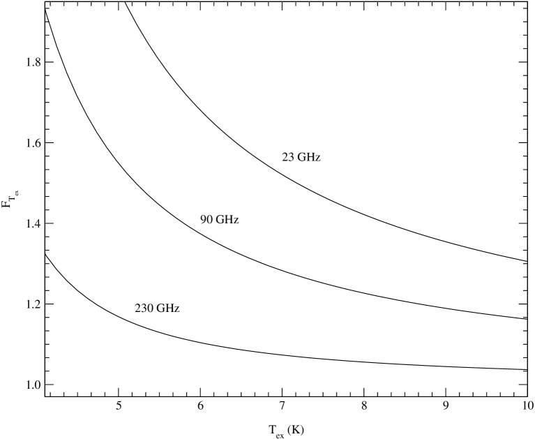
is the Planck function in temperature units. Note that when and , equation 5 becomes equation 3. However, for those regions where the temperature is low and with moderate densities, should be taken into account, especially for the low frequency transitions (see Fig. 7). should also be taken into account even for moderately small opacities: e. g., for .
The optical depth for each transition can be estimated if true column density, , is known. Since , the optical depth of a given rotational transition is given by:
| (8) |
Therefore, if the filling factor is included as an additional free parameter (with and ), the optical depth can be corrected whenever using the population diagram method.
To estimate the best set of solutions we calculated the value for each set of parameters, , and , taking into account the uncertainties (rms noise and calibration errors) in a similar way as that described by Nummelin et al. (Nummelin98 (1998)) and Gibb et al. (Gibb00 (2000)):
| (9) |
For those transitions undetected, the 3- upper limit for each transition was used whenever . The 1- uncertainties for and were obtained from the 68% confidence region of (e. g., Gibb et al. Gibb00 (2000)), which is enclosed within the interval, with where is the number of data points (including those undetected transitions that satisfy the aforementioned condition), is the number of free parameters (3 when the opacity correction is taken into account and 2 when optically thin emission is assumed), and equals to 2.3 and 3.5 for 2 and 3 free parameters, respectively (Lampton, Margon & Bowyer Lampton76 (1976)).
References
- (1) Anthony-Twarog, B. J. 1982, AJ, 87, 1213
- (2) Bergin, E. A., Ungerechts, H., Goldsmith, P. F., et al. 1997, ApJ, 482, 267
- (3) Blake, G. A., Sandell, G., van Dishoeck, E. F., et al. 1995, ApJ, 441, 689
- (4) Böhm, K.-H., Buehrke, T., Raga, A. C., et al. 1987, ApJ, 316, 349
- (5) Cao, Y. X., Zeng, Q., Deguchi, S., et al. 1993, AJ, 105, 1027
- (6) Choi, M., & Zhou, S. 1997, ApJ, 477, 754
- (7) Davis, C. J., Dent, W. R. F., & Burnell, S. J. B. 1990, MNRAS, 244, 173
- (8) Dent, W. R. F. 1997 in Poster Proceedings of the IAU Symposium 182, ed. F.Malbet, & A.Castets, 88
- (9) Dent, W. R. F., Cunningham, C., Hayward, R., et al. 1993, MNRAS, 262, L13
- (10) Dickens, J. E. & Irvine, W. M. 1999, ApJ, 518, 733
- (11) Dickens, J. E., Irvine, W. M., Snell, R. L., et al. 2000, ApJ, 542, 870
- (12) Eisloffel, J., Mundt, R., & Bohm, K. 1994, AJ, 108, 1042
- (13) Gibb, E., Nummelin, A., Irvine, W. M., et al. 2000, ApJ, 545, 309
- (14) Girart, J. M., Rodríguez, L. F., Anglada, G., et al. 1994, ApJ, 435, L145
- (15) Girart, J. M., Estalella, R., & Ho, P.T.P. 1998, ApJ, 495, L59
- (16) Girart, J. M., Estalella, R., Ho, P. T. P., & Rudolph, A. L. 2000, ApJ, 539, 763
- (17) Girart, J. M., Estalella, R., Viti, S., et al. 2001, ApJ, 562, L91
- (18) Girart, J. M., et al. 2002, in preparation (Paper II)
- (19) Goldsmith, P. F., & Langer, W. D. 1999, ApJ, 517, 209
- (20) Gonzalez–Alfonso, E., Cernicharo, J. 1993, A&A, 279, 506
- (21) Guilloteau, S., & Baudry, A. 1981, A&A, 97, 213
- (22) Haro, G. 1952, ApJ, 115, 572
- (23) Helmich, F. P. & van Dishoeck, E. F. 1997, A&AS, 124, 205
- (24) Herbig, G. H. 1951, ApJ, 113, 697
- (25) Hester, J. J., Stapelfeldt, K. R., & Scowen, P. A. 1998, AJ, 116, 372
- (26) Hogerheijde, M. R. & van der Tak, F. F. S. 2000, A&A, 362, 697
- (27) Kalenskii, S. V., Sobolev, A. M. 1994, Astro.Lett., 20, 91
- (28) Lampton, M., Margon, B., & Bowyer, S. 1976, ApJ, 208, 177
- (29) Langer, W. D., & Penzias, A. A. 1990, ApJ, 357, 539
- (30) Langer, W. D., & Penzias, A. A. 1993, ApJ, 408, 539
- (31) Linke, R. A., Frerking, M. A. & Thaddeus, P. 1979, ApJ, 234, L139
- (32) McMullin, J. P., Mundy, L. G., & Blake, G. A., 1994, ApJ, 437, 305
- (33) McMullin, J. P., Mundy, L. G., Blake, G. A., et al. 2000, ApJ, 536, 845
- (34) Morata, O., Girart, J. M. & Estalella, R. 2002, A&A, submitted
- (35) Nummelin, A., Dickens, J. E., Bergman, P., et al. 1998, A&A, 337, 275
- (36) Peng, R., Langer, W. D., Velusamy, T., et al. 1998, ApJ, 497, 842
- (37) Pratap, P., Dickens, J. E., Snell, R. L., et al. 1997, ApJ, 486, 862
- (38) Pravdo, S. H., Fegelson, E. D., Garmire, G., et al. 2001, Science, 413, 708
- (39) Raga, A. C., & Williams, D. A. 2000, A&A, 358, 701
- (40) Raymond, J. C., Hartmann, L., & Hartigan, P. 1988, ApJ, 326, 323
- (41) Raymond, J. C., Blair, W. P., & Long, K. S. 1997, ApJ, 489, 314
- (42) Reipurth, B. & Bally, J. 2001, ARA&A, 39, 403
- (43) Rodríguez, L. F., Curiel, S., Ho, P. T. P., et al. 1990, ApJ, 352, 645
- (44) Rodríguez, L. F., Delgado-Arellano, V. G., Gómez, Y., et al. 2000, AJ, 119, 882
- (45) Rudolph, A., & Welch, W. J., 1988, ApJ, 326, L31
- (46) Rudolph, A., & Welch, W. J., 1992, ApJ, 395, 488
- (47) Rudolph, A. L., Bachiller, R., Rieu, N. Q., et al. 2001, ApJ, 558, 204
- (48) Schwartz, R. D. 1978, ApJ, 223, 884
- (49) Schwartz, R. D., Cohen, M., Jones, B. F., et al. 1993, AJ, 106, 740
- (50) Taylor, S. D., & Williams, D. A. 1996, MNRAS, 282, 1343
- (51) Taylor, S. D., Morata, O., & Williams, D. A. 1996, A&A, 313, 269
- (52) Torrelles, J. M., Rodríguez, L. F., Cantó, J., et al. 1992, ApJ, 396, L95
- (53) Torrelles, J. M., Gómez, J. F., Ho, P. T. P., et al. 1994, ApJ, 435, 290
- (54) Turner, B. E. 1991, ApJS, 76, 617
- (55) Turner, B. E. 1994, ApJ, 437, 658
- (56) van Dishoeck, E. F., Blake, G. A., Jansen, D. J., & Groesbeck, T. D. 1995, ApJ, 447, 760
- (57) van Dishoeck, E. F. & Blake, G. A. 1998, ARA&A, 36, 317
- (58) Ungerechts, H., Bergin, E. A., Goldsmith, P. F., et al. 1997, ApJ, 482, 425
- (59) Viti, S. & Williams, D. A. 1999, MNRAS, 310, 517 (VW99)
- (60) Walmsley, C. M., Churchwell, E., Nash, A., & Fitzpatrick, E. 1982, ApJ, 258, L75
- (61) Wannier, P. G., Encrenaz, P. J., Wilson, R. W., & Penzias, A. A. 1974, ApJ, 190, L77
- (62) Wolfire, M. G., & Königl, A., 1993, ApJ, 415, 204