Gamma-Ray Imaging by Silicon Detectors in Space: the AREM Method
Abstract
We present the Agile REconstruction Method (AREM) for
-ray (30 MeV – 50 GeV) direction
reconstruction applicable to high-resolution Silicon Tracker
detectors in space. It can be used in a “fast mode”,
independently of Kalman filters
techniques, or in an “optimized mode”, including
Kalman filter algorithms for track identification.
AREM correctly addresses three points of the analysis
which become relevant for
off-axis incidence angles:
(1) intrinsic ambiguity
in the identification of the 3-dimensional
tracks; (2) proper identification
of the 3-dimensional pair production plane
and reconstructed direction;
(3) careful choice of an energy weighting scheme
for the 3-dimensional tracks.
We apply our method to simulated gamma-rays
in the AGILE detector. The excellent
spatial resolution obtained by the AGILE Silicon Tracker,
providing crucial analog information,
makes it possible to improve the
spatial resolution of previous detectors (e.g. EGRET) by
a factor of in containment radius at MeV.
In this
paper we present the results of our
3D-method for a selected sample of photon incidence angles and
energies. A more comprehensive and complete discussion including the
use of Kalman filter algorithms will be the subject of forthcoming
papers.
PACS: 95.85.Pw; 95.75.Pq; 95.55.Ka
Keywords: Gamma-ray Imaging Detectors; Angular Resolution
1 Introduction
High energy gamma-ray astrophysics is foreseen to be one of the more challenging fields of study in the coming years. Previous gamma-ray missions such as SAS-2 [1], COS-B [2], and especially the recent EGRET experiment [3, 4, 5] on the Compton Gamma Ray Observatory, left us with a large amount of exciting results and open questions. Indeed, of the nearly 300 gamma-ray sources detected so far only a small fraction () has been identified [5]. The discovery of gamma-ray blazars, pulsars, high-energy gamma-ray bursts (GRBs) and of a large amount of unidentified sources, many of which are strong high-energy transients, has provided clear evidence for the need of a next generation of gamma-ray experiments with increased field of view and improved angular resolution. In this context, the AGILE mission [6], planned to be operational during the year 2003, is integrated toward the GLAST mission [7], planned for the year 2006. In this paper, we consider the EGRET spark chamber experiment as the direct AGILE predecessor, and we will refer to it for comparisons.
We recall here that AGILE (Astro-rivelatore Gamma a Immagini LEggero)111 More information about the project can be found at the site: http://www.ifctr.mi.cnr.it/Agile. is a Small Scientific Mission of ASI (Agenzia Spaziale Italiana) with a tracking system based on the state-of-the-art Silicon strip technology [6, 8]. The AGILE GRID (Gamma-Ray Imaging Detector) consists of a Silicon-Tungsten Tracker, a Cesium-Iodide Mini-Calorimeter and a segmented Anticoincidence system of plastic scintillators and is sensitive to 30 MeV - 50 GeV photons. Thanks to the fast readout electronics and to the segmented Anticoincidence system, AGILE will have, among other features, an unprecedently large field of view (FOV sr), larger than previous gamma-ray experiments by a factor . Furthermore the Silicon Tracker has a very good intrinsic spatial resolution, comparable or even less than the microstrip pitch m, by using the analog information on the released charge distribution between strips. For comparison, we recall that the EGRET spark chamber wire spacing was equal to m.
The AGILE goal is to obtain the best sensitivity ever reached for off-axis events (up to ), and an on-axis sensitivity comparable to that of EGRET, despite the smaller dimensions and effective area. Therefore, the optimization of the angular resolution algorithms becomes a crucial point to fulfil the mission scientific objectives.
The -ray photon direction reconstruction is based on the physical process of pair production, and is obtained from the identification and the detailed analysis of the electron/positron tracks stemming from a common vertex. The direction reconstruction should take into account the effect of multiple Coulomb scattering and the distribution of the total energy of the incident photon between the particles. Until now, this was done by analyzing separately the two tracks projections in the ZX and ZY views. We will show in section 2 that the “2-D projection method” is a good approximation only for nearly on-axis events, but it induces two kinds of systematic error in the -ray direction reconstruction for off-axis events because of the intrinsic ambiguity in the proper identification of 3-D tracks and of the problem of the correct reconstruction of the true 3-D photon direction. Finally, we point out the importance of the choice of a proper track weighting scheme.
In this paper we emphasize that, contrary to previous -ray experiments, the simplified 2-D projection method would not be a good approximation for AGILE because of its large field of view and very good intrinsic spatial resolution. As we discuss in the next section, the first source of error follows from the ambiguity in the association of coordinate pairs corresponding to the hits in the Tracker in the two orthogonal ZX and ZY views. This ambiguity can be resolved in all those cases in which one of the two tracks becomes distinguishable from the other in both views of the Tracker, as for example when it stops or exits the Tracker, or when it suffers a more significant multiple scattering. Regarding the second point, we notice that in general, and expecially for off-axis events, the 3-D reconstruction is not equivalent to the composition of reconstructed directions in each projected view. So we are forced to consider an intrinsically three-dimensional strategy in order to reconstruct the true incident photon direction. The third point keeps into account the fact that, in general, the photon energy is not evenly divided between the two pair particles. It turns out that the incident photon direction is closer to that of the most energetic particle, and an “energy-weighted” direction reconstruction is necessary.
The AGILE REconstruction Method (AREM) presented in this paper, provides a general baseline, to be optimized for each particular -ray instrument, to keep into account these three points of the analysis.
2 The AREM method
2.1 The conversion plane problem
Let us first illustrate and discuss the conversion plane problem in the simplified case of an even energy sharing between the electrons and positrons i.e., when the photon direction coincides with the bisector. We restrict the discussion to the idealized case of absence of -rays or other secondaries in the Tracker. In general, each Si-Tracker plane of a -ray detector is composed of a converter layer and by two orthogonal strips layers. Charged particles entering the Tracker will produce an electric signal in the front-end electronics which would correspond to the hit readout strips in the two active X and Y layers. As long as a single charged particle crosses the Tracker, this signal will identify a unique point in 3-D space for each hit plane. However, when two separated particles hit simultaneously the active layers (as in the case with pairs) the signal could correspond to two possible couples of points in 3-D space, as shown in Fig. 1.
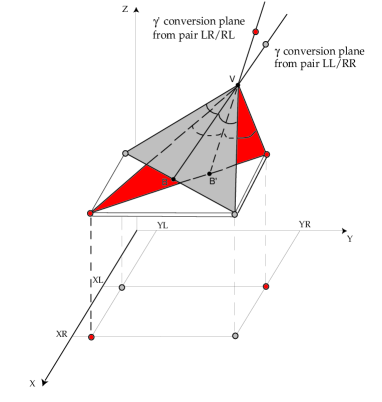
The two possible couples of points are: pair LL/RR = , open symbols in the figure, or pair LR/RL = , filled symbols. This gives rise to an intrinsic ambiguity in the conversion plane identification. In terms of projected views this “conversion plane problem” can be phrased as: “Does the track to the left in the ZX view correspond to the left track in the ZY view - pair LL/RR? Or does it correspond to the track to the right - pair LR/RL?”.
Note that for on-axis events the “pyramid” in Fig. 1 becomes isosceles and the conversion plane problem apparently disappears, since both alternatives - pair LL/RR or LR/RL - would lead to the same bisector. However, we recall that we are considering here the particular and unrealistic case of an even energy sharing. In general the photon energy is not evenly divided between the two particles (see Sect. 2.3), and the photon direction does not coincide with the bisector. Hence the ambiguity for the identification of the “energy-weighted” reconstructed direction applies also to on-axis events.
AREM algorithms solve the intrinsic ambiguity in the identification of the 3-D tracks by identifying a primary and a secondary track in both ZX and ZY views. The primary track is defined as that one carrying most of the incident energy, and subject to less multiple scattering. In practice, we identify the primary track as the one for which (starting from the third plane) the quantity is on average minimized. This means that the primary track should have the smallest mean distance between the selected clusters and the position obtained by extrapolation of the trajectory from the previous planes. The 3-D primary track is then obtained by associating the primary track in the ZX view with the primary track in the ZY view (analogously for the secondary one).
2.2 The projection problem
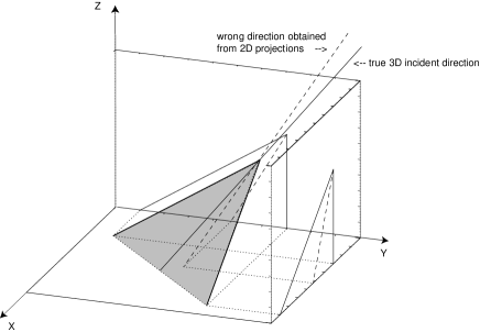
According to the simplified 2-D projection method, the first step is to identify the two projected tracks in each view. The following step is to take their (in general weighted) bisectors and compose them to obtain the reconstructed gamma direction. This procedure is not correct: the true 3-D bisector has ZY and ZY projections which do not correspond to the two bisecting lines in each view. This is illustrated in Fig. 2. The only case in which this equality holds true is for on-axis events. As shown in ref. [9], this systematic effect increases for increasing off-axis angles and large opening angles up to values of , hence the 2-D projection method is not acceptable for AGILE and similar detectors222We warmly thank the EGRET collaboration, and in particular D.L. Bertsch and D. Thompson, for allowing us to perform a test of our reconstruction algorithms on their calibration data. In the case of EGRET data this systematic error can be considered almost negligible, since it is hidden by the relatively low spark chamber intrinsic resolution..
The proper identification with AREM of the 3-D pair production plane and photon direction reconstruction can be obtained by several completely equivalent geometrical methods, such as: spherical triangle formulae, normalized 3-D vector components, or double rotation of reference system. In the following we use the latter method.
2.3 Track weighting scheme
In the pair production process the total energy of the incident photon is split between the particles. We recall that the probability distribution of having an electron, or a positron, with energy when the primary photon has energy , is almost flat in the “low” energy range MeV. However, for increasing incident energy it is more and more probable that one of the two secondary particles carries most of the total energy (see for example Fig. 2.19.2 of ref. [10]). The RMS emission angle between the original photon direction and the direction of the electron, or positron, roughly depends on the inverse of the photon energy [10]: . This implies that for most events in the AGILE energy range the main information on the original photon direction will be carried by the most energetic particle. It follows that the choice of a proper track weighting scheme to keep into account the energy distribution between the particles plays a fundamental rôle in the angular reconstruction algorithms.
Can we obtain a satisfactory track energy estimate relying mainly on Tracker data? Multiple scattering spreads the information on the original particle directions, but on the other side it can be exploited to obtain a track energy estimate. According to the Molière theory [11], the small planar deflection angle of multiple scattering has an approximately Gaussian distribution with high tails (for a detailed analysis see also ref. [12]). The Molière formula for the RMS scattering angle can be written as:
| (1) |
where is the thickness of the scattering medium in radiation lengths. In our case, the relation between particle momentum and energy is: , and the velocity is such that: , since we consider . There is then an (approximate) inverse relation between particle energy and RMS deflection angle:
| (2) |
where here is the angle between the considered track and the vertical axis. This means that the most energetic particle suffers less multiple Coulomb scattering.
The AREM choice of weighting scheme is based on Molière multiple scattering theory. In principle, each 3-D track should be weighted by its energy to some power. According to eq. (2), for each projected track we define a weight as:
| (3) |
where is a parameter to be optimized for each particular -ray instrument. In practice, the quantity is used to estimate the RMS multiple scattering angles , and hence the particle energies .
2.4 The AREM flow
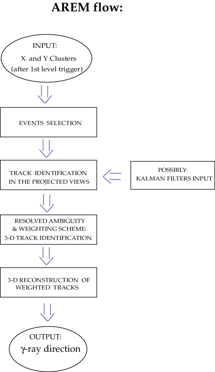
Summing up, we show in Fig. 3 the general flow chart for the software corresponding to the AREM method described in the previous subsections.
3 Applications to the AGILE Tracker
3.1 Instrumental and geometrical set-up
The AGILE baseline configuration [6] is the following:
-
-
Silicon Tracker: the AGILE Tracker consists of 14 detection planes cm2 total area with cm interplane distance. Each plane is composed by two layers of microstrip Silicon detectors with orthogonal strips (X and Y view). The first 12 planes, starting from the top, have also a Tungsten conversion layer each, with thickness equal to radiation length. The last two planes have no Tungsten layers, since the readout trigger requires at least three Si-layers providing signals. The active area of the Si-detectors is made of tiles where microstrips of pitch of are implanted. Only half of the strips in every tile are readout strips. However, it is possible to detect a signal even if the particle hits a “floating” strip, by taking into account the effect of the capacitive coupling between contiguous strips333The “floating strip” configuration has been chosen to achieve an excellent spatial resolution while keeping under control the number of readout channels and hence the detector power consumption..
-
-
Mini Calorimeter: it consists of two orthogonal planes, each containing 16 CsI bars, for a total radiation length of .
-
-
Anticoincidence System: it is made of lateral segmented Plastic Scintillator planes composed of 3 panels for each Tracker side and of a top plane of thickness of cm.
3.2 Monte Carlo simulations
The Monte Carlo simulations of AGILE performances are done with the GEANT 3.21 code [14]. The GEANT package reproduces all possible interactions of radiation and particles through matter, such as pair production, multiple scattering, Compton scattering, etc.
In the case of the AGILE Tracker, CERN testbeams indicate that the experimental uncertainty in the identification of the position of a cluster of adjacent strips providing signal on a track can be reduced at the level of m [8]. This result is achieved by using the analog readout which gives information on the charge distribution released in the Si-microstrips, and the floating strip configuration. However, since the experimental validation of the parametrization of the capacitive coupling effect at large off-axis angles is still in progress, in order to implement and test the AREM method we use here a simplified version of the AGILE simulation code, originally developed by the AGILE simulation software group [13]. In this simplified model, which does not yet include capacitive coupling and floating strips, all the strips are readout strips and the digitization uncertainty is simply determined by the pitch. This detector model is very accurate and detailed enough to be fully suitable for our analysis.
The simulated events are characterized by the incident photon energy, , and by a fixed incident direction ( , ) with respect to the detector sistem of reference. The algorithms which generate flux sources originating from a fixed direction are optimized to correctly simulate a plane wave front from an infinite distance [13].
3.3 Analysis of simulated events
From our Monte Carlo simulations, we obtain the complete detector response to the incident -ray flux, at several energies and incident angles. We recall that the standard data analysis based on Kalman filter algorithms [15], which make use of the information from all hit planes, is optimized for charged particle track identification, but not specifically for -ray direction reconstruction. Hence, as a first step to test our reconstruction method, we perform an analysis of the first n-Planes Resolution, i.e. using only information from the first hit planes, for which the information on the original photon direction is less disturbed by multiple scattering. In this preliminary study we present in particular our results regarding AREM 2PR and 3PR (2PR = two planes resolution, 3PR = three planes resolution).
In view of our introductory discussion, multiple scattering has a two-fold effect: it disperses the information on the original direction of the particle going through subsequent converter layers; on the other hand, it can be exploited to obtain a particle energy estimate. Integrating AREM with the high efficiency algorithms based on the Kalman filters will be the next step to improve the energy determination and weighting scheme, and to further optimize the AGILE angular resolution [16].
3.4 Event selection
According to AGILE Level-1 trigger conditions, there must be at least three consecutive Tracker planes which give a signal in both views444 The actual on-board first level trigger is given by the coincidence of 3 out of 4 consecutive Tracker planes, to take into account the possibility of one-plane failure. Simulations show that the final difference on the total number of rejected events at subsequent trigger level is of order of [13].. With respect to trigger Level-1, we perform a further event selection by asking that accepted events show only one cluster of strips on the first hit Tracker plane in both views. This amounts to require that it be possible to identify a “clean” conversion vertex in both Tracker views. We also require no more than two clusters on the second hit Tracker plane, always in both ZX and ZY views. In such a way we reject all events with spurious hits on the second plane, i.e., we require a “clean” second plane. We do not impose any further conditions on the third and subsequent planes.
3.5 Two plane resolution
We have analized first the so-called two plane resolution (2PR) of the Tracker, which takes into account only the information coming from the first two hit planes. The 2PR gives no further information on the deviation from the initial track direction obtained from the firts two planes and we are forced to neglect multiple scattering and energy distribution effects. We can only take a random choice regarding the conversion plane problem described in Sect. 2.1, and we get a coordinate ambiguity error for about of the photons. Regarding the projection problem described in Sect. 2.2, we can still utilize the 3-D method to guarantee the proper reconstruction of the bisector.
3.6 Three plane resolution
We then include in our analysis the information coming from the third hit plane. For the three plane resolution (3PR), the event selection criteria remain the same as in the 2PR case, and are the ones described above. This implies that the efficiency of the two reconstruction algorithms are equal. In this case we are in the condition to follow the complete AREM flow and to correctly address the intrinsic track ambiguity and the projection problem. Having identified a primary and a secondary track, we can assign a weight to each track as described in Sect. 2. In the following, we chose as a particular weighting scheme: , i.e. we set in eq. (3), and the track energy is estimated from the inverse of square root of the variance of the track linear fit.
3.7 Results
In Fig. 4 we show the 3-D integral Point Spread Function (PSF) for events at , for the energies , , and . In that figure we compare the PSF profiles obtained by 2PR and 3PR. The 3PR containment radius (c.r.) is systematically better than the 2PR one for . Since the efficiency of the two reconstruction algorithms is the same, the improvement of the angular resolution obtained with AREM 3PR is in part due to the solution of the coordinate track ambiguity and of the adopted weighting scheme. For the event set considered in Fig. 4 this effect ranges from up to at higher energy. This is also shown in Fig. 5, were we compare the 3-D PSF at c.r. as a function of energy in the case of EGRET on-axis and of AGILE 2PR and 3PR at incidence angle .
The comparison between the results obtained with the 2-D and 3-D reconstruction methods, both applied to the 3PR algorithm, is shown if Fig. 6 which summarizes the effect of AREM on the AGILE resolution at incidence angle .
In Fig. 7 we report the final results obtained with AREM 3PR for AGILE angular resolution near on-axis and at off-axis. The efficiency of the AREM 3PR reconstruction (same as 2PR) is shown in Fig. 8 and it is compatible with the one obtained by EGRET [3]. Summing up, we find that the AGILE 3PR resolution is better than that of EGRET by a factor of above 400 MeV. These results are remarkable considering the fact that in this preliminary study we are disregarding all the information on the following hit planes, and that we make no use yet of the Mini-Calorimeter information.
4 Conclusions
We presented here the Agile REcontruction Method and the results of a preliminary study of its application using only information from the first three hit planes, for which the information on the original photon direction is less dispersed by multiple scattering. The preliminary results of AREM 3PR provide a satisfactory PSF, that turns out to be better than that of EGRET by a factor of at energies above or equal MeV, up to incidence angles of off-axis. We expect to improve this result by integrating the AREM method with the standard Kalman filter algorithms, to take properly into account the information from all hit planes, and with the Mini Calorimeter data, in order to optimize the track energy determination and the AREM weighting scheme [16]. Moreover, a further improvement of the AGILE PSF should be obtained by applying the AREM method to a model of the AGILE instrument which includes the forthcoming results of a more accurate experimental study of the charge deposition in the Si-microstrips. This analysis will allow an optimal use of the analog readout, which is one of the main characteristics of the AGILE Tracker.
ACKNOWLEDGMENTS
We thank D.L. Bertsch and D. Thompson for many discussions and collaborative work on EGRET calibration data. We also thank V. Cocco, A. Giuliani, F. Longo, S. Mereghetti, A. Pellizzoni, S. Vercellone and D. Zanello for many interesting discussions and scientific exchanges. We wish to thank the Astroparticle Physics WIZARD Group and INFN Section of Roma II for kind hospitality. C.P. thanks in particular M.P. De Pascale for useful comments after a careful reading of the manuscript, A. Morselli for collaboration at the initial stage of this work and P. Picozza for having set up the Cosmic-Ray research area at the “ Tor Vergata” University of Rome.
Work carried out under the auspices of the Agenzia Spaziale Italiana.
References
- [1] C.E. Fichtel et al., Astroph. J. 198 (1975) 163.
- [2] B.N. Swanenburg et al., Astroph. J. 243 (1981) L69.
- [3] D.J. Thompson et al., Astroph. J. Suppl. 86 (1993) 629.
- [4] C.E. Fichtel et al., Astroph. J. Suppl. 94 (1994) 551.
- [5] R.C. Hartman, et al., Astroph. J. Suppl. 123 (1999) 79.
- [6] M. Tavani et al., Proceedings of the GAMMA 2001 Symposium, to be published by AIP, and preprint (2001) in preparation, to be submitted to Nucl. Instr. and Meth. A.
- [7] P. Michelson, Proceedings of the GAMMA 2001 Symposium, to be published by AIP.
- [8] Barbiellini, G. et al., Proceedings of the GAMMA 2001 Symposium, to be published by AIP, and preprint (2001) submitted to Nucl. Instr. and Meth. A.
- [9] A. Giuliani, “Studio e Ottimizzazione della Risoluzione Angolare del Telescopio Spaziale per Astronomia Gamma AGILE”, Laurea Dissertation, Università degli Studi di Pavia, (2001).
- [10] B. Rossi, “ High-Energy Particles”, Prentice-Hall, New York (1952).
- [11] G. Molière, Z. Naturforsch. 2a (1947) 133 and 3a (1948) 78.
- [12] D.L. Bertsch, Nucl. Instr. and Meth. 220 (1984) 489.
- [13] V. Cocco, F. Longo and M. Tavani, AGILE Internal Tech. Note, AGILE-SIM-TN-001, Issue n.2 (2000), and preprint (2001), to be published in Nucl. Instr. and Meth. A.
- [14] GEANT Detector Description and Simulation Tool, 1993, CERN.
- [15] R. Frühwirth, Nucl. Instr. and Meth. A 262 (1987) 444.
- [16] C. Pittori et al., Proceedings of the GAMMA 2001 Symposium, to be published by AIP, and preprint (2001) in preparation.


