A ballistic bow shock model for jet-driven protostellar outflow shells
Abstract
We analyze the dynamics of the shell produced when a bow shock from a collimated jet propagates into the surrounding medium. Under interstellar conditions, the shock is radiative, and a ballistic approximation for the shell flow is appropriate beyond the working surface where the jet impacts its surroundings. The solution is then determined by the ambient and jet densities and velocities and by the momentum impulse applied in the working surface. Using estimates for these impulses (confirmed by separate numerical simulations), we obtain solutions for the shell structure, and for the range of velocities in the shell at any point. We provide predictions for the position-velocity and mass-velocity relations expected for plane-of-sky bow-shock shells, and for the bulk shell properties. In a companion paper, we show that these analytic solutions are in excellent agreement with the results of direct numerical simulations. We argue that classical molecular (CO) outflows cannot be purely jet-driven, because the bow-shock shell solutions are much too elongated compared with observations. Finally, we suggest that the “spur” structures seen in position-velocity diagrams of observed molecular outflows are the manifestation of internal bow shocks which may be fit with our simple dynamical models.
1 Introduction
Bipolar molecular outflows appear to be an inevitable byproduct of low-mass star formation: essentially every pre-main sequence star that is still surrounded by substantial molecular material shows signs of outflow in the molecular line channel maps. Although there is considerable variety in the structure and kinematics of these outflow lobes (including a great deal of irregular morphology) many of these lobes take the shape of hollow shells (e.g. Moriarty-Schieven et al (1987)). In cases where optical or infrared Herbig-Haro jets are also seen, the molecular shells are approximately centered on the axes defined by these jets. Recent reviews of the molecular outflow phenomenon are found, e.g., in Bachiller & Tafalla (1999) and Richer et al (2000).
Two basic models have been advanced to explain how molecular shells are driven from young stellar objects (YSOs). In the first model, the outflow is produced by a wide-angle wind directly sweeping up surrounding ambient material (see discussion and original references in Shu et al. (2000)). In the second model, the outflow represents an expanding bow shock in the ambient medium produced by the impact of a narrow, dense jet (see e.g. the semianalytic models of Masson & Chernin (1993); Raga & Cabrit (1993), and the simulations by Chernin et al (1994); Smith, Suttner, & Yorke (1997); Suttner et al (1997); Downes & Ray (1999)). In the wide-angle wind scenario, outflows are a purely momentum-driven phenomenon; the thermal pressure of the gas is taken to be negligible. In the jet-driven scenario, on the other hand, the transverse (i.e. perpendicular to the jet axis) expansion of a bow shock to create an outflow shell depends crucially on the action of pressure in the head of the jet. The two models thus differ both in their assumptions of the nature of the primary wind, and in the physical processes involved in the ambient medium interaction that produces the outflow.
In following a fully deductive theoretical approach, one would first determine the nature of the primary wind that is expected to form, and then analyze how it acts on its surroundings to produce outflows. However, a more inductive approach – in which clues to the nature of the primary wind may be gleaned from analyzing the “secondary” outflow kinematics – can often aid progress in circumstances, such as the present one, where the first-principles approach involves major theoretical challenges. In particular, although there is significant theoretical consensus that the primary winds from low mass YSOs are magnetocentrifugally driven, there remain unresolved questions about the relative importance of winds driven from the interaction region between a stellar magnetosphere and the disk (x-winds; Shu et al. (2000) and references therein), and winds arising from a larger range of radii in the disk (disk winds; Königl & Pudritz (2000) and references therein).
In fact, neither the x-wind nor the disk-wind model would produce the sort of spatially-isolated “pure jet” generally taken as the input to a jet-driven outflow calculations, because such a jet would be highly magnetically overpressured relative to the ambient ISM at large distance from the source (Ostriker, 1997; Kim & Ostriker, 2000). Thus, at least the surface layers, and possibly the entirety, of either sort of wind would expand to produce a gradient of matching the low pressure of the ISM on the outside and the high pressure of the wind core on the inside. Shu et al. (1995) show that a radially-expanding, magnetically force-free () wind with density stratified as is a self-consistent solution to the asymptotic state of x-winds; similar “fully-expanded” magnetically force-free solutions may be found for the asymptotic state of disk winds (Ostriker, 1997, 1998; Matzner & McKee, 1999). Another outcome potentially could involve only partial expansion of the wind, leaving a highly overdense core and strongly stratified surroundings. Whether a wind attains full or only partial expansion may depend on its boundary conditions and stability properties (e.g. Kim & Ostriker (2000)), with no comprehensive theoretical predictions available at present.
Thus, although there is not yet a complete theoretical catalog for the range of structure possible for primary winds, first-principles theoretical considerations do suggest that completely isolated jets would not occur in general. Instead, the primary wind in the “jet-driven” outflow scenario is more properly thought of as a more extreme (in its degree of central concentration) version of the radially flowing primary wind invoked in the wide-angle wind model. “Jet-driven” outflows, then, would arise if the circumstances were such as to produce a primary wind with a very dense core (the optical “jet”) surrounded by an (optically unseen) envelope in which the density (and magnetic pressure) falls off very steeply (e.g. faster than an power law). With this modified view of the nature of primary wind, any model should contain a wide-angle wind at some level. Two classes of outflow-driving scenarios might then contrast “wind-swept shell” models vs. “bow shock shell” models based on the relative importance of transverse bulk flow momentum in the primary wind (i.e. ram pressure), vs. transverse thermal pressure gradients created in the shock, in producing the expansion of the outflow away from the central axis.
The wind-swept shell formalism was first presented in the x-wind context by Shu et al. (1991), and later updated to reflect the strong polar- and equatorial- stratification subsequently found to arise, respectively, in magnetic wind and protostellar core solutions (Li & Shu, 1996). Matzner & McKee (1999) recently extended the wind-swept shell analysis to more general classes of primary winds. In all of these models, the primary wind is assumed to be radially outflowing, and the interaction with the ambient medium is treated as a local mass- and momentum- conserving process. With these idealizations, together with the assumption that the radial variation of the density profile in the ambient core follows an power law, one may obtain analytic solutions for the dynamics of wide-angle-wind driven outflow shells in which the shell velocity is steady but depends on the polar angle. These models have proven very successful at explaining the shapes and kinematics of many – but not all – of the features seen in the outflows from young stars (Li & Shu, 1996; Nagar et al, 1997; Ostriker, 1997; Matzner & McKee, 1999; Lee et al., 2000a). In particular, several outflows show evidence of “convex spurs” in position-velocity space, in which transverse velocities of portions of the outflow increase with distance from the source. In configuration (position-position) space, the corresponding outflow shell closes toward the axis with increasing distance, with the appearance of a bow shock (Lee et al., 2000a).
In this paper, our goal is to develop an analytic model for protostellar outflow shells in the situation complementary to that addressed by Shu et al. (1991): namely, when the transverse radial forces are dominated by pressure gradient forces near the the head of the jet (or, more properly, jet-like wind), rather than by ram pressure throughout the body of an extended wind. To this end, we construct a simple dynamical model of jet-driven bow shocks under interstellar (strongly-cooling) conditions. The model solutions depend only on four basic properties describing the jet and ambient medium (the jet speed and radius, and the jet and ambient densities), and on the cooling function for shocked gas. We provide analytic solutions for the shell shape and velocity fields in this model, and use these results to develop solutions for two kinematic diagnostics often used in analyzing observations of outflows – the position-velocity and mass-velocity relations. We also provide expressions for “bulk” properties of jet-driven outflow shells (lobe aspect ratio, total mass, momentum component ratios) in terms of the system’s physical parameters. In the companion paper (Lee et al., 2000b), we compare the results from the analytic model of this paper with the results of direct numerical simulations of bow shocks driven by model protostellar jets. There, we also compare the results of wind-swept shell “snowplow” models with the results of numerical simulations where the input wind has an extended (wide-angle) density and velocity distribution.
2 Analysis: bow shock shape and shell velocities
The interaction of a supersonic jet with its surroundings drives a bow shock into the ambient medium; under uniform conditions with time-independent jet properties, the bow shock preserves its shape and advances along the jet axis at a speed . Figure 1 shows a schematic diagram of our model for shell formation, viewed from the bow shock frame moving at velocity with respect to the observer’s frame. We adopt a cylindrical coordinate system. In this diagram, the working surface (“WS”) is the region where the jet itself collides and interacts with the ambient medium: hot, shocked jet material processed through a jet shock (at the left of the WS) abuts hot, shocked ambient material processed through the bow shock (at the right of the WS) at a contact discontinuity (in the center of the WS). Due to thermal pressure gradient forces perpendicular to the jet axis, material is expelled radially from the WS. This flow expands away from the jet, and drives a bow shock into the ambient medium. The ambient material, moving backward in the frame of the bow shock, collides with the shell of transversely-flowing matter and deflects it rearward (in the direction). The swept-up ambient material augments the flux of matter in the transversely-expanding flow.
The shape of the shell and simple kinematic diagnostics can be derived by solving for the shell dynamics in the ballistic limit, i.e. with pressure forces ignored subsequent to an initial impulse. 111This approximation is valid because the shock (away from the jet head) is sufficiently oblique that the post-shock pressure is is relatively low, and is further reduced by the strong cooling present under interstellar (compared to extragalactic) conditions. In the bow shock frame, the ambient material flows into the shock with velocity . The increase in the mass flow of shocked gas per unit length transverse to the jet axis is
| (1) |
where is the density of the ambient material. Similarly, the increases per unit transverse length in the axial-direction and radial-direction flows of momentum (, ) are
| (2) |
and
| (3) |
Integrating equations (1), (2) and (3), we have
| (4) |
| (5) |
| (6) |
where is the radial width of the WS where the shell emerges. , and are the initial mass, longitudinal momentum and transverse momentum flows input from the WS into the shell.
If a negligible portion of the shocked-gas mass and momentum are lost from the inner shell into the cocoon, then the total shell mass flow and momentum flow at a distance are , and . In the absence of shell mass losses, the velocity field direction within the shell must be locally parallel to the shell surface (the bow shock), although there may be gradients in the magnitude of the velocity across the shell thickness perpendicular to the shell surface. Under this assumption, the ratio is the same throughout the shell thickness at any , and equal to the slope of the shell’s surface. Since is constant across the shell thickness, the ratio of the total momentum flows and also gives the local slope of the shell surface (here the integral over denotes summation across the shell thickness). The shape of the shell can thus be derived by integrating
| (7) |
The locus of the bow shock/outflow shell is therefore given by
| (8) |
with at .
With expression (8) giving the locus of the outflow shell, we may now turn to the distribution of velocities within the shell. Consider first the limit in which the material added to the shell at any point mixes instantaneously with all the material already flowing along in the shell at that position. If the “new” and “existing” momentum were to mix thoroughly, then there would be no velocity gradients across the thickness of the shell. The velocity of shell material in the shock frame would be equal to the mean value at any point, given by
| (9) |
| (10) |
In the observer’s frame, transforms to
| (11) |
In particular, the shock-frame shell velocities just outside the WS are and , where the latter transforms to in the observer frame.
In the simulations presented by Lee et al. (2000b) in a companion paper, we find that the newly swept-up ambient material does not in fact fully mix with the material already in the shell. We are thus led to analyze the opposite limit from the above: no mixing between “new” and “existing” shell material. Consider first the outer surface layer of the shell consisting of the material that has most recently been swept up by the advancing bow shock. If the ambient material shocks strongly upon colliding with the shell, the postshock velocity of the newly swept-up material in the shock frame at any point is just the component of preshock velocity parallel to shell surface. With the angle between the shock normal and (see Fig. 1), the velocity of the newly-shocked material is given by
| (12) |
in the shock frame. In the observer’s frame, transforms to
| (13) |
The shape of the shell is determined by the total momentum flows only, independent of whether momentum is mixed within the shell or not. Therefore, substituting from equation (7) for , we find the velocity components of the newly swept-up material in the observer’s frame are
| (14) |
and
| (15) |
In the limit of negligible mixing, the magnitude of the momentum of any fluid element (and hence its speed) would remain unchanged as it flows outward along the bow-shock shell, because the impact of new material to the shell applies a force transverse to its surface (but not along it) as it shocks. With a force perpendicular to (which is parallel to the shell surface), the magnitude would not change, but the direction would rotate always remaining parallel to the shell surface. Thus, at the point , the material that entered the shell from the WS with speed would have shock-frame component velocities and at the position , with the latter transforming to in the observer’s frame. Similarly, the material that entered the shock at with post-shock speed would have components at position given by and , with the latter transforming to in the observer’s frame; here . Since is a secularly increasing function of , increases from to and decreases from to as increases from just outside to , for fixed . That is, the more recently a fluid element has joined the shell flow from the ambient medium, the larger its transverse and the smaller its longitudinal velocity would be at any point , in the absence of mixing.
To obtain explicit solutions, we now relate the shell input flows , and to more basic quantities characterizing the jet and ambient medium. First, we note that for a strong shock, the bow shock speed is related to the jet speed and ratio of jet- to ambient- density by . The radius of the WS can be approximated as . As shown in Figure 3 of Lee et al. (2000b), only shocked ambient material flows into the shell from the WS; therefore the mass flow is just equal to the flow of ambient material into the WS, . The input longitudinal momentum flow , because in the shock frame, the ejected flow from the WS has no preferred forward or backward direction.
Estimating the transverse momentum flow is slightly more subtle. Just inside the bow shock, the shocked ambient gas cools rapidly down to K, after which point the radiation slows because the cooling curve drops precipitously as the gas recombines. The shocked flow from the ambient medium interfaces (in a contact discontinuity) with the shocked jet gas at the center of the WS; in a steady state and with negligible mixing, all of the streamlines entering the WS from either side must bend away from the axis and exit on their respective sides of the bow shock/jet shock interface. The pressure is highest closest to the axis, with the transverse pressure gradient accelerating gas radially to eject it from the sides of the WS.
The ejection velocity from the WS must be of order the sound speed at the temperature K. To see why this is so, consider adiabatic flow with starting from low velocity and high pressure , and accelerating by pressure gradient forces until the ram pressure far exceeds the thermal pressure. By Bernoulli’s theorem, which demands the constancy of , the ejection speed would thus be , where is the isothermal sound speed at the initial temperature of the flow. Here, is the mean molecular mass, which we take as for neutral gas. 222Falle & Raga (1993) and Biro & Raga (1994) have made related arguments, confirmed by simulations, for estimating the speed of material ejection from internal shocks in jet beams. To the extent that cooling reduces the enthalpy term, and that the flow does not reach the maximum possible speed, the outflow velocity from the working surface would be somewhat lower. We therefore expect a transverse momentum flow from the WS of order , where the value of at K is . To test this estimate, we have directly measured the transverse momentum flux in our simulations with varying and , and also fit the shell shapes and kinematics parameterized by the momentum flux (see below and Lee et al. (2000b)). Writing , we have found that for jet radii and velocities in the ranges and . These values of are slightly larger than the above estimate; the difference may be accounted for by the facts that (i) the pressure of the shocked jet gas adjoining the shocked ambient gas within the WS helps in part to accelerate the shell, and (ii) the ambient material just outside the WS also passes through a relatively perpendicular (rather than oblique) shock, maintaining a non-negligible pressure in the shell at radii slightly larger than and correspondingly raising the total transverse momentum flux delivered to the bow shock shell.
With the above substitutions for , , and , we find so
| (16) |
and
| (17) |
The components of the mean shell velocity and newly-shocked velocity in the observer’s frame are given by
| (18) |
| (19) |
| (20) |
and
| (21) |
The shape is given by
| (22) |
which at large distance from the head of the jet approaches a cubic law 333A similar asymptotic law was previously obtained by Wilkin (1996) in his solution for the shell shape in the “tail” of a stellar wind bow shock for a star moving with constant velocity through a uniform medium. This is consistent with expectations that the specific geometry of the transverse momentum source is not important for the far-field solution., .
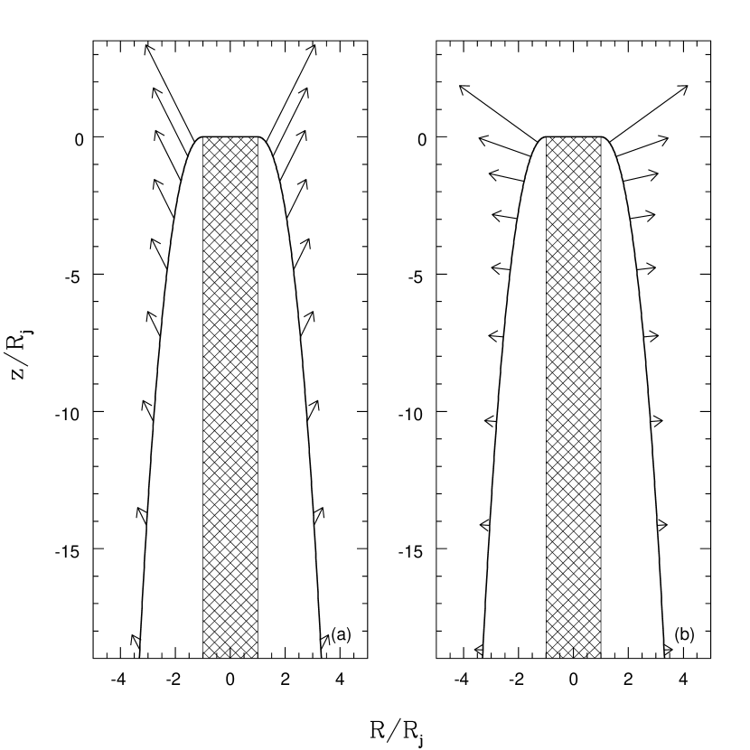
In Figure 2, we give an example of the shape of the bow shock shell, together with the observer-frame vector fields for the mean shell velocity and the velocity of the newly swept-up shell material . For this figure, we take the value of the ratio ; for the range of observed jet velocities, the range of this ratio would be . In Figure 3, we display the values of the various shell velocity components as seen from the observer frame, for the same model.
At large , the component velocities of the newly-added material approach and . That is, the transverse velocity of newly-added material is the same as the existing mean value of the transverse velocity, while the longitudinal velocity of newly-added material is smaller than the mean longitudinal velocity by the inverse of the large factor . The ratio of the mean velocity components has a small, constant value . The newly-shocked material, on the other hand, has an increasingly large ratio of transverse- to longitudinal- velocity as the distance from the head of the jet increases, .
Near the head of the jet (), the longitudinal speeds and both approach the bow shock speed . The average transverse speed in the flow approaches , while the transverse speed of newly swept-up material reaches a local maximum value of near and then declines to zero at .
The velocity , which would describe the transverse motion of the material initially expelled from the WS in the absence of any shear mixing with latterly-added fluid elements, remains close to both and far from the head of the shock (large ). Its longitudinal counterpart, , however, remains much larger than both of the velocities and that describe the mean longitudinal motion and the longitudinal motion of newly-added material.
In the shock frame, all of the transverse momentum in the shell is provided by the initial impulse at the jet head (by assumption). The transfer of portions of this transverse momentum to the newly-shocked material is mediated by pressure, with the egalitarian result that the transverse velocity of newly swept-up material is nearly the same as the existing transverse velocity in the shell. Longitudinal momentum, on the other hand, is carried into the shell by every ambient mass element that is swept up by the advancing shock. Because the bow shock is increasingly oblique at large distance from the jet head, increasingly large portions of this longitudinal momentum can be retained by the ambient material immediately after it enters the bow shock. As a consequence, the longitudinal flow velocity of the newly-added material will be more negative (in the shock frame) than the mean longitudinal flow velocity of the existing material in the shell at the point of impact. In the observer’s frame, this translates to a larger (positive) mean longitudinal velocity than that of the newly-added material, . The newly-added material only speeds up in the forward direction to the extent that mixing in the shear flow allows it to. As we show from the simulations in Lee et al. (2000b), this occurs to a certain extent, but in fact a significant level of velocity shear remains across the thickness of the bow shock at any position.
3 Kinematic diagnostics and macroscopic outflow properties
¿From the solutions obtained in the previous section, it is clear that the values at any position in the shell of the velocity transverse to the jet are quite insensitive to the degree of radial mixing of newly-added and previously-existing shocked material. That is, the values and describing the mean velocity and that of newly swept-up material are quite close to each other at any (see e.g. Fig 3a). On the other hand, the values of the longitudinal velocity in the shell are fairly sensitive to the degree of mixing in the shell. Since it is uncertain how thorough local mixing in fact will be (this may also be affected by magnetic fields), kinematic diagnostic predictions based on this simple model are most robustly applied to observational cases in which the jet lies close to the plane of the sky.
We consider two diagnostics that yield qualitatively different characteristic properties for wide-angle-wind-driven vs. jet-driven shells (Lee et al., 2000a, b). One of these diagnostics is the relation between the offset along the projected outflow axis from the jet head toward the stellar source and the observed molecular shell velocity at that postion. For plane-of-sky jets, the offset position is equal to , and the line-of-sight velocity is . Thus, the position-velocity (“PV”) relation is given (parametrically via the variable ) by equations (22) and (19) or (21). At large distance from the jet head, the position-velocity relation approaches ; i.e. the velocity decreases as the inverse 2/3 power of the offset distance from the head of the jet. The expected characteristic feature in PV diagrams where a bow shock is present in a plane-of-sky jet is thus a symmetric (red/blue) pair of “spurs” aligned convex-inward along the axis.
The second diagnostic relation we consider is the distribution of mass with observed velocity. For plane-of-sky jets, the observed velocity at any point in the shell is equal to , where is the azimuthal angle in the shell. We can therefore evaluate the distribution of mass with velocity at fixed as
| (23) |
where
| (24) |
and
| (25) |
For any value of , must fall in the range . Substituting equations (24)-(25) in equation (23) and integrating over , we find for (so that )
| (26) |
When , the profile is cut off with . For plane-of-sky sources, the red and blue sides of the profile are symmetric.
We compare these predicted position-velocity and mass-velocity diagnostic relations to the results of simulations and molecular line observations in Lee et al. (2000b).
In addition to these detailed “microscopic” diagnostics, which are valuable for direct comparisons with high-resolution observations, it is useful to summarize the dependence of the macroscopic outflow properties on the basic physical parameters involved. These macroscopic characteristics include the width-to-length ratio of the shell, its total mass, and the ratio of components of total shell momentum perpendicular and parallel to the jet axis.
The width/length of the jet shell at distance from the head of the jet is given by , which from equation (22) at large distance equals , or, using physical units and setting ,
| (27) |
Thus, except at the very earliest times, the outflow shell associated with a “pure jet” bow shock would show very extreme collimation (more than 100-to-1). The width/length ratio of the shell is greater than the width/length ratio of the jet itself by a factor , of order 3-10 for typical parameters. In Figure (4), we display the shape of the outflow shell at three different scales, from in length, correponding to lengths from a few thousand AU to a few tenths of a parsec.
The total mass in the shell, obtained by integrating over , can be written in terms of as
| (28) |
This shell mass can be compared to the mass in the jet itself, ; the ratio is given by , which is after years for typical values of the parameters.
The ratio of total transverse to total longitudinal (observer frame) momentum in the shell is the same as the ratio given from equations (18) and (19), which is independent of position. Since this ratio is less than one, the shell will in bulk have more forward-directed than sideways-directed motion, although away from the jet head the transverse motion exceeds longitudinal motion (since mixing is very incomplete in the shell). Because the “bulk” and spatially-resolved kinematics of jet-driven shells are so different, it is crucial to obtain high-resolution observations in order to make discriminating comparisons with theoretical models.
4 Summary and discussion
In this paper, we have constructed an analytic dynamical model for the shape and kinematics of the bow shock shell created when a protostellar jet impacts the surrounding (undisturbed) interstellar medium. Morphologically, the shell consists of two parts: the “working surface,” a hockey-puck-shaped region of radius where the jet collides directly with the ambient medium, and surrounding “wings” at which separate the low-density “cocoon” of shocked jet gas from the undisturbed ambient medium (see Fig. 1). The shell is composed of ambient material swept up by the advancing bow shock, with densities and pressures high in working surface and lower in the wings. We analyze the flow in the wings in detail; the working surface region is, in our model, analyzed solely to estimate the mass and momentum flow it ejects into the surrounding medium.
The chief simplifying assumption we invoke in our analysis is that thermal pressure forces play an important role only in the working surface at the head of the jet, but not in the wings of the bow shock. An initial transverse momentum impulse (perpendicular to the jet, and locally tangential to the shell’s surface) and mass input are applied to the shell flow in the wings at . Subsequent to this impulse, the shell flow expands away from the axis and sweeps up ambient material in a ballistic fashion – i.e. conserving the total mass and momenta of the shell + swept-up ambient material. Physically, it is the radial pressure gradients within the working surface that impart the initial transverse impulse to the shell in the wings. The initial mass flux to the wings is provided by ambient gas which has entered the working surface through its outer face, then been radially redirected and expelled from the sides of the working surface. The ballistic shell’s shape and the velocities in the wings depend on the ambient density, the shock speed , and on the initial values of mass and momentum flows emerging perpendicularly from the working surface (but not on its detailed internal dynamics).
Because the shocked ambient gas in the working surface cools rapidly to K, with corresponding sound speed , the transverse velocity of the gas input to the shell from the working surface will be small compared to its longitudinal (observer reference frame) velocity along the jet axis. Memory of this ratio is preserved as the mean ratio (with an order-unity constant) of transverse/longitudinal momenta in the wings of the shell (see Fig. (2a)). This strongly forward-directed mean thrust is responsible for the high degree of elongation that develops in the bow shock shell (see Fig 4). The ultimate cause of the extreme aspect ratio in these bow shocks can thus be attributed to the effectiveness of interstellar cooling: the sound speed in the shocked ambient gas in the jet head does not remain near its immediate post-shock value, , but instead drops to a much lower level, with the consequence that the transverse pressure-gradient thrust is relatively weak. Only when cooling is minimal, as occurs for radio jets plowing into the intergalactic medium, the transverse thrust (which also includes effects of pressure forces over the body of the shell from hot shocked jet gas in the cocoon) can be comparable to the longitudinal thrust, with the consequence that the lobes created are much less elongated.
Our analysis and basic results on bow shock shell shapes and kinematics are presented in §2. We give the shape of the bow shock shell in equation (22), the crossection-averaged mean shell velocity components (observer frame) and in equations (18)-(19), and the velocity components of the outer surface layer of the shell and in equations (20)-(21). Because of incomplete mixing between “newly-added” and “existing” shell material at any point, there may be shear in the component of velocity parallel to the shell surface. The values of the mean velocity and the velocity of the surface layer thus bracket the range of velocities expected in the shell at any point (see Figs. 2, 3). We further use our analytic results of §2 to present, in §3, the predicted position-velocity and mass-velocity relationships for the bow-shock shells produced by plane-of-sky jets, and to summarize the bulk properties of outflow shells generated via leading jet bow shocks as analyzed in this paper.
In the companion paper to this one (Lee et al., 2000b), we show that the analytic model developed here provides excellent agreement with the shell shapes found in numerical simulations of jet-driven bow shocks. We also find that the transverse velocities derived in the analytic model closely agree with those computed in the simulations. We find that the bow shock material predominantly has observer-frame axial velocity closer to (the value associated with “newly swept-up” gas), although the value (the predicted crossection-averaged axial speed) provides a good fit to the upper envelope of the distribution of longitudinal shell velocities in the simulations. We also find that the predicted behavior of the mass-velocity relation is in good agreement with the results of simulations, for plane-of-sky jet axes.
The excellent agreement between our analytic results and specific numerical models gives us confidence in drawing on the former for more general predictions about the structure and evolution of jet-driven bow shocks. The overarching goal, of course, is to assess whether observed molecular outflows are likely produced principally by the jet-driven-bow-shock mechanism. Although we do think that many prominent (especially high-velocity) features in molecular flows are chiefly the result of jet bow shocks (see below), we conclude from this work that assembly of “classical” large-scale bipolar lobes must incorporate other ingredients. The basic physical reason for this conclusion is that, under strongly-cooling interstellar conditions, pressure gradient forces in the shocked ambient (and jet) gas are insufficient to create transverse momentum fluxes comparable to the longitudinal fluxes inherited from the jet beam itself, with the consequence that the lobes delimited by the bow shock shells will be highly elongated. Equation (27) embodies this conclusion quantitatively: the shell width/length varies as the power of the (small) ratio of transverse/longitudinal momentum imparted to the shell by the jet, and also decreases as the power of time.444Our assumption of a cylindrical rather than conical jet beam enhances the time-dependent effects on the width/length ratio, but is in fact consistent with the asymptotic density distribution in both collimated and force-free MHD winds. Within a thousand years, the width/length ratio of the bow shock drops below the 1:10 ratio typically associated with bipolar molecular flows. This progressive elongation is strikingly illustrated in Figure (4), which portrays the outflow shape at multiple scales; these correspond to successive factors of five increase in the age of the jet.
Our conclusion that a single leading bow shock is unable to produce large-scale molecular outflows is consistent with the findings of previous authors from both semianalytic (Masson & Chernin, 1993) and numerical studies (see references in Lee et al. (2000b)). Advocates of “pure jet” models argue that internal bow shocks or jet wandering can help widen the bow-shock shells. Because internal bow shocks produce much less transverse momentum flux than leading bow shocks (by a factor , where is the velocity variation in the jet beam that leads to the internal shock), however, we do not expect their contribution to provide a major boost to the transverse shell expansion, and this is indeed what our numerical simulations show (Lee et al. (2000b); see also Stone & Norman (1993a, b)). Jet precession, if sufficiently rapid to produce a smooth shell, is indistinguishable from an intrinsically wide-angle wind distribution. Thus, we contend that the relatively weak collimation of “classical” bipolar outflows cannot be reconciled with the idea that an optical jet represents the whole angular extent of the primary wind from a protostar; we infer that at least some wide-angle wind must be present.
Although jet bow shocks cannot explain everything, they can explain molecular shell features associated with “spurs” seen in position-velocity diagrams of high spatial resolution CO maps (Lee et al., 2000a). The analysis of this paper focuses on leading bow shocks, because the initial conditions are very well defined. Internal bow shocks can, however, be analyzed in a similar fashion. In a pure jet model, the cocoon gas enveloping the jet beam (but still interior to the leading bow shock) will be at low density compared to the ambient ISM (it chiefly consists of shocked jet gas expanded in volume), and will have significant forward motion (, where is the velocity of the next shock downstream). In a model where the jet is a dense core within a wide-angle wind, again the surrounding envelope gas would have low density (by assumption) and large forward velocity (). The internal shock speed is the mean value of the upstream () and downstream () jet speeds. Equations (1)-(15) would all carry through, with the replacement of , and . The input mass and transverse momentum fluxes take the same form as before, except with and . The shell shape still has a behavior at large distance (with appropriately modified coefficient), and the position-velocity relation still approches the form (again with modified coefficient). 555Explicitly, the shell shape takes the form of equation (22), except with replaced by . The crossection-averaged mean shell transverse velocity becomes (29) which at large distance approaches the form of equation (19) divided by . The position-velocity relation therefore approaches , where . Larger shock jump velocities and smaller envelope densities tend to increase the value of the transverse shell velocity at a given offset position . In Lee et al. (2000b), we demonstrate that the latter functional form indeed yields a good fit to the “spur” structures in the observed outflow HH 212.
References
- Bachiller & Tafalla (1999) Bachiller, R., & Tafalla, M. 1999, in The Origin of Stars and Planetary Systems, eds. C.J. Lada & N.D. Kylafis (Dordrecht:Kluwer), p. 227
- Biro & Raga (1994) Biro, S., & Raga, A.C. 1994, ApJ, 434, 221
- Chernin et al (1994) Chernin, L., Masson, C., Gouveia Dal Pino, E.M., & Benz, W. 1994, ApJ426, 204
- Downes & Ray (1999) Downes, T. P., & Ray, T. P. A&A345, 977
- Falle & Raga (1993) Falle, S.A.E.G., & Raga, A.C. 1993, MNRAS, 261, 573
- Kim & Ostriker (2000) Kim, W.-T., & Ostriker, E.C. 2000, ApJ, in press
- Königl & Pudritz (2000) Königl, A., & Pudritz, R.E. 2000, in Protostars and Planets IV, ed. V. Mannings, A. P. Boss & S. S. Russell (Tucson: University of Arizona Press), p. 759
- Lee et al. (2000a) Lee, C.-F., Mundy, L. G., Reipurth, B. Ostriker, E.C., & Stone, J.M. 2000a, ApJ, submitted
- Lee et al. (2000b) Lee, C.-F., Stone, J.M., Ostriker, E.C., & Mundy, L. G. 2000b, ApJ, submitted
- Li & Shu (1996) Li, Z. -Y. & Shu, F. H. 1996, ApJ, 472, 211
- Masson & Chernin (1993) Masson, C.R., & Chernin, L.M. 1993, ApJ, 414, 230
- Matzner & McKee (1999) Matzner, C. D. & McKee, C. F. 1999, ApJ, 526, L109
- Moriarty-Schieven et al (1987) Moiarty-Schieven, Moriarty-Schieven, G. H., Snell, R. L., Strom, S. E., Schloerb, F. P., Strom, K. M., & Grasdalen, G. L. 1987, ApJ319, 742
- Nagar et al (1997) Nagar, N.M., Vogel, S.N., Stone, J.M., & Ostriker, E.C. 1997, ApJ, 482, L195
- Ostriker (1997) Ostriker, E. C. 1997, ApJ, 486, 291
- Ostriker (1998) Ostriker, E.C. 1998, in Accretion Processes in Astrophysical Systems, eds. S.Holt & T. Kallman (Woodbury NY:AIP Press), p. 484
- Raga & Cabrit (1993) Raga, A., & Cabrit, S. 1993, A&A, 278, 267
- Richer et al (2000) Richer, J.S., Shepherd, D.S., Cabrit, S., Bachiller, R., & Churchwell, E. 2000, in Protostars and Planets IV, ed. V. Mannings, A. P. Boss & S. S. Russell (Tucson: University of Arizona Press), p. 867
- Shu et al. (1991) Shu, F. H., Ruden, S. P., Lada, C. J. & Lizano, S. 1991, ApJ, 370, L31
- Shu et al. (1995) Shu, F. H., Najita, J. , Ostriker, E. C. & Shang, H. 1995, ApJ, 455, L155
- Shu et al. (2000) Shu, F.H., Najita, J., Shang, H., & Li, Z. -Y. 2000, in Protostars and Planets IV, ed. V. Mannings, A. P. Boss & S. S. Russell (Tucson: University of Arizona Press), p. 789
- Smith, Suttner, & Yorke (1997) Smith, M.D., Suttner, G., & Yorke, H.W. 1997, 323, 223
- Stone & Norman (1993a) Stone, J.M., & Norman, M.L. 1993, ApJ413, 198
- Stone & Norman (1993b) Stone, J.M., & Norman, M.L. 1993, ApJ413, 210
- Suttner et al (1997) Suttner, G., Smith, M.D., Yorke, H.W., & Zinnecker, H. 1997, A&A318, 595
- Wilkin (1996) Wilkin, F.P. 1996, ApJ, 459, L31