An Infrared Camera for Leuschner Observatory
and the Berkeley Undergraduate Astronomy Lab
Abstract
We describe the design, fabrication, and operation of an infrared camera which is in use at the 30-inch telescope of the Leuschner Observatory. The camera is based on a Rockwell PICNIC 256256 pixel HgCdTe array, which is sensitive from 0.9-2.5 m. The primary purpose of this telescope is for undergraduate instruction. The cost of the camera has been minimized by using commercial parts whereever practical. The camera optics are based on a modified Offner relay which forms a cold pupil where stray thermal radiation from the telescope is baffled. A cold, six-position filter wheel is driven by a cryogenic stepper motor, thus avoiding any mechanical feed throughs. The array control and readout electronics are based on standard PC cards; the only custom component is a simple interface card which buffers the clocks and amplifies the analog signals from the array.
Submitted to Publications of the Astronomical Society of the Pacific: 2001 Jan 10, Accepted 2001 Jan 19
1 Introduction
Many undergraduates enter universities and colleges with the ambition of pursing several science courses, or even a science major. Yet significant numbers take only the minimum requirements because science is often perceived as laborious, demanding, and irrelevant. The result is graduates whose lives and careers as citizens are not enriched by an understanding of science or technology. Since the Astronomy Department is frequently an undergraduate’s only contact with science we have a tremendous responsibility as a provider of undergraduate science instruction. Unfortunately, the students who are captivated by introductory astronomy often conclude that the astronomy major consists of narrow technical courses designed only for those intent on pursuing an academic career. These classes often do not stress problem solving, critical thinking nor emphasize the connections between broad areas of scientific knowledge. The Berkeley undergraduate astronomy labs offer a potent antidote to conventional lectures, and stimulate students to pursue the astronomy major. We describe a state-of-the-art infrared camera which is used at Berkeley to inspire and instruct.
Prior to the construction of this camera the undergraduate lab syllabus consisted of an optical and a radio class. The labs use theodolites, a CCD-equipped robotic observatory (Treffers et al. 1992), and radio telescopes to provide the astronomical context to discuss the statistical description of experimental data, including the notions of errors, error propagation, and signal-to-noise ratio. These resources also provide students with a practical forum in which to explore signal processing techniques including power spectrum estimation and convolution. The optical labs are traditionally offered in the Fall semester. The Spring climate in Northern California is unsuitable for optical observations, so a radio-astronomy lab based on a roof-top 21-cm horn antenna and a two-element 12 GHz satellite-dish interferometer is offered (Parthasarathy et al. 1998).
These experiments have significant computational demands that involve least square fitting, precession, coordinate conversion, Doppler correction, Fourier transforms, and image processing. Students use a cluster of Sun Ultra workstations and the IDL programming environment for data reduction and analysis. These machines provide, for example, the data storage and computational power required for four to five groups of students working simultaneously to turn the visibility data from the interferometer into radio maps.
1.1 Development of an infrared undergraduate laboratory
To maintain the intellectual vitality of the undergraduate lab, broaden the range of observing experiences we offer, and satisfy the demand for increased enrollment we have developed a new lab program based on the theme of infrared astronomy. Although radio receivers are commonplace, the notion of using radio technology for astronomy remains exotic. Radio astronomy continues to exemplify astronomy of the “invisible universe”, and detecting astronomical radio signals continues to intrigue and captivate students. Perhaps, because our eyes give us an intuitive sense of what it means to “see” at visible wavelengths, and because CCDs have become commonplace in products such as digital cameras, the high-tech aspect of the optical lab has lost some of its gloss. Modern CCDs have excellent cosmetic quality, and students report that calibration of CCD images appears to consist of annoying minor corrections. Faint stars and galaxies are readily observable in raw CCD images. In contrast, at infrared wavelengths the brightness of the sky (e.g., 13 mag. per square arcsec at -band), compounded by detector flaws and artifacts, means that it is impossible to detect interesting sources without sky-subtraction and flat-fielding. Digging the infrared signal of optically-invisible dust-enshrouded young stars out of noise can be presented as a challenging and worthwhile goal (cf. §3.4).
Thus, infrared astronomy is a natural next step for an undergraduate observatory that is equipped with optical and radio facilities. Moreover, infrared observations are becoming familiar to students from introductory undergraduate text books which rely on observations from IRAS, ISO, and and the NICMOS camera on the Hubble Space Telescope to describe astrophysical phenomena such as star formation. We can expect interest to soar as SOFIA and SIRTF become operational in the next few years. Infrared observations provide a unique context to discuss a broad range of physical phenomena and astrophysical processes: black-body radiation, solid state physics and the operation of photon detectors, telescope optics, and absorption and emission by dust and molecules.
Because of the complexities associated with cryogenic optics needed for operation at wavelengths longer than about 1.6 m, a prototype camera with a fixed -filter located immediately in front of the focal plane array was fielded for instructional purposes in the Fall of 1999. This version of the camera provided the opportunity to verify the operation of the array readout electronics. A Mark II camera with cold re-imaging optics and a cryogenic filter wheel was constructed during Summer 2000, and used on a class conducted in the Fall 2000 semester.
2 Design of the Infrared Camera
Given the restricted budgets available for undergraduate instruction the single most important factor influencing the design of the camera is inevitably cost. Traditionally, infrared cameras require expensive custom components—cryogenic vacuum vessels, cryogenic mechanisms, optics, and array control and readout electronics. We have controlled costs by adopting a design which relies almost entirely on commercial parts.
The heart of the camera is the infrared sensor. Due to the generous support of the National Science Foundation and provision of matching funds by Rockwell International we were able to procure an engineering grade HgCdTe PICNIC infrared focal plane array (Vural et al. 1999). The PICNIC array is a hybrid device with four independent quadrant outputs. This hybrid device is similar to Rockwell’s familiar NICMOS3 array; it has identical unit cell size, number of outputs and general architecture, and uses a modified multiplexer design and better fabrication techniques to improve the noise and amplifier glow. The PICNIC array detector material is HgCdTe with a band-gap corresponding to 2.5 m. The requirement for moderate dark current ( e- s-1) necessitates operation below 100 K. A cold environment also is required to minimize the thermal radiation from room-temperature surfaces reaching the detector. A simple calculation shows that formation of a cold pupil to match the acceptance F-cone of the camera to the telescope is necessary if useful operation in -band is expected from the instrument. Cold baffles alone provide an ineffective and impractical method of controlling this thermal background.
2.1 Optical design
The camera is designed to operate at the Cassegrain focus of the 30-inch telescope of Leuschner Observatory, which is located 10 miles east of the Berkeley Campus in Lafayette. The 30-inch is a Ritchey-Chretien with a nominal F/8 final focal ratio, yielding a scale of 33.8 arc seconds per mm. The seeing at Leuschner is typically 2-3 arc seconds FWHM at visible wavelengths. At this scale the 40 m PICNIC pixels project to 1.35 arc seconds on the sky.
Direct imaging is a simple yet natural solution which takes advantage of the large corrected field delivered by the Ritchey-Chretien design. Unfortunately, direct imaging is an unacceptable solution because of the detector’s sensitivity to thermal radiation. Consider installing the PICNIC array in a vacuum vessel typical of CCD Dewars. Suppose, optimistically, that the cold, dark interior of the Dewar restricts the solid angle of ambient radiation illuminating the detector to an F/3 cone. The black-body radiation from the instrument flange and primary mirror support structure at 293 K in this solid angle in an -band filter (1.5-1.8 m) is 2500 photons s-1 per pixel. This should be compared with the sky signal of 6000 s-1 per pixel (for = 14 mag. per square arc second) and the detector dark current of a few electrons per second per pixel. At (2.0-2.3 m) the unwanted thermal radiation is two orders of magnitude greater ( photons s-1 per pixel) than it is at . In Fall 1999 we deployed a prototype camera to test the array read-out electronics, vacuum Dewar, and the closed cycle He refrigerator. To speed the development we eliminated all optical components apart from a fixed filter that was located directly in front of the focal plane array. Stray radiation was controlled only by a cold baffle tube. This configuration, as predicted, suffered from high background to the extent that it was unusable in the band because the detector saturated in the minimum integration time (0.66 s). Both theory and practice show that formation of a cold pupil within the Dewar is an essential to successful IR operation.

An infrared camera, known as KCAM, which was built with similar instructional objectives, is in use at UCLA (Nelson et al. 1997). This camera uses a ZnSe singlet to relay the image with unit-magnification from a 24-inch F/16 telescope onto a NICMOS-3 IR focal plane array. Simultaneously this lens forms a real image of the telescope pupil where stray light can be controlled by a cold stop. A refractive design combines the advantages of simple assembly and alignment. The high refractive index of ZnSe ( at 2 m) permits effective control of spherical aberration, while the relative slowness of the UCLA system means that off-axis aberrations are negligible. ZnSe is moderately dispersive, which means that refocusing between , , and is necessary—this is not an issue for KCAM which has a fixed filter. Our faster (F/8) configuration together with our desire to eliminate the need for refocusing forced us to consider doublet designs. However, we were unable to achieve good correction for geometric and chromatic aberrations over a 6 arc minute field without resorting to custom lenses, exotic salts or glasses, and expensive anti-reflection coatings (the reflection loss for uncoated ZnSe is 32%.)
We therefore decided to evaluate the potential of a reflective design. The telecentric, unit magnification Offner relay (Offner 1975) has been used with success in several infrared instruments (e.g., Murphy et al. 1995). The Offner relay consists of two concentric spherical mirrors and is free of all third-order aberrations. This geometry has two real conjugates in the plane which passes through the common center of curvature and is perpendicular to the axis joining the vertices of the two mirrors (Fig. 1). The first mirror, , is concave while the secondary, , is convex, with a radius of curvature, . The Petzval sum of the system is zero, because the combined power of the two reflections at is equal and opposite to that of . Because and are concentric, an object placed at the common center of curvature will be imaged onto itself with no spherical aberration. Vignetting limits the practical application of the Offner configuration on-axis. However, vignetting drops to zero for off-axis distances equal to or greater than the diameter of . Coma and distortion, aberrations that depend on odd powers of the ray height, introduced by the first reflection at , are cancelled on the second reflection at this surface because of the symmetry about the stop formed by . Fifth-order astigmatism limits the numerical aperture at which good imagery is obtained. is located at the mid-point between and its center of curvature; it therefore is located at an image of the telescope pupil. This pupil image suffers spherical aberration. Nonetheless, the image quality is good enough so that a cold stop at suppresses light that does not emanate from the telescope pupil and unwanted thermal emission from the telescope structure. The stop will also act as a baffle to reduce scattered light at all wavelengths and should make it easier to measure accurate flat fields.
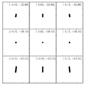
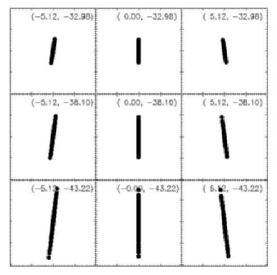
Fig. 2 shows the imaging performance of a classical F/8 Offner based on a 6-inch (152.4 mm) focal length spherical primary (PN K32-836, Edmund Scientific) and a 76.2 mm separation between the image and object. Clearly the performance is very good, with a central field point geometric size of 5 m rms. The worst field point is the bottom right corner of the focal plane (-5.12 mm, -43.22 mm) with 8 m rms spot size.
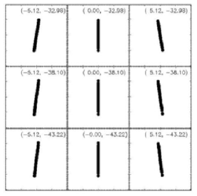
Our method for fabricating the secondary mirror is to select a commercial plano-convex BK7 lens and aluminize its curved surface. Choosing from a catalog makes it likely that exact achievement of is not possible. Selecting with a slightly larger radius of curvature is advantageous. Increasing the radius of , while keeping it concentric with introduces enough third-order astigmatism to cancel fifth-order astigmatism at any given field point. This cancellation, which occurs with a mm, is shown in Fig. 3. The closest readily available match plano-convex lens ( mm; PN K45-284, Edmund Scientific) has slight excess third-order astigmatism, but perfectly adequate and uniform performance of 5 m rms spots (Fig. 4) over the entire field.
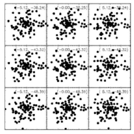
The alignment of the Offner relay presents no serious challenges despite being an off-axis configuration. The performance is robust against decenter of the secondary, which can be displaced by up to 4 mm before the geometric spot size exceeds one 40 m pixel. Secondary tilt is more critical; an error of 1 degree in tilt of about its vertex swells the size to an rms of 11 m and the spots fill one pixel (Fig. 5). However, a secondary tilt of this amplitude also introduces 5.2 mm of image motion. Optical alignment, for example, can be achieved using a reflective reticle placed at point in Fig. 1 and an alignment telescope which views point . In practice, two alignment jigs were constructed which fit over the ends of the snouts on the optical baffle can (see Fig. 6). Each jig has a small central hole which coincides with the focal plane. One jig is illuminated while its image is inspected at the other jig with a jeweller’s loupe. The tip and tilt of the primary mirror are then adjusted using three alignment screws in the base of the mirror cell until the two jigs appear coincident.
2.2 Mechanical design
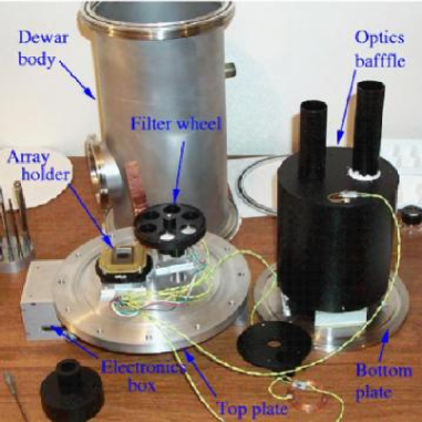
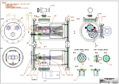
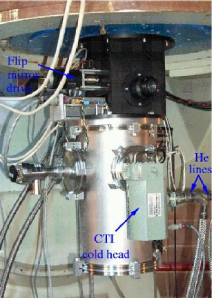
An overview of the layout of the Dewar is shown in Fig. 8 and an picture of the camera on the telescope is shown in Fig. 9. The Dewar body is a semi-custom 8-inch diameter 15-inch long cylindrical 304 stainless steel vacuum vessel (MDC Vacuum Products Corp., Hayward, CA) with two 4-inch ports. Both ends of the cylinder and the two 4-inch ports are fitted with ISO LF flange fittings. The top plate accommodates the quartz Dewar window and two hermetic MIL connectors (Deteronics, South El Monte, CA); one for array control and read-out and one for the stepper motor and temperature sensors. The chip carrier and stepper motor/filter wheel assembly are anchored to the top-end plate by G-10 fiberglass tabs (Fig 6). G-10 provides an extremely stiff and low thermal conductivity (0.53 W m-1 K-1) support. The bottom plate provides the support for the primary mirror of the Offner relay (). Mechanical rigidity for the primary mirror cell is provided by four fiberglass tabs (Fig. 7). A cylindrical optical baffle can (Fig 6) doubles as an radiation shield with input and output snouts that mate with corresponding tubes on the filter wheel assembly and the focal plane array housing (see Fig. 8). The surfaces of the optical baffle can and other components adjacent to the optical beam, such as the filter wheel and array housing, are anodized black to suppress internal reflections. The outer surface of the optical baffle can is wrapped with a single layer of aluminized mylar to enhance its performance as a radiation shield. The optical baffle can attaches to the base of the mirror cell, and thereby provides the alignment and mechanical support for the secondary mirror. One of the two 4-inch flanges is used as an access port for the model 21 CTI He refrigerator, while the other carries a vacuum valve and pumping manifold. During final assembly this port also provides access to the interior of the camera.
2.2.1 Cryogenic filter wheel
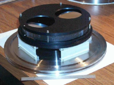
The camera is equipped with a cold filter wheel that can hold up to six one-inch filters. The moment of inertia of the filter wheel is low and the required precision is undemanding so the filter wheel is driven directly by a stepper motor with no gear reduction.
Cryogenic mechanisms are frequently the most unreliable part of infrared instruments. These mechanisms are usually actuated by a warm external motor via ferro-fluidic feed-throughs. A cryogenic motor simplifies design and assembly of the Dewar by eliminating the feed-through. Commercial vacuum-cryogenic stepper motors are available, but they are more than an order of magnitude more expensive than conventional motors.
We have followed the approach developed for the GEMINI twin-channel IR camera at Lick Observatory which uses regular stepper motors with specially prepared dry-lubricated bearings (McLean et al. 1994). The selected motor (PN Vexta PX244-03AA, Oriental Motor, Torrance, CA) is two-phase, 1.8 degree per step, and rated 12VDC at 0.4A. However, we have found that disassembly and degreasing of the motor bearings in isopropyl alcohol, omitting the time consuming step of burnishing with MoS2, is satisfactory. The motor home position is defined optically using an LED and photodiode.
2.2.2 Cryogenic design
A typical -band sky brightness of 14 mag per sq arc second yields about 6000 photons per second per 40 m pixel on the 30-inch telescope. Since we would like to retain the option of using narrow-band (1%) filters for imaging emission lines such as H2 1-0S(1) or Br, our goal is to ensure that the thermal emission from the Offner relay optics and the detector dark current is kept well below this level. Thus, if feasible we would like to reduce any non-astronomical signal to photons s-1 pix-1. Cooling the Offner optics by 70 K from 290 K is sufficient to reduce the m thermal emission by three orders of magnitude, so that the background level is reduced to a few hundred photons per second per pixel. Reducing the dark current to 100 e- s-1 requires cooling the detector below 100 K.
The radiation load from the 290 K inner walls of the vacuum vessel amounts to 5 W (for clean stainless steel walls with an emissivity of 0.05). Multistage thermoelectric coolers can maintain temperature differences between hot and cold sides of as much as K, but their efficiency is typically . Although thermoelectric coolers are practical for CCD cameras which operate at smaller temperature differences, they are not suitable for this application. Liquid nitrogen is readily available; its 77 K boiling point and large latent heat of vaporization (161 J ml-1) render it an almost ideal solution. A cryogen vessel containing, say, 5 liters would be a practical volume, given our design. However, this would require filling once every two days. Installation of a low-emissivity floating radiation shield could increase this interval by a factor of two. Even with this extended lifetime the use of liquid cryogen is incompatible with our objective of operating the infrared camera remotely from Berkeley. Our dilemma was solved when a Model 21 closed cycle helium refrigerator (CTI Corp.) was salvaged from the Berkeley Radio Astronomy Lab’s 85-ft telescope. These cold heads are used extensively by the semiconductor fabrication industry in cryopumps and are readily available as second hand or refurbished items. The high pressure He gas for the CTI cold head is supplied by a compressor manufactured by Austin Scientific, Austin, TX. We use only the 77 K station for cooling; the 20 K station has a vessel containing activated charcoal embedded in epoxy for cryopumping.
On cool down from room temperature the PICNIC array reaches its initial operating temperature of 100 K after about three hours. At this temperature most of the functions of the camera can be checked out. After 12 hours the temperature of the optics and detector are sufficiently stable for reliable operation. In this state the 77 K stage of the Model 21 cold head is at 66 K, the focal plane array is at 82 K, the optics are at 155 K, and the filter wheel is at 187 K. Over the course of a night the temperature stability of the array is 80 mK rms. The Dewar temperatures, including the focal plane array, show slow diurnal variations with an amplitude of 1-2 K which are driven by variations in the ambient temperature. These fluctuations will cause significant dark current variations from night to night. To guard against this the detector block is equipped with a heater resistor that can be used in a temperature control loop. To date, nightly dark frames have proven adequate and the temperature control servo has not be exercised. The closed-cycle refrigerator has one additional advantage related to the fact that the refrigerator can run unattended for many weeks; the delicate detector and optical have suffered fewer thermal cycles, and consequently less thermally induced stress due to CTE mis-matches, than in a conventional liquid cryogen system.
2.3 Array control and readout
The PICNIC array is read out by clocking its multiplexer so that each pixel is sequentially connected to one of the four output amplifiers. When the pixel is accessed the charge is measured but not removed—a reset line must be clocked to reset the pixel and clear the accumulated charge. Consequently, the charge can be read multiple times to eliminate noise and improve the precision of the measurement. Since the camera does not have a mechanical shutter, timed exposures are made by resetting the chip, waiting for the desired exposure time, then reading the chip again. When no exposure is underway the chip is constantly clocked with a reset waveform to flush out the accumulation of charge.
The camera is controlled by commercially available cards that are installed in a Intel/Pentium-based computer running Linux 2.0.34 which is mounted on the side of the telescope about 1 meter from the camera. This machine communicates to the outside world strictly through ethernet. A level shifter and interconnect box is mounted on the vacuum Dewar (Fig. 10).

The PICNIC array requires six CMOS-level clocks and two 5 V power supplies (one analog and one digital). Each quadrant has two shift registers for addressing pixels in the array—one horizontal register and one vertical register. Each register requires two clocks. To obtain a raster scan output, the horizontal register is clocked in the fast direction and the vertical register is clocked in the slow direction. PIXEL and LSYNC are the two required clocks for the horizontal register. The PIXEL input clock is a dual edge triggered clock that will increment the selected column on both edges (odd columns selected on positive edges and even columns selected on negative edges). The LSYNC clock is an active low input clock which will set a “0” in the first latch and a “1” in the remaining latches of the shift register, thereby initializing the shift register to select the first column in the quadrant. Since this is asynchronous to the PIXEL clock, LSYNC should be pulsed low prior to initiation of the first PIXEL clock edge. The horizontal register selects which column bus will be connected to the output amplifier.
These clock sequences are generated by an arbitrary waveform generator card (PN PCIP-AWFG, Keithley Instruments). This card clocks out an 8-bit wide TTL-compatible word with a maximum pattern length of 32K. These words are converted to the 0-5 V levels suitable for driving the PICNIC readout multiplexer and reset lines by a high speed CMOS buffer/line driver (74HCT244). The four detector outputs (one for each 128 128 quadrant) pass through warm monolithic JFET-input operational amplifiers (PN LF356, National Semiconductor) with a gain of 5.1 and a manually adjustable offset, a monolithic sample and hold circuit (PN LF398, National Semiconductor) to a 16 bit analog-to-digital converter card (PN DAS1602/16, Computerboards). The electronics interface box is shown in Fig. 10. This ADC has a 10 s conversion time so the entire chip can be read in 660 ms. The data from this card pass through a very large FIFO (Mega Fifo, Computerboards) so that the data do not have to be read in real time.
The array controller supports several array operations: 1) read—reads chip with no reset; 2) reset—resets the chip but does not read; 3) frame—reset, expose, read; 4) correlated double sampling—resets and read, expose, read; 5) Fowler sampling—resets, read, expose, read. Here expose means wait the requested duration. When a sequence involves two reads the difference of the second minus first read is returned. This usually leads to a positive value of the signal.
2.3.1 Array clocking sequence generation
Generating the clock waveforms for the PICNIC array is central to the entire operation. The key problem is generating the sequence of bytes that is to be down-loaded into the AWFG card. The six PICNIC clocks as well as the analog to digital converter trigger clock have been assigned to the two 4-bit outputs of the AWFG. The AWFG is capable of storing a waveform of up to 32K steps long. When executing a waveform you must specify:
-
•
length of waveform;
-
•
number of times to execute the waveform;
-
•
clock divider specifying number of microseconds per step.
Unfortunately, the maximum waveform length of 32K is not large enough to readout the entire PICNIC array. Instead, we must specify a series of waveforms and execute them sequentially. The AWFG board does allow a new sequence to be loaded as the last sequence is finishing, if the length of the sequence is the same and the clock divider does not change. We have chosen a waveform of length of 4128 clock steps.
The basic step time is created from a 5 MHz clock divided by 25, yielding a 5 s base step time. The full readout sequence is created by stringing together multiple waveforms. Various read modes are supported. For example, the read sequence which just reads through the entire chip and digitizes the result is the combination of two waveforms. The frame sequence is more complex and is composed of three parts: 1) the chip is reset; 2) a variable length wait time (the exposure); 3) The read sequence. The correlated double sampling sequence (CDS) is similar, except that the software subtracts the first values that are read just after the reset from the second reads after the exposure is done and reports the difference.
The software to control the camera was written in C++ for a client-server architecture. Linux device drivers for the three PC cards were written in house. The camera server communicates via TCP/IP sockets and has commands to
-
•
read camera temperatures and status;
-
•
set readout waveforms;
-
•
read the PICNIC array.
The client program which is usually run on a remote machine (e.g., on a workstation in the Berkeley undergraduate lab) reads the array and current telescope information and creates a FITS file with data and detailed header. Since the observatory operations are automated, scripts can be written to combine image acquisition and telescope motions. This is vital in infrared observations where images are often built up from multiple jogged exposures.
The minimum readout time of 660 ms is determined by the speed of the analog to digital converter card. Newer cards with 1 s conversion time are now available that would speed up the read out time by a factor of ten with little change in the software.
3 Performance
The camera operated successfully during the Fall 2000 semester and sufficient observing time has been accumulated by a class of 15 students to demonstrate satisfactory performance. The design has proven reliable. For example, the Linux-based control software has never crashed. The only significant problem was caused by the commercial helium compressor. During early operation the model 21 CTI refrigerator delivered only marginal cooling capacity, with the PICNIC array reaching only 100 K. Intially, we suspected that the cold head was defective since it was a salvaged unit. However, the helium compressor failed catastrophically after only a few thousand hours of operation; when it was replaced with a new unit the expected cryogenic performance was achieved.
The adoption of a specially prepared motor for cryogenic operation was a risk which allowed us to eliminate vacuum feedthroughs. The stepper motor has worked flawlessly, and this elegant solution for Dewar mechanisms has paid off. When the motor is driven continuously, or holding current is applied, sufficient heat is deposited within the Dewar so that after several hours of operation the temperature of the optics and the detector rises by 10–15 K. In normal operation, where the filter wheel is active for a few seconds and then turned off, this heat source is insignificant. Application of holding current is unnecessary because the magnetic forces due to the permanent poles in the motor are sufficient to keep the filter-wheel from moving.
Inspection of images delivered by the Offner relay at room temperature leads us to suspect that it is essentially perfect, but it has not proven possible to quantify the optical performance because the image blur has been dominated by seeing and telescope aberrations. These aberrations are due to telescope collimation errors which are apparent in direct CCD images. The best image sizes delivered by the camera have size of less than 2 pixels FWHM (2.6 arcseconds). However, this is only achieved after careful focusing of the telescope secondary mirror.

In the next three subsections we describe several characteristics of the infrared array and the camera. Exploration and quantification of the camera performance forms the basis of the first lab performed by students. Once they have understood the operation of the camera and mastered the calibration of images they are ready to make astronomical observations such as the one outlined in §3.4.
3.1 Array uniformity
Under high-background conditions flat field accuracy is most important systematic error which limits sensitivity of an array detector to faint sources. Modern arrays deliver very uniform pixel-to-pixel response which means that students can easily construct a flat field that is adequate for all practical purposes. Even this array, which is nominally designated an engineering grade device, has excellent cosmetic characteristics (see Figs. 11 & 12). This is illustrated qualitatively by Fig. 11 which shows a grey-scale image of a -band flat field. This flat is a weighted mean of 11 dark-subtracted twilight sky images. Taking twilight sky images requires careful timing; if they are taken too early the detector saturates, taken too late then there is insufficient signal to form a high signal-to-noise flat. For our pixel etendue ( cm2 str) the optimum time for taking -band images is between sunset or sunrise and 6-degree twilight. A field at high galactic latitude is suitable to avoid stars. The telescope is jogged between each exposure so that stars occupy different pixels in subsequent pictures. Any pixels containing obvious stars are given zero weight and the frames are combined into a weighted mean where outlying pixels (faint stars or cosmic rays) are rejected if their deviation from the mean exceeds three sigma. In a flat normalized so that the median pixel value is 1.0 the best fit Gaussian has an rms of 0.04 (Fig. 12). Three percent of the pixels fall in a tail with low response outside of this distribution, and the array can be considered 97% operable.

3.2 System noise
Under the assumption that the variance in the camera signal is the sum of a constant read noise and Poisson fluctuations it is straightforward to measure the read noise and gain. The data required for this measurement are a sequence of exposures of increasing integration time while the camera views a source of spatially uniform illumination. A pair of exposures is acquired at each integration time. The mean signal level was measured by subtracting a bias frame and the variance computed by differencing the two frames—since the uniformity of flat field is very high the frames were not flat fielded. A straight-line, least squares fit to the linear mean-variance relation yields the readout noise as the intercept and the gain as the slope. The results of this analysis yield 30 e- per data number (DN), and a read noise of 70 e- rms. The majority of this is detector noise, since if one grounds the input to the data acquisition system the variation is on the order of 30 e- rms. A science grade PICNIC array is expected to have a read noise of about 10 e- rms. Despite this elevated detector noise, the data are background limited in all but the shortest exposures. The array saturates at 22,000 DN (660,000 e-) and shows 1% nonlinearity at up to 80% of this level.
| Band | |
|---|---|
| 18.0 | |
| 18.2 | |
| 17.5 |
3.3 Throughput
The efficiency of the camera is expected to be high. The detector quantum efficiency is 60-70% over most of the operating wavelength range. The average filter transmissions are 86% (), 83% (), and 92% () between the half-power points. The protected Al coating for the primary, , has an infrared reflectivity of 97%, and the reflectivity of bare Al on the secondary, , is probably similar. The quartz Dewar window has a transmission of 94%, giving a predicted camera efficiency of 50%. The system efficiency, including the telescope and atmosphere, determined from observation of standard stars is 30% (), 39% (), and 44% (). The camera zero points in magnitudes on a Vega based scale, defined as
are listed in Table 1, where DN s-1 is the count rate in for a star of magnitude .
3.4 An example observation
The region NGC 2024 (Orion B, W12) is a well-studied site of massive star formation located at a distance of about 415 pc (Anthony-Twarog 1982). It is also known as the Flame Nebula, because of the shadow of prominent lanes of extinction formed against a background of H emission from ionized gas. The ionizing stars for this nebula are hidden behind this dust lane. Near-infrared radiation from these stars penetrates the dust and a dense stellar cluster is revealed in the optically-dark region separating the two halves of the nebula. Observations of NGC 2024 provide a dramatic demonstration of the ability of near-infrared radiation to penetrate dust.

NGC 2024 was observed on 2000 Nov 4. Eight 10 s exposures were taken in , , and . The telescope was rastered in a (leaving out the central location) with offsets of 36 arc seconds in RA and DEC between each pointing. Exposures were collected in , , and for the target and then the telescope was offset to blank sky 6 arc minutes to the east and the filter sequence was repeated.

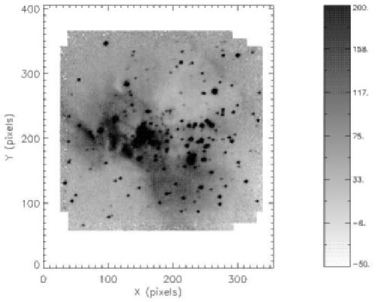

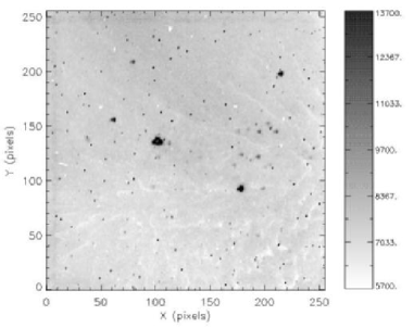
Fig. 13 shows an individual band image. Only the brightest stars ( mag) can be seen in raw images. A sky-subtracted and flat-fielded image (Fig. 14) shows significantly more detail, including the nebulosity. The exposure mask for this observation is shown in Fig. 15, and the final mosaic composed using using a weighted sum of the registered images is shown in Fig. 16. The , , and images have been registered and combined into a three color composite. The optically invisible, highly reddened, stellar cluster behind the central dark lane stands out clearly (Fig. 17).
4 Conclusions
We have designed and built a high performance near-infared array camera for the 30-inch telescope at Leuschner Observatory. Our design eliminates custom parts in favor of commercial components. The array control and readout electronics are composed entirely of standard PC cards. The only custom board is the interface which buffers the clocks from the waveform generator and amplifies the analog signal from the detector outputs. The Offner-based optics relay the telescope image at unit magnification via a cold stop which provides effective control of thermal radiation from the telescope and its environment. The camera has been used successfully in an undergraduate laboratory class in Fall 2000.
References
- Anthony-Twarog (1982) Anthony-Twarog, B. J. 1982, AJ, 87, 1213
- McLean et al. (1994) McLean, I. S. et al. 1994, Proc. SPIE, 2198, 457
- Murphy et al. (1995) Murphy, D. C., Persson, S. E., Pahre, M. A., Sivaramakrishnan, A. & Djorgovski, S. G. 1995, PASP, 107, 1234
- Nelson, McLean, Henriquez & Magnone (1997) Nelson, B., McLean, I. S., Henriquez, F. & Magnone, N. 1997, PASP, 109, 600
- Offner (1975) Offner, A. 1975, Opt. Eng., 14, 130
- Parthasarathy et al. (1998) Parthasarathy, R., Frank, C., Treffers, R., Cudaback, D., Heiles, C., Hancox, C., Millan, R. 1998 Am. J. Phys., 66, 768
- Treffers, Richmond & Filippenko (1992) Treffers, R. R., Richmond, M. W. & Filippenko, A. V. 1992, ASP Conf. Ser. 34: Robotic Telescopes in the 1990s, 115
- Vural et al. (1999) Vural, K. et al. 1999, Proc. SPIE, 3698, 24