The SPIFFI image slicer: Revival of image slicing with plane mirrors
Abstract
SPIFFI (SPectrometer for Infrared Faint Field Imaging) is the integral field spectrograph of the VLT-instrument SINFONI (SINgle Far Object Near-infrared Investigation). SINFONI is the combination of SPIFFI with the ESO adaptive optics system MACAO (Multiple Application Concept for Adaptive Optics) offering for the first time adaptive optics assisted near infrared integral field spectroscopy at an -telescope. SPIFFI works in the wavelength ranger from to with a spectral resolving power ranging from to . Pixel scale ranges from to seconds of arc. The SPIFFI field-of-view consists of pixels which are rearranged with an image slicer to a form a long slit.
Based on the 3D slicer concept with plane mirrors, an enhanced image slicer was developed. The SPIFFI image slicer consists of two sets of mirrors, called the small and the large slicer. The small slicer cuts a square field of view into 32 slitlets, each of which is 32 pixels long. The large slicer rearranges the 32 slitlets into a 1024 pixels long slit. The modifications to the 3D slicer concept affect the angles of the plane mirrors of small and large slicer and lead to an improved slit geometry with very little light losses. At a mirror width of the light loss is . All reflective surfaces are flat and can be manufactured with a high surface quality. This is especially important for the adaptive optics mode of SINFONI. We explain the concept of the SPIFFI mirror slicer and describe details of the manufacturing process.
Keywords: image slicer, infrared, integral field, spectrograph, VLT
1 INTRODUCTION
Classical imaging spectroscopy uses scanning techniques to obtain both spatial and spectral information of a two-dimensional field-of-view on the sky. Either wavelength-scanning with a Fabry-Perot camera or slit-scanning with a long-slit spectrograph are used to generate a data cube. Fabry-Perot imaging covers a large field-of-view with a limited wavelength range while long-slit spectroscopy yields a spectrum over a wide wavelength range and a limited field-of-view. Depending on the object of interest and scientific proposal either scanning technique might be well suited. However, if compact objects are observed, only a fraction of the data taken by scanning techniques contains useful information because most of the large field-of-view or long slit length covers sky.
For compact objects the technique of integral field spectroscopy is better suited. With an integral field spectrograph the spectra of all pixels in a two-dimensional field can be obtained simultaneously therefore reducing the integration time over scanning techniques. But this multiplex advantage is not the only advantage of integral field spectroscopy. Especially in the near-infrared wavelength range the variability of the atmosphere makes it difficult to generate a data cube from data which were taken in a time sequence. All spectra taken with an integral field spectrograph are affected equally by the atmosphere resulting in a much improved data quality.
Presently three major techniques are used for integral field units.
-
•
The TIGER-concept [1] uses a microlens array to dissect the field-of-view into individual pixels. The microlens array has a very high filling factor of almost . Each microlens creates an image of the telescope pupil. Because of their small size they are called micro-pupils. All micro-pupils form an array and because of their small size the filling factor of the micro-pupil array is very small. The idea of the TIGER concept is to image the micro-pupil array onto the array detector but disperse the light of each micro-pupil onto the unfilled portions of the detector. This concept has been successfully used in the visible wavelength range.
-
•
Another technique uses a fiber bundle to transform a two-dimensional field into a slit which is fed into a long-slit spectrograph. To transform the field-of-view the fiber bundle has a two-dimensional cross-section on one end and a one-dimensional cross-section on the other end. To increase the coupling efficiency often a microlens array is used at the entrance end. Examples for instruments using this technique are INTEGRAL [2] in the visible wavelength range, and SMIRFS-II [3] and COHSI [4] in the near infrared wavelength range. Also the first design of SPIFFI followed this approach [5].
-
•
The third concept uses a mirror slicer which dissects the field-of-view into slitlets and rearranges these slitlets to form a slit which is fed into a long-slit spectrograph. This concept was first used in the integral field spectrograph 3D [6] which was designed and built at the Max-Planck-Institut für extraterrestrische Physik (MPE). The new near-infrared integral field spectrograph SPIFFI [7] of MPE uses this concept which is described in this article.
Integral field spectroscopy became an interesting and useful technique only with the advent of large size array detectors. Only large array detectors permit to do integral field spectroscopy with large wavelength range in a sufficiently large field-of-view.
3D for example uses a NICMOS 3 detector [8] with pixels of which rows correspond to the spectra of 256 spatial pixels in a pixels large field-of-view. With the new Rockwell HAWAII detector [9] with pixels a four times bigger field-of-view can be covered and either the spectral wavelength range or the spectral resolving power can be quadruplicated. To make use of these new detectors at MPE the new instrument SPIFFI using a HAWAII array was designed and is currently under construction. Its scientific applications range from investigations of our solar systems to observations of cosmologically distant galaxies [10]. In this article we describe the design and fabrication of the SPIFFI image slicer, the “heart” of SPIFFI.
2 3D IMAGE SLICER
3D, designed and built by MPE, is the first near-infrared integral field spectrograph which utilizes a new concept for the image slicer. The 3D image slicer uses a system of plane mirrors to transform a two-dimensional field-of-view into a pseudo-slit. A NICMOS 3 detector is used in such a way that spectra of 256 pixels in a pixels large field-of-view can be obtained simultaneously.
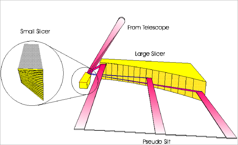
The 3D image slicer consists of two sets of mirrors. The first set of mirrors, the small slicer, is a stack of 16 mirrors placed in the focal plane of the telescope. Th mirrors are only wide and each mirror is tilted by a different angle but all the same direction (see Figure 1). The 16 different tilt-angles lead to a sliced field-of-view consisting of 16 stripes fanned out over . The projected length of the 16 stripes in the telescope focal plane is , corresponding to pixels of width.
After the small slicer the fan of 16 stripes hits the second set of mirrors, called the large slicer. The large slicer reflects the rays from to form a pseudo-slit. The tilt-angles of the 16 mirrors of the small and large slicer are such that the position of the telescope pupil is conserved. To achieve this the centers of the large slicer mirrors also have lie on a hyperbola. The large slicer mirrors are placed at a distance from the small slicer where the 16 stripes don’t overlap anymore, resulting in a contiguous pseudo-slit of 16 slitlets arranged in a staircase pattern (see Figure 1). The total length of the pseudo-slit is .
Neither the small slicer mirrors nor the large slicer mirrors are located entirely in the telescope focal plane. Defocusing at the small slicer and especially at the large slicer leads to a not perfect slicing efficiency of the 3D image slicer. At the small slicer, due to the tilt-angle, the defocus spot outside the mirror center is larger than the mirror width of . At the large slicer, due to the distance between the small and large slicer, the defocus spot extends over the mirror length of . Both effects lead to light losses through the image slicer. The slicing efficiency depends on the tilt-angle of the small slicer mirrors and the distance between the small and large slicer. Because a smaller tilt-angle at the small slicer leads to an increase of the distance between the small and large slicer an optimal combination of tilt-angle and distance exists. The 3D slicer, which is designed to give pixels at -class telescopes has an efficiency of .
3 SPIFFI IMAGE SLICER
For the SPIFFI instrument a Rockwell HAWAII detector with detector elements is used. With this detector size an image slicer with pixels can be realized. Because the 3D slicer cannot be used for this format a new image slicer has to be built for SPIFFI. Also, the SPIFFI instrument is designed to be used on an -telescope which puts additional constraints on the image slicer. A simple scaling of the 3D slicer to 1024 spatial pixels would result in a long slicer with an efficiency of . Both the size and the efficiency are not acceptable for SPIFFI.
3.1 Modified 3D Slicer
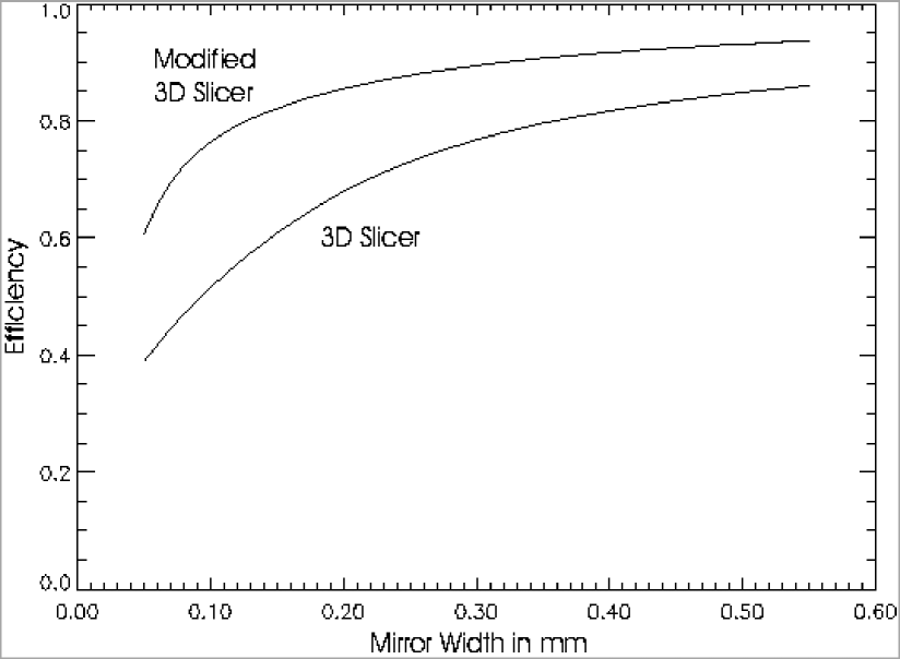
The only way to reduce the size of the SPIFFI image slicer is to decrease the pixel size, i.e. the mirror width of the small slicer mirrors. However, decreasing the mirror width causes the efficiency of the slicer to decrease. Two effects are adding to yield a rapid decrease in slicer efficiency (see Figure 2). The fraction of the defocus spot area of a pixel area increases with decreasing mirror width. In addition if the pixel size on the sky has to stay constant, the beam in the telescope focal plane has a larger f-ratio, increasing the defocus spot diameter even more. Another limitation is the feasibility of mirrors with a width . For the SPIFFI image slicer a pixel size of is chosen, resulting in a pseudo-slit length of . This is a compromise between a still feasible mirror width and the overall size of the slicer.
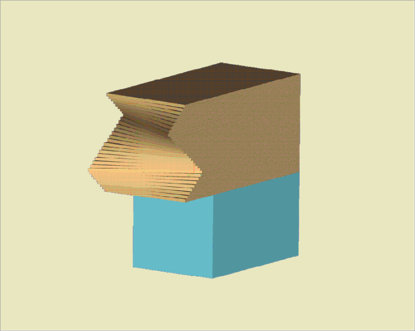
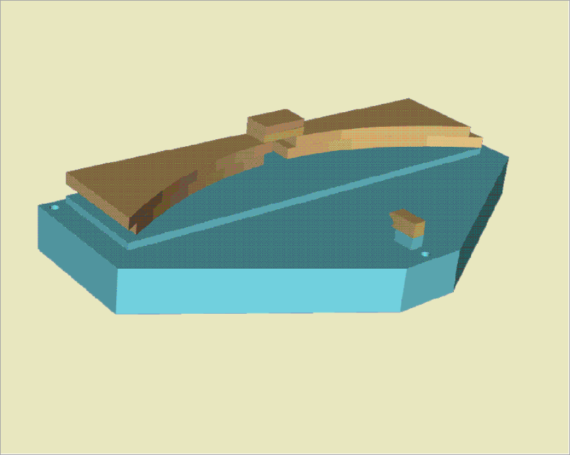
However, as can be seen from Figure 2 the efficiency of a 3D-type slicer with pixels and mirror width is only . To improve the slicer efficiency three major changes to the 3D slicer concept have been applied (see also Figures 3 and 4):
-
1.
symmetric slicer layout,
-
2.
additional mirror tip-angle orthogonal to the tilt-angle of the 3D slicer,
-
3.
maximum tilt-angle of at small slicer.
The 3D-slicer has an asymmetric layout (see Figure 1). If this layout was used in the SPIFFI slicer, the maximal distance between small and large slicer would equal the pseudo-slit length of . The symmetric layout reduces the maximum distance between the small slicer and the large slicer by a factor of 2 to only half the pseudo-slit length, thus reducing the maximal defocus spot diameter by a factor of 2.
Because the 3D-slicer uses only one tilt-angle the pseudo-slit has a staircase-pattern where the corners of adjacent slitlets touch each other (see also Figure 1). Also the mirror facets of the large slicer intersect at this position. Because these facets are out of focus a fraction of the light from pixels at the end of each slitlet is reflected by the wrong facet and is lost. With an additional tip-angle of the slicer mirrors orthogonal to the tilt-angle it is possible to change the staircase pattern of the pseudo-slit in 3D to an almost arbitrary slit pattern. For SPIFFI we chose a two-layer brick-wall pattern. With this pattern the individual slitlets of the pseudo slit don’t touch each other anymore, and the large slicer mirrors can be oversized to reflect the entire defocused slitlet.
The modification explained in the above paragraph is only possible up to a maximum distance between the small and large slicer. If the distance was to large the defocus spot diameter would be larger than the maximal possible mirror size of the large slicer. With a two-layer brick-wall pattern the minimal tilt-angle has to be and the distance between the small and large slicer would be . Because this would be too large to fit into the SPIFFI optical train a maximum tilt-angle of was chosen.
The modifications to the 3D slicer concept lead to a very high efficiency of the SPIFFI image slicer. At a maximum tilt-angle of the losses at the small slicer are reduced without increasing the losses at the large slicer. With a mirror width of all the light coming from the small slicer is reflected by the large slicer. In Figure 2 we show the light losses for an image slicer according to the 3D-slicer concept and according to the modified 3D-slicer concept. Assumed is a field-of-view with pixels with an input beam f-ration of f/30, corresponding to a pixel size of seconds of arc at an -telescope. Even for a mirror width of the light losses of the SPIFFI image slicer are only .
Another advantage of the symmetric slicer layout is that instead of 32 different slicer mirrors for the small and large slicer only 16 different slicer mirrors, but two of each, have to be made. This reduces the cost of the SPIFFI image slicer. However, with a symmetric layout the direct view from the telescope along the optical axis onto the small slicer is blocked by the central mirrors of the large slicer. Therefore, the two central mirrors of the big slicer are moved and placed on top of the top-layer of the large slicer leaving a hole for the view onto the small slicer along the optical axis. Because these two slitlets have larger tip-angles the shadowing losses at the small slicer are also larger. However, in the two-dimensional field-of-view these slitlets correspond to the top and bottom slitlets. The correlation between the small and large slicer mirrors is such that slicer-efficiency is largest in the field-center of SPIFFI and is less at the field-edges.
To reduce thermal background radiation the image slicer is cooled down , the working temperature of SPIFFI instrument. Based on experience with 3D this increases the sensitivity of SPIFFI especially in the wavelength range above .
3.2 Fabrication
The entire SPIFFI image slicer, including the base plate, is made from Zerodur. Because of its low linear thermal expansion coefficient the slicer design needs not be corrected for the slicer working temperature of .
The small as well as the large slicer consist of individual mirrors which are manufactured using conventional optical polishing techniques. The achieved surface quality is of order which is necessary for the adaptive optics mode of SINFONI.
The good surface quality also allows to optically contact the mirrors to build the mirror stacks. We have performed tests under vacuum and at low temperatures which show that the optically contacted Zerodur surfaces don’t separate. The same technique is used to mount the slicer mirror stacks to the base plate. Hence, the SPIFFI image slicer is a completely monolithic device. It is not subject to thermal stresses originating from differential thermal expansion coefficients as it would be the case if glue was used in the assembly of the individual mirrors.
To achieve a high accuracy on the tip- and tilt-angles a set of master prisms with the correct angles was made. They are large enough to be accurately polished and measured. Using these master prisms all slicer mirrors are fabricated. Angles are polished to better than seconds of arc, length dimensions are known better than .
An accurate assembly of the slicer mirrors to the small and large slicer is achieved by checking for interference fringes between a reference plate and the individual slicer mirrors. This way the high accuracy of the individual slicer mirrors is conserved during the assembly of the small and large slicer. The assembly of the small and large slicer on the base plate is done with the help of a traveling microscope.
After the small and large slicer are assembled the mirror surfaces are coated with gold. To protect the sensitive gold layer the mirrors are coated with a thin layer of fused silica.
3.3 Mounting
The SPIFFI image slicer is mounted in a housing which acts as the holder as well as the light baffle. Special care has to be taken to compensate for the differential thermal expansion coefficient of the Zerodur slicer and the Aluminium holder. No stress shall be applied to the slicer while at the same time keeping its position stable within .
In the design used the SPIFFI image slicer is held only at its base plate. The base plate is held between lapped Invar pads avoiding any point contact between the metal holder and the slicer. The Invar pads touching the base plate are allowed a lateral movement of with respect to the Aluminium holder. This is achieved through a ball bearing between the pads and the Aluminium holder.
The position of the SPIFFI image slicer in the light-path orthogonal to the optical axis is not critical. The optical layout of SPIFFI allows to compensate for offsets in these directions and the machining tolerances are small enough to place the slicer accurately enough. However, to be able to focus the slicer it is necessary to adjust the position of the slicer along the optical axis. This is done with a micrometer screw which allows to defocus the SPIFFI image slicer by .
References
- [1] R. Bacon, G. Adam, A. Baranne, G. Courtes, D. Dubet, J. P. Dubois, E. Emsellem, P. Ferruit, Y. Georgelin, G. Monnet, E. Pecontal, A. Rousset, and F. Say, “3D spectrography at high spatial resolution. I. Concept and realization of the integral field spectrograph TIGER.,” A&AS 113, pp. 347+, 1995.
- [2] S. Arribas, D. Carter, L. Cavaller, C. del Burgo, R. Edwards, F. J. Fuentes, A. A. Garcia, J. M. Herreros, L. R. Jones, E. Mediavilla, M. Pi, D. Pollacco, J. L. Rasilla, P. C. Rees, and N. A. Sosa, “INTEGRAL: a matrix optical fiber system for WYFFOS,” Proc. SPIE 3355, pp. 821–827, 1998.
- [3] R. Haynes, R. Content, J. Turner, J. R. Allington-Smith, and D. Lee, “SMIRFS-II: multiobject and integral-field near-IR spectroscopy at UKIRT,” Proc. SPIE 3354, pp. 419–430, 1998.
- [4] M. A. Kenworthy, I. R. Parry, and K. Taylor, “Integral field units for SPIRAL and COHSI,” Proc. SPIE 3355, pp. 926–931, 1998.
- [5] M. Tecza, N. A. Thatte, A. Krabbe, and L. E. Tacconi-Garman, “SPIFFI: a high-resolution near-infrared imaging spectrometer,” Proc. SPIE 3354, pp. 394–403, 1998.
- [6] L. Weitzel, A. Krabbe, H. Kroker, N. Thatte, L. E. Tacconi-Garman, M. Cameron, and R. Genzel, “3D: The next generation near-infrared imaging spectrometer,” A&AS 119, pp. 531–546, 1996.
- [7] F. Eisenhauer, M. Tecza, S. Mengel, N. Thatte, C. Röhrle, and K. Bickert, “Imaging the Universe in 3D with the VLT: The Next Generation Field Spectrometer SPIFFI,” Proc. SPIE submitted, 2000.
- [8] J. G. Poksheva, L. R. Tocci, M. C. Farris, and S. E. Tallarico, “NICMOS flight hardware 256 X 256 MCT detector array configuration,” Proc. SPIE 1946, pp. 161–169, 1993.
- [9] K. W. Hodapp, J. L. Hora, D. N. B. Hall, L. L. Cowie, M. Metzger, E. Irwin, K. Vural, L. J. Kozlowski, S. A. Cabelli, C. Y. Chen, D. E. Cooper, G. L. Bostrup, R. B. Bailey, and W. E. Kleinhans, “The HAWAII Infrared Detector Arrays: testing and astronomical characterization of prototype and science-grade devices,” New Astronomy 1, pp. 177–196, 1996.
- [10] S. Mengel, F. Eisenhauer, M. Tecza, T. N., C. Röhrle, and K. Bickert, “A new era of spectroscopy: SINFONI, NIR integral field spectroscopy at the diffraction limit of an 8m-telescope,” Proc. SPIE submitted, 2000.