Imaging the Universe in 3D with the VLT: The Next Generation Field Spectrometer SPIFFI
Abstract
We present SPIFFI, the integral field spectrometer for the VLT. This instrument allows simultaneous observation of infrared spectra in more than 1000 image points of a two dimensional field. With its set of four gratings and a pixel scale that can be varied by a factor of ten, SPIFFI provides high flexibility, and at the same time offers the unique possibility of diffraction limited imaging spectroscopy at an 8m-class telescope, when fed by the adaptive optics system MACAO. We outline the scientific drivers for building such an instrument, the concept of image slicing, the optical design, and the implementation of SPIFFI.
Keywords: Infrared, Integral Field, Spectroscopy, Image Slicer, VLT
1 INTRODUCTION
1.1 The need for near infrared integral field spectroscopy
A large number of astronomical problems demand spectroscopy of every image point of a two-dimensional field on the sky, because the objects of interest have a complex spatial structure. These objects span the whole Universe ranging from high redshift galaxies to the moons and planets in our solar system. Merging galaxies in the early Universe need to be spatially resolved to uncover the underlying dynamics. The analysis of giant black holes in the center of active galactic nuclei requires the knowledge of the two dimensional velocity fields to overcome ambiguities from anisotropic motion. The starforming history of extragalactic starbursts can only be derived, if we can resolve the individual clusters. New stars are born in a highly complex environment, exhibiting discs and outflows with different spectral characteristics, which would be veiled in long slit spectra. There are several classic techniques like slit-scanning, Fabry-Perot-interferometry and Fourier-transform-spectroscopy which provide spectra for a two dimensional field, but they all need several exposures for a single field. However, modern integral field spectrometers with lenslet arrays or image slicers can record the spectra for every point of a two dimensional field in a single exposure. Making most efficient use of the telescope, observations with integral field spectrometers are also more easily to correct for variations in the atmospheric transmission. This is specifically important in the near infrared wavelength range, where the atmosphere varies on time scales of minutes. Also adaptive optics observations, which provide images with a spatial resolution close to the diffraction limit of a telescope, suffer much from the time varying correction, and advanced image reconstruction techniques like deconvolution require a simultaneous observation of the two-dimensional field with a field spectrometer.
There are several reasons, both object inherent and technical, to carry out astronomical observations at near infrared wavelengths: First, many of the faint objects we are looking for — like in the Hubble Deep Field — are at high redshift. Therefore a lot of the well established “optical” spectral diagnostics are shifted beyond 1 micron. Second, many of the interesting objects in the universe — like nuclei of galaxies, star and planet forming regions — are hidden behind dust. For example our Galactic Center is dimmed in the visible by about 30 magnitudes, while we suffer from only 3 magnitudes of extinction in K-Band (2.2 m). And third, high angular resolution through the earth’s atmosphere is much easier achieved at longer wavelengths. Even though there is no principle limitation to reach the diffraction limit in the visible, the high complexity of an adaptive optics system for very large telescopes suggests that we start with the easier task of correcting in the near infrared.
1.2 The SPIFFI project
Based on the scientific and technical motivation outlined in the previous section, the Max-Planck-Institut für extraterrestrische Physik (MPE) in Garching, Germany, started in the late 90’s the development of SPIFFI (SPectrometer for Infrared Faint Field Imaging), a state of the art adaptive optics assisted near infrared integral field spectrometer. Because of the great success of SPIFFI’s precursor 3D [1], SPIFFI was thought as a travelling instrument for several telescopes, including the Calar Alto Observatory, the European Southern Observatory (ESO) and the Large Binocular Telescope (LBT). In order to keep SPIFFI’s dimensions and weight to its absolute minimum, we started the development of a new image slicer based on flared fibers [2]. However, given the very good collaboration with ESO on previous instrument projects (SHARP I and SHARP II) [3], MPE decided to build a VLT specific instrument SPIFFI, to be assisted with ESO’s adaptive optics system MACAO. This combination of an adaptive optics system and an integral field spectrometer is jointly refered to as SINFONI [4] (SINgle Faint Object Near Infrared Investigation). From the very beginning, SINFONI was thought to be a fast track instrument. First light is foreseen in 2002 on VLT UT3. Since SPIFFI will remain at the VLT, the constraints on size and weight have been relaxed, and a mirror based image slicer could be considered for SPIFFI again. Given the superior performance of a mirror based image slicer, the tight schedule for SPIFFI, and unexpected delays in the development of the fiber based image slicer, we decided to equip SPIFFI with a mirror slicer [5].
 |
1.3 The SPIFFI instrument
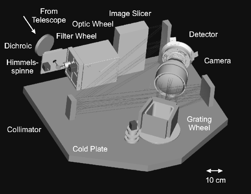
SPIFFI records simultaneously the spectra of all 32 x 32 image points of a two-dimensional field of view. It thus allows spectroscopy of objects with a complex spatial structure, and will make the most efficient use of observing time compared to alternative imaging spectrographs. Given the relevance of near infrared spectroscopy for many areas of modern astronomy, SPIFFI will cover the wavelengths of the three atmospheric bands J (1.1 m - 1.4 m), H (1.45 m - 1.85 m), and K (1.95 m - 2.45 m), i.e. from 1.1 m - 2.45 m. The instrument is fully cryogenic, and will be equipped with an 1k x 1k HAWAII [6] array from Rockwell. The image scale of SPIFFI allows both Nyquist sampled imaging at the diffraction limit of the telescope ( 0.025 arcsec/pixel), and seeing limited observations (0.25 arcsec/pixel). An intermediate image scale provides a compromise of field size and spatial resolution. The spectral resolution of the spectrometer is about 4000 for all three wavelength bands J, H, and K, which allows detailed kinematic study of galaxies, and at the same time an effective OH-avoidance of the atmospheric emission lines in the NIR. A more moderate resolution R 2000 is implemented, too, for objects that are too faint for high resolution spectroscopy, covering H & K simultaneously. The optics is designed for gratings with a resolution of up to 10000, which may be integrated in future upgrades of SPIFFI. Figure 1 shows a perspective view of the main components of SPIFFI.
 |
2 OPTICS
2.1 Overview
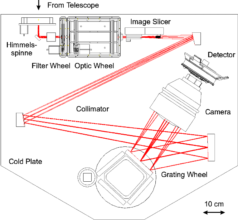
The SPIFFI integral field spectrometer will consist of three basic components: (a) Preoptics: The Preoptics reimage the object plane from the adaptive optics onto the image slicer, providing the different pixel scales. In addition, a cold stop at the intermediate pupil position will allow efficient suppression of the thermal background. The pre optics will also host broad band filters for selecting the wavelength range. (b) Image slicer: The image slicer cuts the two dimensional field into a set of 32 individual slitlets, and rearranges them to a one-dimensional pseudo long slit. This image slicing is done by a set of 64 plane mirrors. (c) Spectrometer: The spectrometer reimages the pseudo long slit from the image slicer onto the detector. The gratings are located at the intermediate pupil position. In addition, a so called ”Himmelsspinne” (sky spider) at the entrance of the instrument will allow the observation of the sky background simultaneous with the astronomical target. Figure 2 shows a schematic view of the SPIFFI optics.
2.2 Imaging optics
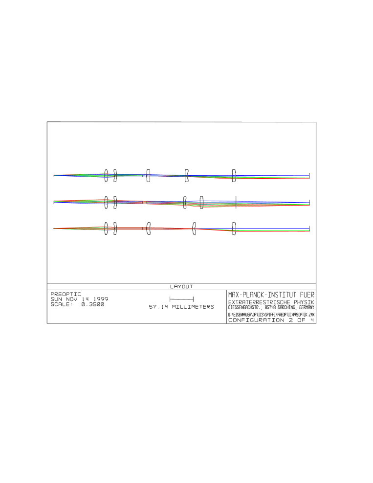
The preoptics reimage the focal plane of the adaptive optics onto the image slicer. It consists of a fixed collimator, a filter wheel, and an optic wheel. The preoptics provide three different magnifications (17.8 x, 4.45 x, 1.78 x) with equivalent pixel scales of 0.025 arcsec/pixel, 0.1 arcsec/pixel, and 0.25 arcsec/pixel. In addition, a pupil imaging lens will allow for an accurate alignment of SPIFFI’s optical axis with the telescope / adaptive optics. Figure 3 shows the preoptics with the three imaging lenses.
 |
The preoptics use only spherical lenses made from barium fluoride and IRG2 from Schott. With a focal length of 85.5 mm, the collimator reimages the entrance pupil on a 6.0 mm diameter cold stop. The preoptics are telecentric. The maximum deviation from the on-axis pupil location is less than 1 % of the corresponding radius across the whole field. The residual distortion is less than 0.025 % for all image scales. All image scales are diffraction limited, and provide a nominal Strehl ratio 97 % for all wavelengths across the whole field. The filter wheel is located in the collimated beam in front of the cold stop.
2.3 Image Slicer
The image slicer [5] transforms the two-dimensional field into a one dimensional slit. This long slit is then dispersed by a classical spectrometer. The first concept of SPIFFI was based on optical fibers [2], where the image plane is sampled by a bundle of these fibers, which are then rearranged to a ”long slit”. While this concept is still promising for future projects [7], the tight schedule for SPIFFI and problems with the manufacturing of this fiber bundle led to the revival of the mirror slicing concept, as used in the MPE 3D spectrometer [1]. The first set of mirrors, called ”Small Slicer”, is located in the object plane, and redirects the light from different field points towards different directions, thus separating the beams from each other. At the location of the second set of mirrors, called ”Large Slicer”, the beams are completely separated. However, the beams point towards different directions, or in other words, the exit pupils of the different rows do not overlap anymore. The large slicer realigns the pupils again, e.g. the beams from the different rows are parallel at the exit of the image slicer, but still spatially separated. Only plane mirrors are used in the image slicer. There are several points to consider for the detailed design of this slicer:
(a) For a total of 32 x 32 pixels, the length of the final pseudo long slit is 1024 times the width of the small slicer mirrors. For example, when using 1 mm wide mirrors, the spectrometer would have to work with a slit 1 m long. In order to keep the instrument size small, one therefore should make the mirrors as small as possible. Choosing too small a mirror size, however, leads to strong defocus effects, limiting the efficiency of the small slicer. The reason for this is that for a given projected pixel size on the sky, smaller mirrors imply a faster beam at the slicer. A faster beam, however, reduces the focal depth, and vignetting at the interface between two mirrors gets more serious. Also it is very hard to manufacture mirrors smaller than a few hundred microns. The compromise for SPIFFI is a width of 300 m for the mirrors of the small slicer, thus providing a pseudo long slit of 307.2 mm.
(b) Since the beams are diverging towards the large slicer, the light from neighboring rows will overlap slightly at the edge of the mirrors from the large slicer, if they are aligned along a single layer. To prevent this, the mirrors of the large slicer are aligned in a brick wall pattern. There is no crosstalk at the position of the large slicer, but the pseudo long slit will consist of two truncated slits.
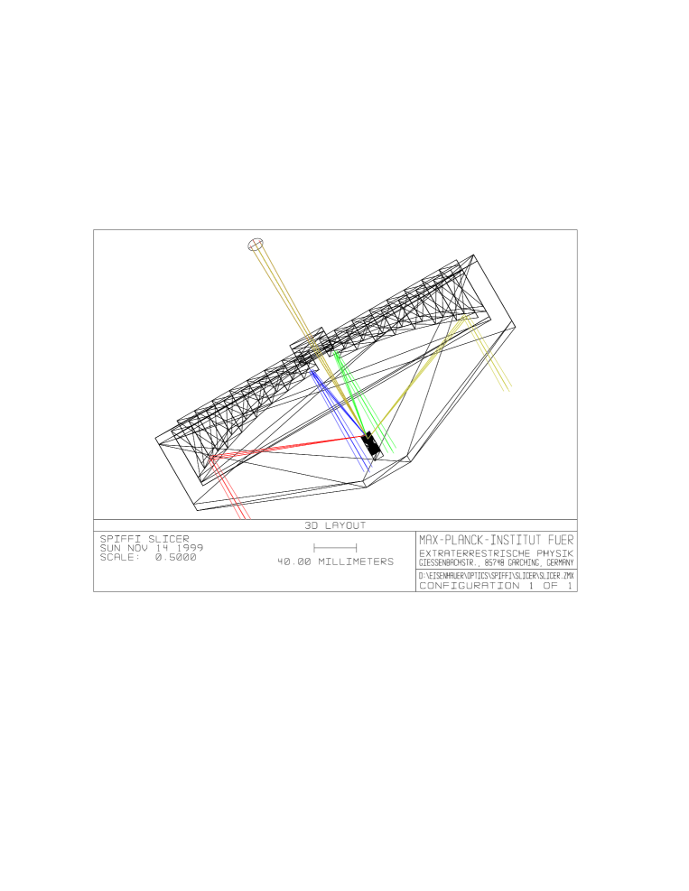
Figure 4 shows the design for the SPIFFI mirror slicer. The whole slicer will be fabricated from Zerodur. All elements will be optically contacted, no glue etc. is used. The monolithic design allows the slicer to be cooled down to the temperature of 77 K. Several cool downs have been carried out with a test slicer without any problems. The mirrors will be coated with a highly reflective gold layer.
 |
2.4 Spectrometer
The spectrometer consists of a collimator, the gratings, and a camera.
The collimator of the SPIFFI spectrometer is a three mirror anastigmat. It consists of one spherical and two off-axis prolate elliptical mirrors (see figure 2). This system combines the advantage of a large one-dimensional field of (slit length: 307.2 mm) with a very compact design, and requires only 3 mirrors. Its nominal focal length is 2886.5 mm. The optics is operated off-axis. The nominal Strehl ratio is 96 % across the whole field, for all wavelengths, and for all pixel scales. The location of the exit pupil for the different field points of the long slit varies by less than 1 % of its radius. The distortion along the slit less than 0.2 %. The mirrors will be diamond turned from nickel plated aluminum. Postpolishing will reduce the residual surface roughness to less than 50 Ångstrøm. The mirrors will be gold coated (with protection layer).
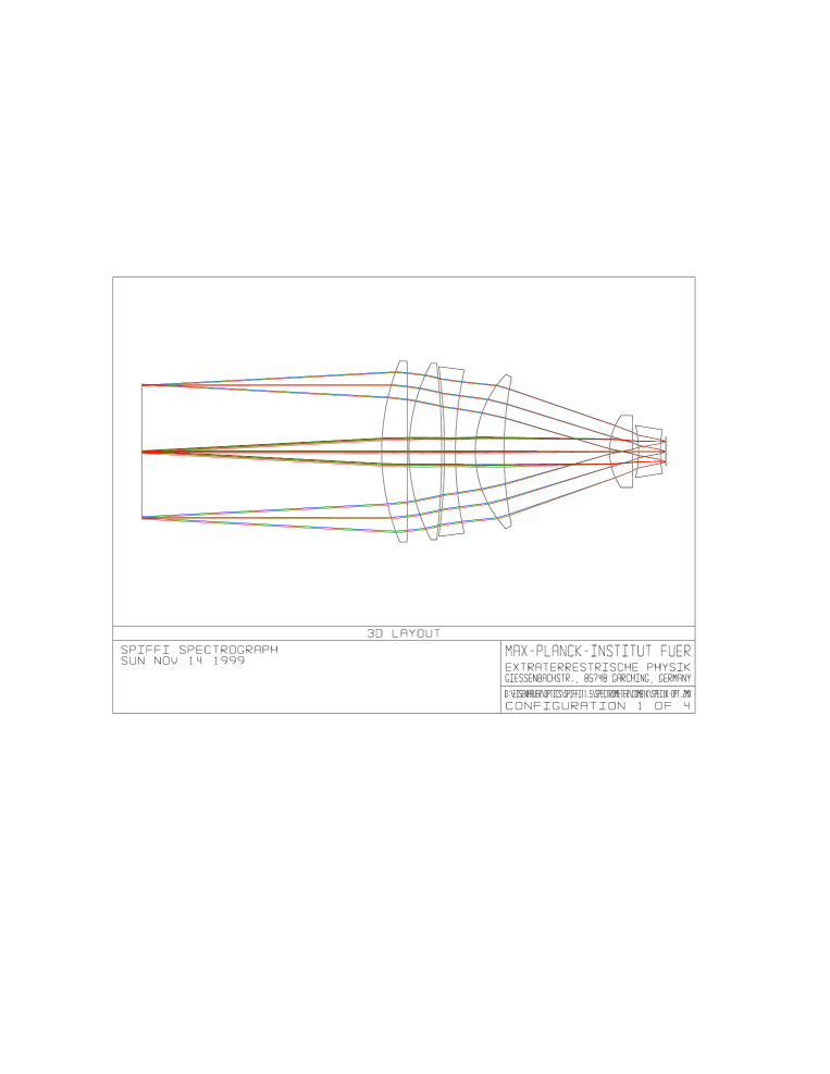 |
The nominal focal length of the camera (figure 5) is 178 mm. Because of the anamorphic magnification from the grating, and because of a small pupil distortion from the collimator, the beam size at the exit of the grating is 125 mm at the 0.25 arcsec/pixel scale. The field of view is . In order to clear the beam, the entrance pupil of the camera was chosen to be 220 mm in front of the first lens surface. The camera was optimized to correct for -0.2652 % of anamorphic distortion from the gratings, so that the spectra of a single image point differ by less than 1/5 of a pixel from a straight line. The camera is completely diffraction limited — i.e. nominal Strehl ratio 100 % — at all wavelengths (1.1 m - 2.45 m) when operated with the adaptive optics image scale of 0.025 arcsec/pixel. The nominal Strehl ratio for the 0.1 arcsec/pixel scale is everywhere 90 %. For operation with the seeing pixel scale with 0.25 arcsec/pixel (biggest beam), the camera was optimized for smallest spot size The nominal RMS spot radius is 5 m everywhere. For comparison, the size of a pixel is 18.5 m.
The heavy constraints on the image quality, and the large f-number of 1.4 of the camera can only be fulfilled with the use of lenses made from the special infrared glass IRG2 from Schott. Since this glass is not available from stock, MPE has ordered a custom melt.
SPIFFI will have four plane gratings, covering the atmospheric J, H, K, and H & K bands. The gratings are operated in Ebert configuration. The size of all gratings is 160 mm x 140 mm. The blanks are made from nickel- and gold plated aluminum and are light weighted. All gratings are directly ruled and are blazed for highest efficiency. The tolerance on surface flatness corresponds to 90 nm RMS in the diffractive wavefront at normal incidence. The average efficiency of all gratings will be around 60 % to 80 %.
2.5 Himmelsspinne
The Himmelsspinne facilitates simultaneous observations of an object and a blank sky field. The observer may choose one of four fields, with separations of about 0.25, 0.5, 0.75 and 1 arc minute from the center of the SPIFFI field of view. Light from the chosen field is redirected via two plane mirrors onto a corner of the image slicer, providing simultaneous measurements of the night sky background level. The number of pixels occupied by the sky fields can be selected by the observer.
3 MECHANICS
3.1 Cryostat
All optics and the detector of SPIFFI will be operated at 77 K in a liquid nitrogen bath cryostat. The cold volume is approximately 1100 mm x 950 mm x 450 mm. The outer dimensions of the cryostat are approximately 1300 mm x 1150 mm x 1050 mm. The reservoir holds a maximum of 47 liters of liquid nitrogen, and is oversized by a factor of two, so that the cryostat can be tilted by 90∘ for operation at the Cassegrain focus of the VLT. We estimate the total heat dissipation to be about 42 W. The hold time of the cryostat will be at least 36 hours.
3.2 Moving mechanisms
The cryostat will incorporate four different moving mechanisms, to serve the following functions:
(a) A grating wheel allows a choice of one of the four installed gratings. (b) A filter wheel to choose the appropriate band pass corresponding to the selected grating. (c) A scale changer with four different positions, so as to choose one of three pixel scales or the pupil imaging optics for pupil alignment. (d) A sky field selector for the Himmelspinne, allowing the observer to choose one of four predefined sky field points for simultaneous observation of the sky background.
All cryogenic moving assemblies will be outfitted with commercial stepper motors, which are modified for cryogenic operation.
4 ELECTRONICS
4.1 Detector readout electronics
SPIFFI is equipped with a 1k x 1k HAWAII array from Rockwell. The hybrid structure of the arrays allows for a non destructive readout of the individual pixels, so that advanced multiple read modes can be applied for efficient noise reduction. The electronics used for SPIFFI will be the ESO IRACE [8] system.
4.2 Instrument control electronics
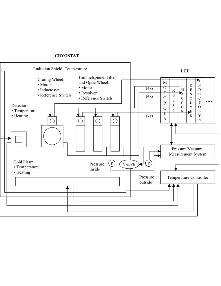
The instrument control electronics governs the function of all moving mechanisms within the cryostat. An overview of the instrument control electronics is shown in figure 6. A motor controller controls the four cryogenic motors which allow the observer to choose the grating, choose the filter, select an appropriate spatial scale, and select a sky setting for the Himmelspinne. The grating wheel is equipped with a high resolution cryogenic encoder with 2 arc second angular resolution. The encoder signal is fed back to the motor controller, which can position the gratings with an accuracy better than 0.2 pixels. The operator can offset the spectra on the detector by 1/2 pixel, for proper Nyquist sampling of the spectra. The motors from the Himmelsspinne, the optic wheel and the filter wheel are equipped with resolvers. All cryogenic moving mechanisms are fitted with reference switches whose signals are fed back to the motor controller. In addition, the instrument control electronics includes temperature sensors which measure the temperatures inside the cryostat at various critical locations. The readout from the vacuum gauges is also reported to the control computer.
 |
5 Instrument Performance
The SPIFFI instrument is designed to maintain a very high optical throughput ( 32 %) at wavelengths of 1.1 m to 2.45 m. Since all optics, including the image slicer, is cooled down to 77 K, the thermal background from the instrument is negligible compared to the contribution from the telescope and the sky. While the K-band instrument performance is mostly limited by the thermal emission from the telescope and the sky, J- and H-band observations are limited by the specifications of the Rockwell HAWAII detector. The final sensitivity of SPIFFI will highly depend on the seeing conditions, the performance of the adaptive optics system MACAO, and the brightness of the sky, especially the OH lines, during observation. Therefore the following numbers (tables 1 and 2) should only give the reader a rough indication of the sensitivity of SPIFFI when operated under normal seeing conditions, and when taking advantage of the adaptive optics.
| J-band | H-band | K-Band | H&K-band | |
|---|---|---|---|---|
| Point Source Sensitivity [mag] | 21.4 | 20.7 | 18.3 | 19.3 |
| Surface Brightness Sensitivity [mag/arcsec2] | 20.2 | 19.5 | 17.1 | 18.1 |
| H-band | K-Band | H&K-band | |
|---|---|---|---|
| Point Source Sensitivity [mag] | 20.7 | 19.6 | 20.5 |
| Surface Brightness Sensitivity [mag/arcsec2] | 15.0 | 14.2 | 15.0 |
The sensitivity numbers were calculated for a spectral resolution of R = 4200 in J- and H-band, R = 4400 in K-band and R = 1900 in H&K-band, on source integration time of 1 hour, signal-to-noise ratio of 3 per spectral channel, a dark current of 0.1 electrons/s and a read noise of 8 electrons. The numbers for H-band observations include OH-avoidance techniques. For typical seeing limited observations we assume the large image scale with 0.25 arcsec / pixel image scale and a seeing where 50 % of a point source flux is within 0.7 arcsec. The sensitivity numbers for adaptive optics assisted observations were derived for the small image scale with 0.025 arcsec / pixel and a Strehl ratio of 50 %.
References
- [1] Weitzel L., Krabbe A., Kroker H., Thatte N., Tacconi-Garman L. E., Cameron M., and Genzel R., “3D: The next generation near-infrared imaging spectrometer”, Astronomy and Astrophysics Supplement Series, 119, 531, 1996
- [2] Tecza M., Thatte N. A., Krabbe A., and Tacconi-Garman L. E., ”SPIFFI: a high-resolution near-infrared imaging spectrometer”, Proceedings of SPIE, 3354, 394, 1998
- [3] Hofmann R., Brandl B., Eckart A., Eisenhauer F., and Tacconi-Garman L. E., “High-angular-resolution NIR astronomy with large arrays (SHARP I and SHARP II)”, Proceedings of SPIE, 2475, 192, 1995
- [4] Thatte N., Tecza M., Eisenhauer F. et al., “SINFONI: a near-infrared AO-assisted integral field spectrometer for the VLT”, Proceedings of SPIE, 3353, 704, 1998
- [5] Tecza M., Thatte N., Eisenhauer F., Mengel S., Röhrle C., and Bickert K., “The SPIFFI image slicer: Revival of image slicing with plane mirrors”, Proceedings of SPIE, accepted, 2000
- [6] Hodapp K.-W., Hora J. L., Hall D. N. et al., “The HAWAII Infrared Detector Arrays: testing and astronomical characterization of prototype and science-grade devices”, New Astronomy, 1, 177, 1996
- [7] Eisenhauer F., Tecza M., Thatte N., Mengel S., Hofmann R., and Genzel R., “Near-Infrared-Spectroscopy with Extremely Large Telescopes: Integral-Field- versus Multi-Object-Instruments”, ESO Conference and Workshop Proceedings, 57, 292, 2000
- [8] Meyer M., Finger G., Mehrgan H., Nicolini G., and Stegmeier J., “ESO infrared detector high-speed array control and processing electronic IRACE”, Proceedings of SPIE, 3354, 134, 1998