Search for interactions between ejections of GRS 1915+105 and its environment
Abstract
To unravel the effect of likely interactions between the energetic ejections of the galactic superluminal source and its surrounding interstellar medium, we observed its environment. Two IRAS sources are symmetrically placed with respect to , and are aligned with the sub-arcsec ejections of this source. We analyzed these two sources and through near-infrared, millimeter and centimeter wavelengths. The evidence for these regions being interaction zones seems inconclusive.
KEYWORDS: Stars: individual: GRS 1915+105 – HII regions – ISM: individual objects: IRAS 19124+1106, IRAS 19132+1035 – ISM: jets and outflows – X-rays: stars
1. Introduction
The first known galactic superluminal source is a highly energetic and relativistically ejecting source. Consequently one wonders if there is an observable interaction when the frequently ejected plasma clouds collide at relativistic velocities with the interstellar medium, or heat molecular clouds surrounding this source. Indeed, the ensemble of ejections of such a microquasar must have an effect on its environment, as it is the case for the well-known ejecting source . Therefore, we undertook a comprehensive study of the environment of at near-infrared, mid-infrared, radio centimeter and millimeter wavelengths. Here some of the radio observations are described and discussed; the reader can refer to Chaty et al. (2000, hereafter C00) for a complete description of the study.
2. The observations: two axisymmetric sources
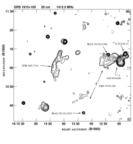
The region surrounding was inspected and described by Rodríguez and Mirabel (1998, hereafter RM98). This search was performed at cm, with the VLA (Very Large Array) of NRAO111The National Radio Astronomy Observatory is operated by Associated Universities, Inc., under cooperative agreement with the USA National Science Foundation, in C-configuration, giving a resolution of . The resulting map is shown in Figure 1. They discovered that there were two axisymmetrically placed continuum radio sources, each located at from , and coincident with IRAS sources. Their positions are given in Table 1. Furthermore, the position angle of these sources is from , very similar to the one of the well studied sub-arcsec radio-ejections from (). In order to interpret the radio data, we remind here that the angle between the ejections and the line of sight towards is , that the South component is approaching us, and the North component is receding (Mirabel and Rodríguez, 1994; Fender et al., 1999).
Although these two sources could be a chance alignment, the striking point-symmetric position of these two clouds suggests that they result from an association with the high-energy source .
| Source | J2000.0 coord. | gal. coord. |
|---|---|---|
| GRS 1915+105 | ||
| IRAS 19124+1106 | ||
| IRAS 19132+1035 | ||
2.1. Centimeter wavelength observations
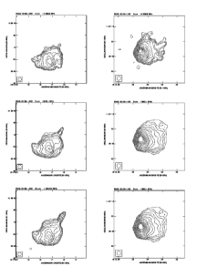
High-resolution maps of the two continuum radio sources have been obtained with the VLA (RM98). These maps are shown in the Figure 2. Concerning the North lobe, the centimeter map shows that it resembles to a common cometary H II region, but it also shows a shockwave structure to the South, e.g. to the direction of . For the South lobe, the centimeter map shows to the northwest a non-thermal jet, pointing along the direction of . The flux densities of this jet are , and respectively at and , showing a spectral index of . Furthermore, the South lobe shows a sharp edge to the South, which could be either a bow shock, or an ionization front in the H ii region. The following discussion emphasizes these two striking features of the South lobe.
2.2. Millimeter wavelength observations
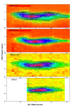
We used the IRAM (Institut de Radio Astronomie Millimétrique) 30-m radio telescope, located on Pico Veleta, near Granada, Spain. The details of observations are described in C00, and the results for are shown in Figure 3. The OFF position (position switching) was chosen at (, ) from . The main results are that i) the density profile of the cloud exhibits an asymmetric velocity distribution, ii) the maximum of the profile is closer to the counter-jet for high density tracers (compare e.g. 12CO 2-1 to the CS 2-1 transition), and iii) there are two maxima in the 12CO 2-1 transition and only one in the others. The other main result is that we detected a 4- SiO 2-1 line, localized on the position of the counter-jet.
All these facts could indicate the presence of an interaction, although they do not constitute a clear proof thereof. Is there an association, or the two H ii regions are point-symmetric by chance?
3. Discussion and Conclusion
There is a possibility that these two IRAS sources received energy from through shocks initiated by plasma clouds ejected by and colliding with H ii regions, creating the non-thermal jet seen in the South lobe. There is also a possibility that the relativistic ejecta have induced star formation, and this could have created the non-thermal jet as a Herbig-Haro-like feature. However, we consider this last possibility as unlikely because of the timescale of the different phenomena.
The other possibility is that these two IRAS sources have nothing to do with : the alignment could be a background coincidence. It is worthwhile to remember that there are two point-symmetric sources, and furthermore the IRAS fluxes and the molecular lines show that the two IRAS sources are in our Galaxy (RM98). This decreases the probability of a background coincidence.
Although our observations spanned in a large range of wavelengths (C00), and there are some striking facts, we can not clearly prove any association between and the two IRAS sources.
ACKNOWLEDGEMENTS
S.C. acknowledges support from grant F/00-180/A from the Leverhulme Trust, and is grateful to C.A. Haswell for improving the language of the manuscript.
REFERENCES
Chaty, S., Rodríguez, L.F., Mirabel I.F. et al., 2000, A&A submitted
Fender, R. et al., 1999, MNRAS, 304, 865
Mirabel I.F. and Rodríguez, L.F., 1994, Nat, 371, 46
Rodríguez, L.F. and Mirabel I.F., 1998, A&A, 340, L47