BEAM COUPLING IMPEDANCES OF OBSTACLES
PROTRUDING INTO BEAM PIPE
Abstract
The beam coupling impedances of small obstacles protruding inside the vacuum chamber of an accelerator are calculated analytically at frequencies for which the wavelength is large compared to a typical size of the obstacle. Simple formulas for a few important particular cases, including both essentially three-dimensional objects like a post or a mask and axisymmetric irises, are presented. The analytical results are compared and agree with three-dimensional computer simulations. These results allow simple practical estimates of the broad-band impedance contributions from such discontinuities.
I Introduction
Due to high currents in modern accelerators and colliders, even contributions from small discontinuities of the vacuum chamber to the impedance budget of the machine have to be accounted for. Numerous pumping holes — a few hundred per meter — in the vacuum screen of the Large Hadron Collider (LHC) can serve as an example. Their total contribution to the machine impedance in the initial design was calculated [1, 2] using the Bethe theory of diffraction of EM-waves by a small hole in a metal plane [3], and found to be dangerously large, close to the beam instability threshold. Proposed design changes reduced the impedance more than an order of magnitude [4]. The method’s basic idea is that the hole, at frequencies where the wavelength is large compared to the typical hole size, can be replaced by two induced dipoles, an electric and a magnetic one. Using essentially the same idea, the method was extended for arbitrary-shaped small discontinuities on the pipe of an arbitrary-shaped cross section [5]. The impedance calculation for a given small discontinuity was therefore reduced to finding its electric and magnetic polarizabilities. Analytical results in this direction have been obtained for axisymmetric obstacles [6], as well as for holes and slots: circular [3] and elliptic [7] holes in a zero-thickness wall, circular [8] and elliptic [9] holes in a thick wall, various slots [10], and a ring-shaped cut [11].
In a recent paper [12] the method was applied to calculate the coupling impedances of obstacles protruding inside the beam pipe, like a narrow post or a mask intercepting synchrotron radiation. Formulas derived make practical estimates very simple. Numerical simulations required to obtain similar results are necessarily 3D ones, and therefore are rather involved. This statement is generally applicable for any small discontinuities, but especially for those protruding into the vacuum chamber. Below we list the analytical results [12] and compare them with simulations.
II General Solution
The longitudinal coupling impedance of a small discontinuity on the wall of a circular beam pipe of radius is [1]
| (1) |
when the wavelength is large compared to the obstacle size. Here is the impedance of free space, is the wave number, and are the electric and magnetic polarizabilities of the discontinuity. The transverse impedance is proportional to the same combination of polarizabilities , and the real part of the impedance is small at such frequencies (see [5, 4] for detail, as well as for other chamber cross sections). Let the obstacle shape be a half-ellipsoid with semiaxis in the longitudinal direction (along the chamber axis), in the radial direction, and in the azimuthal one. When , the obstacle is small and the Bethe approach can be applied. To find the polarizabilities, one needs to calculate the induced electric dipole moment of the obstacle illuminated by a homogeneous radial electric field , and the magnetic dipole moment when it is illuminated by an azimuthal magnetic field . This problem was reduced [12] to the well-known problem for an ellipsoid immersed in a homogeneous field, e.g., [7]. Adding obvious symmetry considerations, we get
| (2) |
where
| (3) |
and is given by Eq. (3) with and interchanged.
III Post and Mask
In the case , we have an ellipsoid of revolution, and the integral in Eq. (3) can be expressed in terms of the hypergeometric function :
| (4) |
and
| (5) |
In the limit , which corresponds to a pin-like obstacle, is much larger than . Note that in this limit , where is the volume occupied by the obstacle (and subtracted from that occupied by the beam magnetic field), somewhat similarly to the axisymmetric case [6]. These results give us a simple expression for the inductive impedance of an narrow pin (post) of height and radius , , protruding radially into the beam pipe:***One could use the known result for the induced electric dipole of a narrow cylinder parallel to the electric field [13]. It will only change in Eq. (6) to .
| (6) |
One more particular case of interest here is , i.e. a semispherical obstacle of radius . From Eqs. (4)-(5) the impedance of such a discontinuity is
| (7) |
which is times that for a circular hole of the same radius in a thin wall [1].
The MAFIA code package [14] was used to compute the impedances of various small protrusions for comparison with analytical results. Calculating wakes due to protrusions is a more difficult task for MAFIA than those due to cavities. One has to either use a long pipe (which leads to a huge mesh since it should be homogeneous along the beam path), or apply a trick with tapers on the pipe ends. The tapers make transitions to a new end pipe with radius , so that the new structure looks like a shallow cavity. The difference of wakes computed with and without a protrusion gives us its contribution. We used the second approach with pipes from to long and meshes up to points. Simulation results are usually higher than the analytical ones, but go down as a finer mesh is used. Figure 1 gives some comparison for a semisphere.

Another practical result that can be derived from the general solution, Eqs. (2)-(3), is the impedance of a mask intended to intercept synchrotron radiation. We put , so that our model mask has the semicircular shape with radius in its largest transverse cross section. Then the integral in Eq. (3) is reduced to
and we further simplify the result for two particular cases.
The first one is the thin mask, , in which case , and again it dominates the magnetic term, . The coupling impedance for such an obstacle — a half-disk of radius and thickness , , transverse to the chamber axis — is therefore
| (8) |
where the next-to-leading term is shown explicitly.
In the opposite limit, , which corresponds to a long (along the beam) mask, the leading terms cancel each other. As a result, the impedance of a long mask with length and height , , is
| (9) |
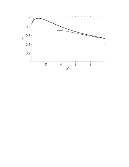
which is relatively small due to the “aerodynamic” shape of this obstacle, in complete analogy with results for long elliptic slots [1, 2, 10]. Figure 2 shows the impedance of a mask with a semicircular transverse cross section of radius versus its normalized half-length, . The comparison with the asymptotic approximations Eqs. (8) and (9) is also shown. One can see that the asymptotic behavior (9) starts to work well only for very long masks, namely, when . Figure 2 demonstrates that the mask impedance depends rather weakly on the length. Even a very thin mask () contributes as much as times the semisphere () impedance, Eq. (7), while for long masks the impedance decreases slowly: at , it is still 0.54 of that for the semisphere.
In practice, however, the mask has usually an abrupt cut toward the incident synchrotron radiation, so that it is rather one-half of a long mask. Numerical simulations show that the low-frequency impedances of a semisphere and a half-semisphere of the same depth — which is a relatively short mask — are almost equal (within the errors), and close to that for a longer half-mask. From these results one can conclude that a good estimate for the mask impedance is given simply by Eq. (7). One more interesting observation is that the inductances found numerically for two half-semispheres — one with a cut toward the incident beam and the other, mirrored — differ by 3%, while they have to be equal as was proven analytically [15].
IV Axisymmetric Iris
Following a similar procedure one can also easily obtain the results for axisymmetric irises having a semi-elliptic profile in the longitudinal chamber cross section, with depth and length along the beam. For that purpose, one should consider the limit in Eq. (3) to calculate polarizabilities and per unit length of the circumference of the chamber transverse cross section. The broad-band impedances of axisymmetric discontinuities have been studied in [6], and the longitudinal coupling impedance is given by
| (10) |
quite similar to Eq. (1). As , the integral , and is expressed in elementary functions as
It gives us immediately
| (11) |
and the resulting impedance of the iris of depth with the semielliptic profile is simply
| (12) |
which proves to be independent of the iris thickness . The same result has been recently obtained using another, direct method [16].
One should emphasize that in Eq. (11) is just an iris cross-section area (with negative sign), which is correct for any small axisymmetric discontinuity, as was pointed out in [6]. However, calculating in general is not easy: a conformal mapping was constructed for that purpose in [6] for irises (as well as for chamber enlargements) having a trapezoid (or rectangular, or triangular) profile. An interesting fact is that the leading behavior for thin irises of all shapes is exactly the same as Eq. (12).
In fact, the same approach can be applied here. The conformal mapping from the upper half-plane into with the boundary including the iris having a semielliptic profile is given by
We need an inverse mapping, but, fortunately, it is enough to find its asymptotic behavior at large and [6], which is
The ratio of the coefficients of the second and first terms on the RHS is , cf. [6], which leads us exactly to the result for in Eq. (11). It is even easier for the particular case , when the iris has a semicircular profile of radius . The explicit conformal mapping for this case is very simple, . The comparison of the second and first terms on the RHS gives us , in agreement with Eq. (11).
V Summary
Analytical expressions of the impedances for both 3D and axisymmetric small obstacles protruding inside a beam pipe are obtained, and they agree well with numerical results. These formulas greatly simplify calculations of the broad-band contributions to the coupling impedances from such discontinuities, especially in the 3D case.
The present approach does not work for enlargements of the vacuum chamber. However, existing analytical results for holes and slots [1, 2, 4, 5], as well as for axisymmetric enlargements [6], cover this case quite well.
Stimulating discussions with Dr. R.L. Gluckstern and Dr. F.L. Krawczyk are gratefully acknowledged.
REFERENCES
- [1] S.S. Kurennoy, Part. Acc. 39, 1 (1992).
- [2] R.L. Gluckstern, Phys. Rev. A 46, 1106, 1110 (1992).
- [3] H.A. Bethe, Phys. Rev. 66, 163 (1944).
- [4] S.S. Kurennoy, Part. Acc. 50, 167 (1995).
- [5] S.S. Kurennoy, R.L. Gluckstern, and G.V. Stupakov, Phys. Rev. E 52, 4354 (1995).
- [6] S.S. Kurennoy and G.V. Stupakov, Part. Acc. 45, 95 (1994).
- [7] R.E. Collin, Field Theory of Guided Waves (IEEE Press, NY, 1991).
- [8] R.L. Gluckstern and J.A. Diamond, IEEE Trans. MTT 39, 274 (1991).
- [9] B. Radak and R.L. Gluckstern, ibid. 43, 194 (1995).
- [10] S.S. Kurennoy, Report SSCL-636, Dallas (1993).
- [11] S.S. Kurennoy, IEEE Trans. MTT 44, 1109 (1996).
- [12] S.S. Kurennoy, Phys. Rev. E. 55, 3529 (1997).
- [13] L.D. Landau and I.M. Lifshitz, Electrodynamics of Continuous Media (Pergamon Press, Oxford, 1960), §3.
- [14] M. Bartsch et al. Computer Physics Comm. 72, 22 (1992).
- [15] R.L. Gluckstern and B. Zotter, CERN LEP-Note 613 (1988); S.A. Heifets, Report SLAC/AP-79 (1990).
- [16] R.L. Gluckstern and S.S. Kurennoy, Phys. Rev. E. 55, 3533 (1997).