Performance Evaluation of Beyond Diagonal RIS under Hardware Impairments
Abstract
Beyond diagonal reconfigurable intelligent surface (BD-RIS) improves the traditional reconfigurable intelligent surface (RIS) architecture functionality by interconnecting elements for advanced wave control. However, real-world implementations face hardware imperfections, such as impedance mismatches and varactor nonidealities, which can degrade overall system performance. In this paper, we propose three hardware impairment models that directly affect the BD-RIS scattering matrix structure and evaluate their impact on the channel estimation accuracy using the normalized mean square error (NMSE) as a performance metric. The proposed impairment models consider imperfections affecting self-impedances, mutual impedances, or both. Our results reveal how each impairment type degrades the system performance, allowing us to identify scenarios where the traditional RIS can outperform the BD-RIS.
keywords:
Beyond diagonal RIS, hardware impairments, channel estimation.1 Introduction
In a typical communication system, the transmitted signal suffers from several impairments due to the surrounding environment, including attenuation and scattering, which is generally caused by multipath propagation, one of the main limiting factors in this wireless communication system. An emerging technology capable of mitigating these effects and improving propagation conditions is RIS which is a man-made surface composed of electromagnetic materials that consists of a 2D array with many low-cost passive elements that can control the electromagnetic properties of radio-frequency waves, such as phase, amplitude, and frequency [1, 2, 3]. In general, the propagation of electromagnetic waves in wireless communication channels is not controlled between the transmission and reception processes. However, the RIS can "reprogram" the channel during this stage. Classical RIS architectures consider each element independent of the others, i.e., no interconnection among elements exists. This design translates into the signal model, where the scattering matrix has a diagonal structure. As a result, some limitations arise, such as limited beamforming capabilities and restricted degrees of freedom to control the direction of signal reflection[4].
Recent studies have introduced beyond diagonal reconfigurable intelligent surface (BD-RIS) to overcome conventional RIS’s limitations and enhance system performance [5]. In BD-RIS architectures, the reflecting elements are intentionally interconnected, leading to a non-diagonal signal model matrix. More precisely, in the BD-RIS architecture, the connections are primarily defined as [6, 7, 8, 9, 10, 11] 1) group-connected, where only a portion of the RIS elements are interconnected, leading to the signal model a block-diagonal matrix as scattering matrix, and 2) fully-connected, which represents the design that all RIS elements are connected. In this case, the signal model scattering matrix is complete, i.e., with all non-zero entries. This non-diagonal design of the scattering matrix provides additional degrees of freedom and enables a more flexible control over the signal properties. This includes joint manipulation of phase and amplitude and the ability to create more reflection patterns, which, in specific scenarios, allow BD-RIS to outperform the conventional diagonal RIS.
Despite the promising theoretical performance of BD-RIS, most existing studies are still based on idealized models with perfect operating conditions. In many cases, however, such models do not fully capture the practical imperfections possible in real-world implementations, such as impedance mismatches and losses in the passive interconnected components of the internal circuits of the BD-RIS structure. These limitations highlight the need for more realistic performance evaluations considering physical/electronic impairments.
In this paper, we evaluate the performance of BD-RIS-assisted communication systems in the presence of circuit-based hardware impairments. We start from the baseline signal model of [9] by including the hardware impairment models and assess the solution of [9] under imperfections. We consider three hardware impairment models directly affecting the self-impedances, mutual impedances, or both. Simulation results show how these imperfections affect the channel estimation performance when state-of-the-art algorithms are used.
2 Notation and properties
To facilitate the understanding of the material presented throughout the paper, we define the key mathematical notations and properties used. Scalars are denoted by non-bold lowercase letters, such as , column vectors are denoted by bold lowercase letters, such as , and matrices are represented by bold uppercase letters, such as . represents an identity matrix of size , while stands for a all-ones matrix of size . The superscripts and denote the transpose, conjugate, and conjugate transpose, respectively. The operator refers to the Frobenius norm of a matrix or tensor, and denotes the expectation operator. The operator converts a vector into a diagonal matrix. From a set of matrices , with , we can construct a block diagonal matrix as . Moreover, the operator converts a matrix to a column vector by stacking its columns on top of each other, while the operator unvec reverses this operation, restoring the matrix . The symbols , , , and denote the outer product, the Hadamard product, the Kronecker product, and the Khatri-Rao product (also known as the column-wise Kronecker product), respectively. Some useful properties that will be exploited in this paper are the following.
| (1) | ||||
| (2) | ||||
| (3) |
where the vectors and matrices involved have compatible dimensions in each case, and is a permutation matrix. The Khatri-Rao product of the matrices and , is defined as
| (4) |
where and , are the -th column of and , respectively, for .
3 System Model
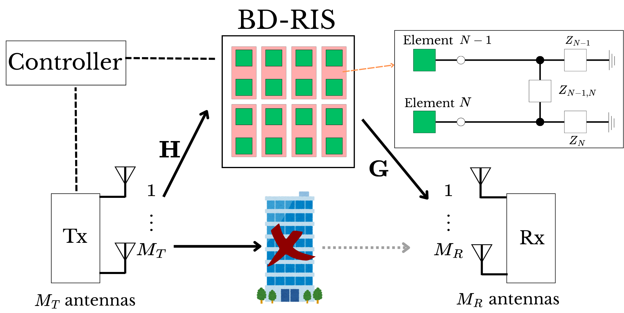
We consider the system model described in [12], i.e., a multiple-input multiple-output (MIMO) communication system assisted by a BD-RIS composed of elements, divided into groups, each of size , i.e., . The transmitter (Tx) and the receiver (Rx) have and antennas, respectively. The direct link (TX-RX) is assumed to be blocked for convenience. The transmission duration is over time-slots, from which the transmitted pilots are defined as . The received signal on the -th transmitted time slot is given by
| (5) |
where, and are the -th block matrix of the TX-RIS and RIS-RX channels, i.e., and . represents the BD-RIS scattering matrix of the -th group at the -th time slot.
To model a possible real-world hardware imperfection affecting the impedances, we consider different types of impairments that are given by a matrix in which is detailed in Section 4. For the sake of convenience, we consider that hardware impairment is constant over the transmission of the time slots. Thus, the real observed BD-RIS scattering matrix, at the -th time slot, can be denoted as
| (6) |
where is the ideal BD-RIS scattering matrix at the -th time slot, for . Hence, the signal received in the -th time slot can be expressed as
| (7) | ||||
| (8) |
Using the property (1), as demonstrated in [12], the noise free received signal can be written as
| (9) |
where . Applying property (4), collecting the time slots in a single observation vector, and removing the summation, we obtain the following equivalent expression
| (10) | ||||
where is the combined BD-RIS impaired scattering matrix and the transmitted pilot. The matrix is built from the vectorized, group-wise impaired scattering matrices, i.e., for . The combined channel vector is defined as , for . Then the authors in [12] formulates the following linear least squares (LS) estimation problem
where its the ideal combined BD-RIS scattering matrix with the pilot matrix . Since is known at the receiver, it can be optimally designed, from which . As solution for the LS problem, the authors in [12] derived a matched filter, i.e.,
| (11) |
The resulting estimate aggregates all the BD-RIS groups and can be approximately expressed as
| (12) |
To recover a unique solution for , the number of pilot symbols must satisfy [12]. Also, the authors of [12] proposed a decoupling method that exploits the structure of (12). However, the solution discussed in [12] considers the ideal scattering matrix , thus the matched filter in (11) is efficient. However, the scattering matrix may be non-ideal, containing impairments, as shown in (6). Thus, the solution in (11) translates to
| (13) |
where . In this context, our goal is to evaluate the accuracy of channel estimation for BD-RIS by taking into account the mismatch between the ideal scattering matrix and the actual imperfect scattering matrix . To our knowledge, this is the first paper that studies the impact of these hardware imperfection models on the channel estimation performance for BD-RIS-assisted communication systems. In the following, we describe three hardware impairment models and their implications on the signal model.
4 BD-RIS hardware impairments
In this section, we discuss the possible sources of the impairments that can affect RIS, especially the BD-RIS. Later, we discuss the impact of those impairments on the signal model in three different ways. We summarize the source of BD-RIS impairments as:
-
•
Impedance mismatch: Variations in the physical or electrical properties of the RIS elements can lead to unintended impedance values, affecting individual self-impedances and/or mutual impedances.
- •
-
•
Thermal and environmental effects: Temperature fluctuations, humidity, and mechanical stress can alter the electrical characteristics of the circuit components over time, leading to dynamic impairments.
These practical effects highlight the importance of incorporating realistic models, such as [15], into analyzing BD-RIS-assisted communication systems, enabling a more accurate performance evaluation and designing more robust solutions. To evaluate the actual performance of the proposed system, we consider the presence of three different impairment models that can affect the scattering matrix of the BD-RIS. In all cases, the impairment (error) matrix is represented by the matrix . Then, the real scattering matrix, on the time slot , is described by Eq. (6). This model allows us to individually select which scattering matrix elements have their amplitude and phase distorted. Note that if a given element is not affected, the corresponding entry in is set to .
Given the group-connected architecture of the BD-RIS, the global impairment matrix is defined as
where each block represents the impairment affecting group of the BD-RIS. To maintain a physical reciprocity of energy, all impairment groups preserve the Hermitian symmetry of the system when applicable, which means that , i.e., for . We consider three types of hardware impairments that may affect the interconnections of the BD-RIS, as follows.
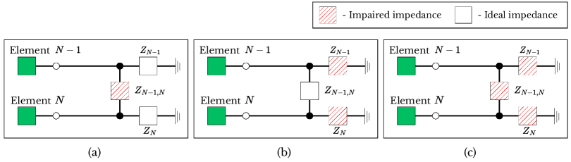
4.1 Type 1
The first impairment type corresponds to assuming that only the mutual impedances interconnecting the BD-RIS elements are affected. This corresponds to assuming the off-diagonal elements of the impairment matrix are composed of random error terms while the main diagonal ones are equal to 1. In other words, the Type impairment affects only the off-diagonal elements of the scattering matrix . Mathematically, the Type impairment matrix is constructed as follows
where and represent the amplitude and phase distortions, respectively, and for . For the Type impairment, the maximum number of affected impedances is , corresponding to the off-diagonal entries.
4.2 Type 2
In this case, we assume that only the self-impedances of the BD-RIS elements are affected. This corresponds to assuming the main diagonal elements of the impairment matrix are composed of random error terms while the off-diagonal ones are equal to 1. Hence, the Type impairment affects only the main diagonal elements of the scattering matrix . The matrix for the Type impairment is then given as
for . In this case, up to impedances can be affected, corresponding to the diagonal of the matrix.
4.3 Type 3
In this impairment type, we assume all the impedances (self and mutual) connecting the BD-RIS elements are affected, which corresponds to a fully random impairment matrix , affecting all the scattering elements. In this case, we have
The maximum number of potentially affected impedances in this case is .
5 Simulation Results
In this section, we evaluate the impact of the three proposed impairment models on the performance of the BD-RIS-assisted communication system. The analysis is based on Monte Carlo simulations over independent trials. A new channel and a new impairment matrix are generated in each realization, allowing us to assess the average performance under different distortion conditions. The metric used for performance evaluation is the NMSE of the estimated combined channel , defined as:
where denotes the vectorized combined channel at the -th trial. The BD-RIS training matrix is constructed using the orthogonal design proposed in [9]. We assume orthogonal pilot sequences constructed from a truncated discrete Fourier transform (DFT) matrix , such that . The pilot overhead is given by , where the group size plays a crucial role. As changes, the number of pilot symbols required also varies, even when the total number of RIS elements remains fixed. In all experiments, we assume an RIS panel with elements, and antennas at the transmitter and receiver, respectively. The caption ‘max’ on Figs. 3-7 represents the maximum number of impedances that can be affected, while the term ‘affected’ refers to the actual number of affected impedances on that experiment.
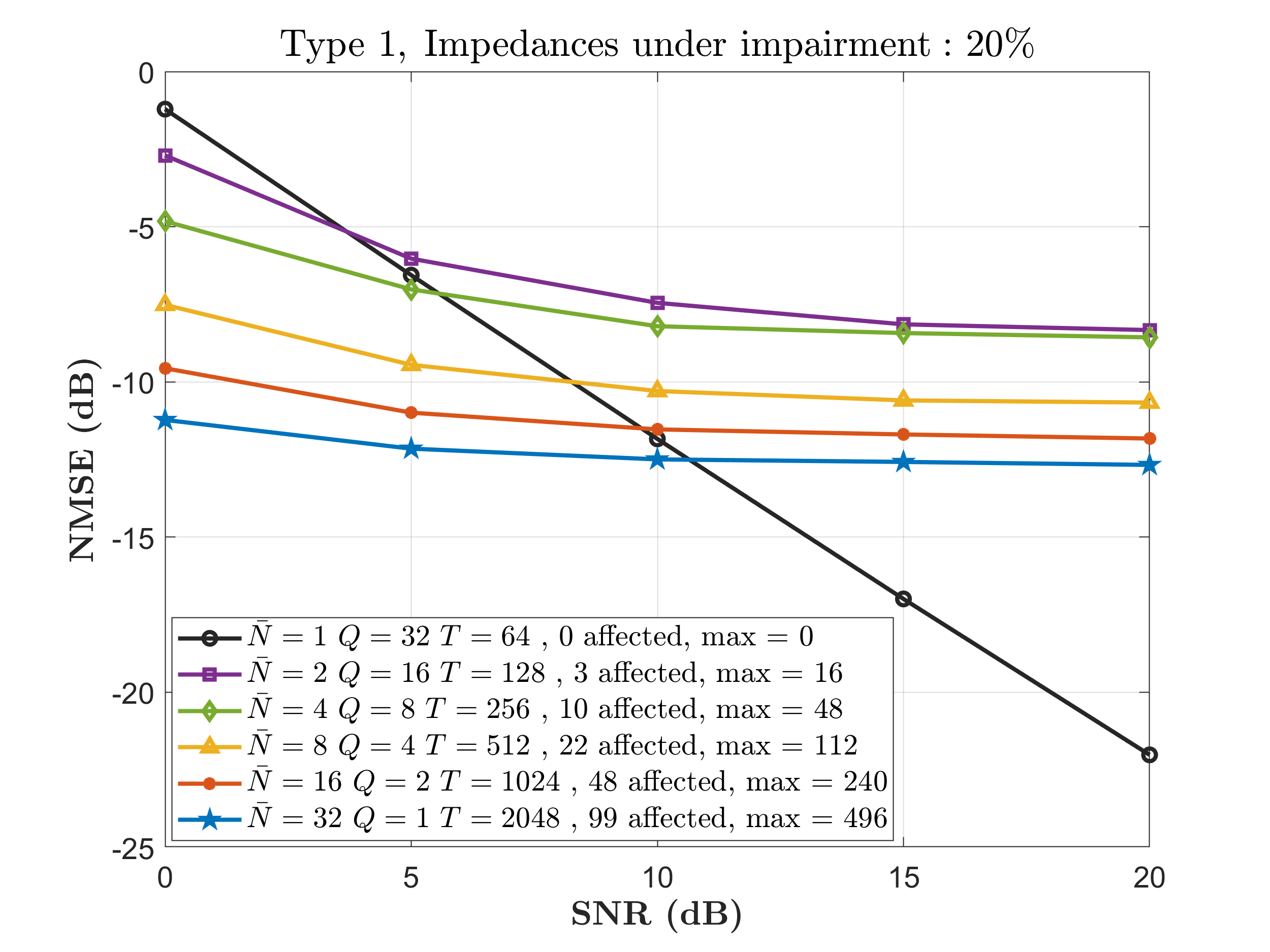
In Figure 3, we compare the channel estimation NMSE performance by assuming a total of impedances affected for the Type impairment. Since the total number of affected elements of is given by , as the group size increases, more disturbed elements are present in . We observe that the additive noise dominates the channel estimation performance for low signal to noise ratio (SNR) values, between approximately dB and dB. In other words, the effect of the hardware impairment is relatively minor compared to the noise power in this case. As a result, the BD-RIS performance does not degrade significantly, and it can still outperform a conventional diagonal RIS (). However, as the SNR increases, the influence of noise diminishes, and the effect of the impairment becomes dominant. This leads to an NMSE performance saturation in BD-RIS configurations with many affected off-diagonal elements. On the other hand, the conventional RIS (when ) is not affected by the impairment Type since this impairment, as shown in Figure 2, only affects off-diagonal elements.


In Figures 4 and 5, we compare the NMSE performance of the ideal RIS scenario, i.e., the case when the impairment matrix is , thus none element of is affected, with the impairment Type (Fig. 4) and Type (Fig. 5), respectively. We assume that of the impedances are affected. As expected, in both cases, there is a consistent performance gap between the ideal and impaired cases in all configurations. However, in Figure 4, this gap decreases as increases. For , the NMSE degradation is more present, while for , the performance loss is significantly reduced. This behavior comes from the fact that even when the same number of impedances are affected, the Type impairment only affects the diagonal elements of the scattering (i.e., the self-impedances, see Fig. 2). In contrast, the Type impairment affects all the elements of .
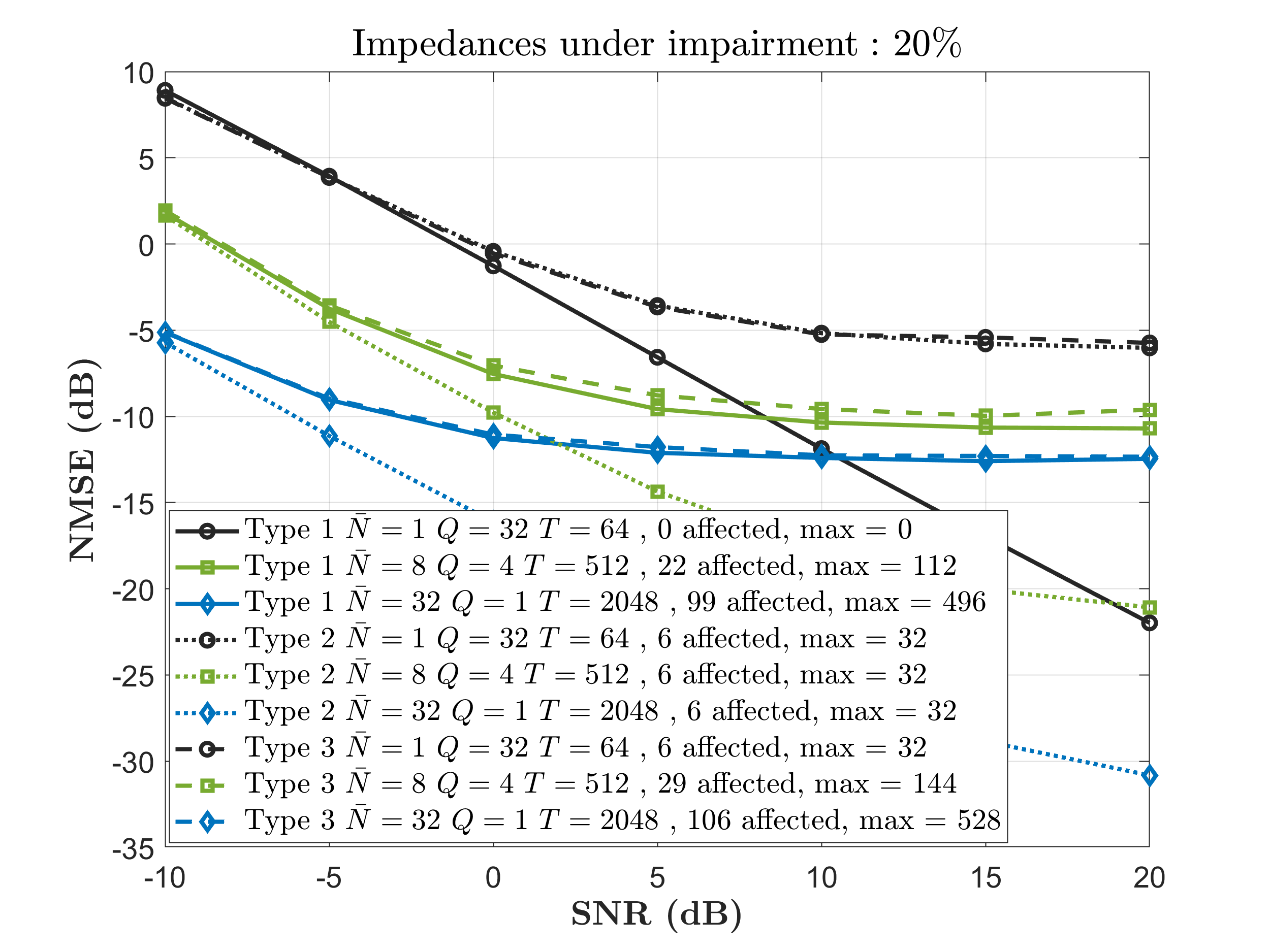
In Figure 6, we compare the three types of impairments by considering that of the BD-RIS impedances are affected. We can observe that, compared to the Type and Type impairments, the Type impairment less significantly affect the channel estimation accuracy. This is explained by the fact that the Type impairment only affects the diagonal elements of the scattering matrix. Thus, it is fixed over elements. In contrast, Type and Type affects up to and , respectively.

In Figure 7, we compare the impact of the three impairment models on the channel estimation accuracy by fixing the SNR at dB and varying the number of affected impedances. As the percentage of affected impedances increases, all impairment types show performance degradation regarding channel estimation accuracy. However, Type impairment consistently leads to lower NMSE values, confirming that it is the least harmful. In contrast, Type 1 and Type 3 produce a more significant degradation, with Type 3 performing slightly worse due to the larger number of affected matrix elements. This experiment highlights how different hardware impairments impact BD-RIS performance depending on where the impairments occur in the scattering structure.
6 Conclusion
This work examined the practical impact of hardware imperfections on beyond diagonal reconfigurable intelligent surface (BD-RIS). By introducing three impairment models on the ideal scattering matrix, we quantified their direct effect on channel estimation accuracy through the NMSE metric. Our results reveal that even a modest impairment level (e.g., of affected impedances) can cause significant performance loss. This degradation becomes more pronounced as the SNR increases, leading to a growing performance gap compared to the ideal case. The Type and Type impairments produce the most severe degradation due to the capacity of affecting more elements of the scattering matrix in a BD-RIS. As a perspective of this work, we shall investigate methods to estimate the impairment matrix at the receiver. Identifying imperfect/malfunctioning elements is particularly useful in a real-world setup since it would allow us to mitigate their effect when designing the active and passive beamformings or to dynamically select/deactivate BD-RIS elements to optimize the system performance under practical imperfections.
References
- [1] E. Basar, M. Di Renzo, J. De Rosny, M. Debbah, M.-S. Alouini, and R. Zhang, “Wireless communications through reconfigurable intelligent surfaces,” IEEE access, vol. 7, pp. 116 753–116 773, 2019.
- [2] G. T. de Araújo and A. L. F. de Almeida, “Parafac-based channel estimation for intelligent reflective surface assisted mimo system,” in 2020 IEEE 11th Sensor Array and Multichannel Signal Processing Workshop (SAM), 2020, pp. 1–5.
- [3] G. T. de Araújo, A. L. de Almeida, and R. Boyer, “Channel estimation for intelligent reflecting surface assisted mimo systems: A tensor modeling approach,” IEEE Journal of Selected Topics in Signal Processing, vol. 15, no. 3, pp. 789–802, 2021.
- [4] B. Zheng, C. You, W. Mei, and R. Zhang, “A survey on channel estimation and practical passive beamforming design for intelligent reflecting surface aided wireless communications,” IEEE Communications Surveys & Tutorials, vol. 24, no. 2, pp. 1035–1071, 2022.
- [5] H. Li, S. Shen, M. Nerini, and B. Clerckx, “Reconfigurable intelligent surfaces 2.0: Beyond diagonal phase shift matrices,” IEEE Communications Magazine, vol. 62, no. 3, pp. 102–108, 2023.
- [6] S. Shen, B. Clerckx, and R. Murch, “Modeling and architecture design of reconfigurable intelligent surfaces using scattering parameter network analysis,” IEEE Transactions on Wireless Communications, vol. 21, no. 2, pp. 1229–1243, 2021.
- [7] H. Li, S. Shen, and B. Clerckx, “Beyond diagonal reconfigurable intelligent surfaces: From transmitting and reflecting modes to single- , group- , and fully-connected architectures,” IEEE Transactions on Wireless Communications, vol. 22, no. 4, pp. 2311–2324, 2022.
- [8] Li, Hongyu and Shen, Shanpu and Clerckx, Bruno, “A dynamic grouping strategy for beyond diagonal reconfigurable intelligent surfaces with hybrid transmitting and reflecting mode,” IEEE Transactions on Vehicular Technology, vol. 72, no. 12, pp. 16 748–16 753, 2023.
- [9] H. Li, Y. Zhang, and B. Clerckx, “Channel estimation for beyond diagonal reconfigurable intelligent surfaces with group-connected architectures,” in 2023 IEEE 9th International Workshop on Computational Advances in Multi-Sensor Adaptive Processing (CAMSAP), 2023, pp. 21–25.
- [10] A. L. F. de Almeida, B. Sokal, H. Li, and B. Clerckx, “Channel estimation for beyond diagonal ris via tensor decomposition,” IEEE Transactions on Signal Processing, pp. 1–15, 2025.
- [11] H. Li, S. Shen, Y. Zhang, and B. Clerckx, “Channel estimation and beamforming for beyond diagonal reconfigurable intelligent surfaces,” IEEE Transactions on Signal Processing, vol. 72, pp. 3318–3332, 2024.
- [12] B. Sokal, Fazal-E-Asim, A. L. F. de Almeida, H. Li, and B. Clerckx, “A decoupled channel estimation method for beyond diagonal ris,” in 2024 58th Asilomar Conference on Signals, Systems, and Computers, 2024, pp. 1395–1399.
- [13] L. C. d. P. Pessoa, G. T. d. Araújo, P. R. B. Gomes, and A. L. F. d. Almeida, “Irs-assisted communications under practical channel estimation and hardware model,” in Anais do XXXIX Simpósio Brasileiro de Telecomunicações e Processamento de Sinais (SBrT), Fortaleza, CE, Brasil, setembro 2021, pp. 1–6.
- [14] P. R. B. Gomes, G. T. de Araújo, B. Sokal, A. L. F. d. Almeida, B. Makki, and G. Fodor, “Channel estimation in ris-assisted mimo systems operating under imperfections,” IEEE Transactions on Vehicular Technology, vol. 72, no. 11, pp. 14 200–14 213, 2023.
- [15] P. R. B. Gomes, G. T. de Araújo, B. Sokal, A. L. F. de Almeida, B. Makki, and G. Fodor, “Tensor-based channel estimation for ris-assisted communications with non-ideal phase shift responses,” in 2022 Workshop on Communication Networks and Power Systems (WCNPS), 2022, pp. 1–6.