Circulators based on Coupled Quantum Anomalous Hall Insulators and Resonators
Abstract
Integrated plasmonics is advancing rapidly, enabling a wide range of functionalities to be incorporated onto a single chip. Applications span information processing, computation, quantum sensing, and dark-matter detection. This progress has driven the development of integrated non-reciprocal devices, which are essential for preventing unwanted feedback that can degrade system performance. While non-reciprocal devices have been realized in edge magnetoplasmon materials via classical interference effects, their operation is often complicated by a dependence on input power. Here, we demonstrate that topological circulators utilizing asymmetric coupling offer improved input power range, isolation, and insertion loss. In this configuration, non-reciprocal behavior arises from the coupling between a chiral edge magnetoplasmonic resonator and LC resonators, leading to non-Hermitian dynamics. The coherent photon-plasmon interaction enables a circulator with up to 50 dB of isolation across a broad range of excitation intensities. This is the first experimental demonstration showing that magnetic topological insulators can support the study of chiral plasmonic cavity quantum electrodynamics at radio frequencies, underscoring their potential to enable chip-scale quantum-classical interfaces in superconducting quantum information processing systems.
- Keywords
-
Non-reciprocal devices, Topological Insulator, Cavity Quantum Electrodynamics
I Introduction
The chiral, dissipationless nature of the edge magnetoplasmon makes it a promising candidate for advancing chip-scale non-reciprocal devices at quantum-classical interfaces [1, 2, 3]. Although the propagation of edge magnetoplasmons (EMPs) has been extensively studied in quantum Hall (QH) systems [4, 5, 6], their coupling to an external device within the regime of cavity quantum electrodynamics (cQED) remains largely unexplored. It has recently been pointed out that the QH edge magnetoplasmon state could be valuable for measuring and controlling solid-state qubits, due to its inherently high characteristic impedance, quantized as with the Landau-level filling factor[7, 8]. As a result, high-impedance plasmonic transmission lines and resonators are predicted to achieve strong coupling to external two-level systems, such as spin qubits, thereby enabling exploration of plasmonic cavity quantum electrodynamics [9, 10, 7].
Compared to quantum Hall systems, quantum anomalous Hall (QAH) materials offer distinct advantages, such as maintaining a stable number of edge channels across a broad range of applied magnetic fields, including in the absence of a magnetic field [11, 12]. This makes them well-suited for integration with both superconducting circuits and semiconductor devices. The QAH insulator, Cr-doped (BixSb1-x)2Te3, provides a promising platform for realizing strong plasmon-photon interactions. This is due to its high-impedance plasmon mode, with an impedance of and a Chern number . Because the zero-point voltage fluctuation scales as , this large markedly amplifies the electric-dipole coupling between the plasmon and nearby quantum emitters, making high-impedance edge magnetoplasmonic resonators ideal for achieving strong plasmon-photon coupling, opening up exciting opportunities in electronic quantum optics.
In this work, we investigate a coupled plasmon-photon system, in which an on-chip QAH plasmon resonator is asymmetrically coupled to a pair of LC resonators. The hybrid system exhibits a pronounced transmission minimum superimposed on the LC resonant peak along one path, while exhibiting high transmission along the other path. This circulation behavior arises from the Hatano-Nelson type coupling [13, 14, 15] between the chiral edge magnetoplasmon resonator and the LC resonators. Moreover, we demonstrate that the plasmon-photon interaction achieves an average isolation of 20 dB across approximately 50 MHz of bandwidth near the resonant frequencies, even with an input microwave power as low as dBm. These findings establish a novel mechanism for exploiting the intrinsic unidirectionality of QAH edge states in the engineering of non-reciprocal devices, with promising implications for scaling up superconducting quantum processors and axion haloscopes.
II Results
II.1 Experimental setup.
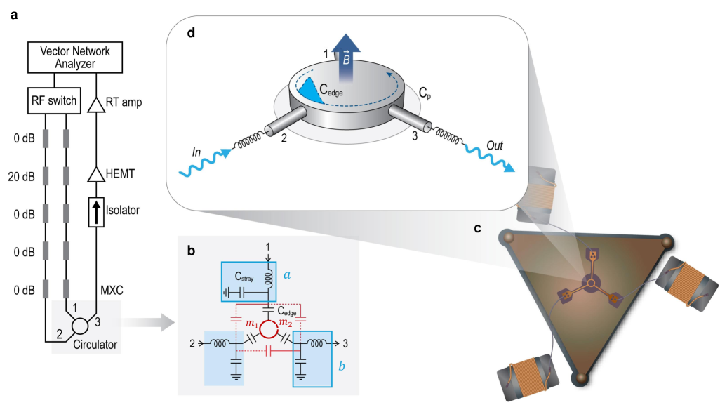
The configuration of our three-port circulator device is shown in the lower right corner of Fig. 1, and consists of an EMP resonator with a radius of 100 m and three lumped element inductors, each with an inductance nH. The inductor and the stray capacitor form an LC resonator, whose resonance frequency is set to closely match the EMP resonance frequency . At each port of the circulator, the EMP resonator is capacitively coupled to an LC resonator through an edge capacitor , which is formed between the Au pad and the EMP resonator (Fig. 1b). The microwave transmission coefficients and are characterized using a measurement scheme depicted in Fig. 1a and described in Appendices A and B. All measurements were performed at a temperature of approximately mK.
II.2 Circulator Characterization.
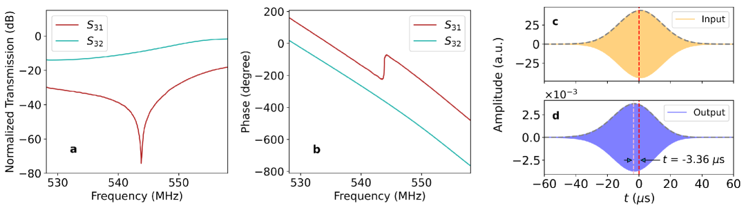
The primary result of this work is the non-reciprocal response of the device, including the transmission contrast and the phase shift when excited from different ports, thus producing circulation. Figures 2 a and b show forward transmission for the two paths and as a function of frequency. The response is clearly non-reciprocal in amplitude and phase . A particularly interesting response arises for MHz, where the amplitude difference between and exceeds dB, and undergoes an abrupt phase shift of approximately relative to (see Appendix C for details). This pronounced non-reciprocal transmission, accompanied by a corresponding -phase shift, indicates proximity to an exceptional point, where the coupling between the pair of LC resonators vanishes in one direction. [16, 17, 18].
A positive phase variation results in a negative group delay, expressed as . This characteristic can be utilized in devices such as temporal circulators or gyrators, which allow the separation of transmitter and receiver signals in the time domain through a directional -phase shift. Such non-reciprocal phase shifts are critical for applications requiring signal isolation and directional wave control. We demonstrate the effect of negative group delay by calculating the time-domain response to a simulated narrow-band incident pulse injected at port 1, with a center frequency of 543.8 MHz and a 50-Hz bandwidth, as shown in Fig. 2c. The output pulse leaving port 3 is computed by convolving the simulated incident pulse and the experimentally obtained transmission spectrum. Figure 2d shows the calculated output wave, where the peak of the envelope arrives approximately earlier than the incident wave, indicating a negative group delay. While positive group delays are common, negative group delays–often associated with superluminal effects–are rare and typically emerge in exotic physical systems[19, 20, 21, 22]. The port-dependent group delay, combined with the transmission amplitude demonstrated here, could be exploited in the development of novel on-chip components, such as isolators and circulators based on directional phase engineering. The underlying physical mechanism responsible for the observed negative group delay will be discussed in the Simulation section.
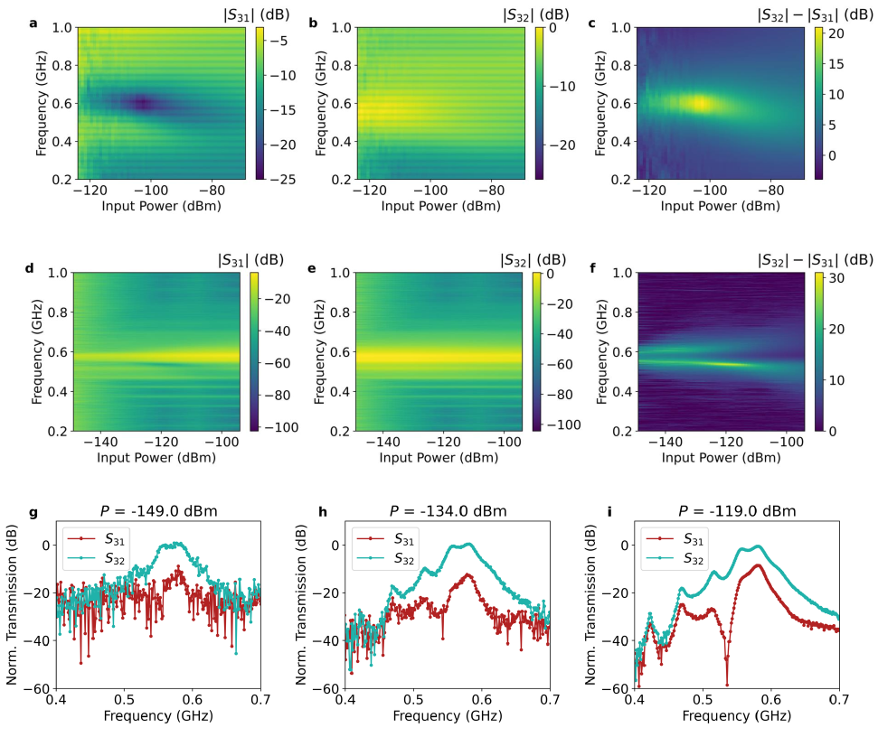
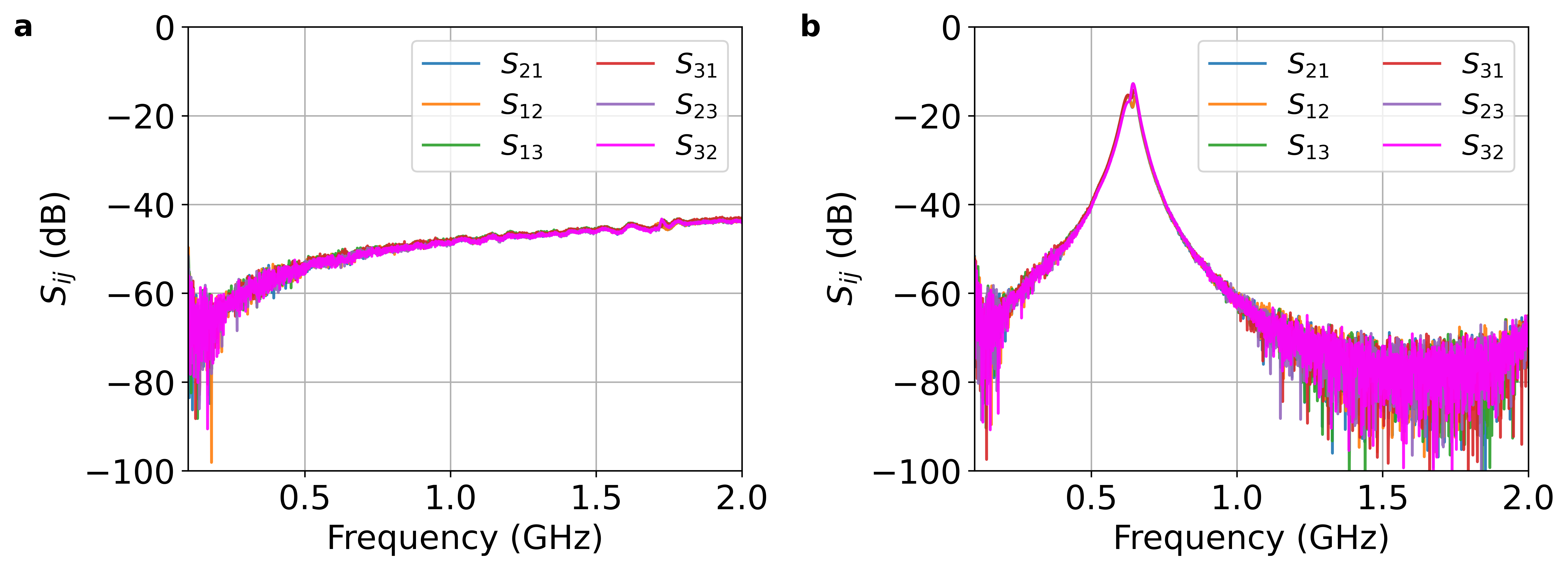
Next, we examine the transmission in an EMP resonator, both with and without LC resonators, across a wide spectral range. The transmission through the same EMP resonator, without coupling to an LC resonator, is shown in Figs. 3 a–c. Due to the constructive and destructive interference between the EMP mode and the port-to-port RF signal transmitted through the parasitic capacitance (Fig. 1), and exhibit a non-reciprocal response with a bandwidth of approximately 100 MHz. The isolation magnitude, , reaches a maximum of dB over a circulation intensity range of approximately dBm. Figures. 3 d–f show the transmission spectra as a function of frequency and input power when the EMP and LC resonators are coupled. For excitation from port 1, the magnitude of is smaller than dB if the input power is smaller than dBm. In contrast, for excitation from port 2, the magnitude of remains nearly unchanged over an input power range larger than dBm. The device exhibits non-reciprocity of 20 dB over the input intensity range from to dBm (Fig. 3f), which is relevant for several applications, including superconducting quantum information science[23] and dark-matter axion searches [24].
The spectral response at varying input power levels is presented in greater detail in Figs. 3 g–i. At an input power of dBm at the circulator’s port, exhibits a Lorentzian-like resonance with the quality factor , while shows a subtle resonance peak (Fig. 3g). Compared to the EMP circulator without coupling to an LC resonator, the LC-resonator-coupled configuration achieves significantly higher transmission, with an insertion loss of approximately dB at the transmission peak (see Appendix D). This enhancement can be attributed to the impedance matching between the port impedance and the impedance of the QAH edge state. Transmission can be enhanced to near-unity levels through optimized impedance matching and improved circuit fabrication.
The broadband non-reciprocal response in the 450–650 MHz frequency range of the LC-resonator-coupled EMP circulator arises from the interference between phase-sensitive plasmonic and parasitic capacitance pathways. For the shorter edge path (port 2 to 3), two LC resonators are capacitively coupled to the EMP resonator, leading to constructive interference with the parasitic transmission. In contrast, for the longer edge path (port 1 to 3), the same coupling occurs; however, the increased path length induces an out-of-phase interaction with the parasitic transmission. This phase mismatch results in destructive interference between the plasmonic and parasitic paths, thereby reducing overall transmission. As the input intensity increases, a transmission dip gradually emerges, reaching a minimum at dBm (Figs. 3 h and i). In addition to the broad-band transmission reduction from port 1 to 3, this dip provides exceptionally high isolation, exceeding dB within a bandwidth of approximately MHz.
II.3 Simulation
We now turn to understanding the origin of the sharp transmission dip and the associated negative group delay. This behavior stems from the non-reciprocal interaction between a pair of LC resonators and a chiral EMP resonator. The system is modeled by a minimal non-Hermitian Hamiltonian, assuming ideal non-reciprocity [25, 26, 15]:
| (1) |
where and are the decay rates of the input and output LC resonators, respectively. and are the decay rates of the EMP resonators along different propagation paths, as illustrated in Fig. 1b. is the frequency detuning of the electromagnetic field with respect to the LC and EMP resonance at frequency and , respectively. denotes the coupling strength between the resonators. Given the almost identical resonance frequencies of the input and output LC resonators (Fig. 5b), we set and . In the EMP resonator, asymmetric coupling emerges due to its chiral nature, leading to differences in propagation time and loss for the and modes depending on the path length and input microwave power. By applying coupled mode theory, the transmission can be expressed as:
| (2) |
where characterizes the LC resonator and characterizes the EMP resonator. Given that the path length of mode is approximately twice that of , we set and near the exceptional point.
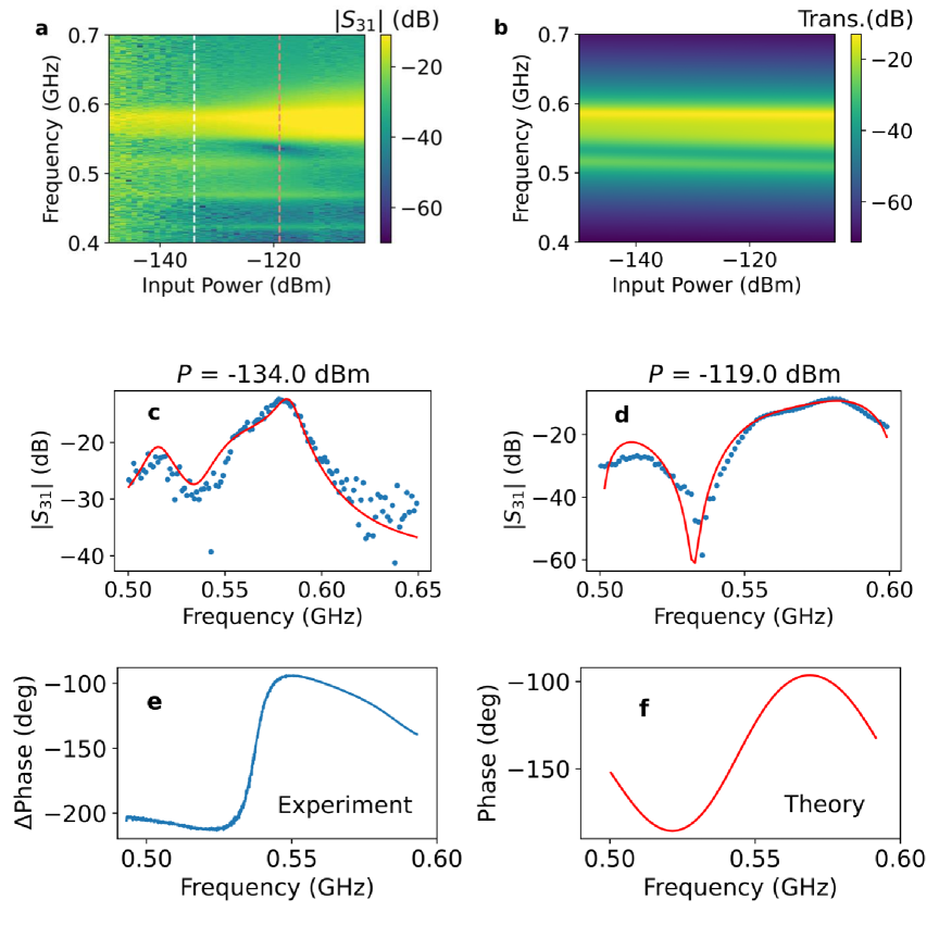
We find that the measured transmission spectra are qualitatively in agreement with the theoretical model, indicating that the circulation mechanism is governed by asymmetric coupling between the LC resonator and the EMP mode (Figs. 4 a and b). At low excitation power, the measured transmission closely matches the model, with fitted parameters: MHz, MHz, and MHz (Fig. 4 c). As the input power increases, the fitted coupling strength rises to MHz, while and increase to and MHz, respectively, at the point of maximum isolation (Fig. 4 d).
This simple model also captures the phase behavior observed in the experimental data, especially near the exceptional point, as shown in Figs. 4 e and f. In this case, the phase response of is corrected by subtracting the phase of to eliminate the line phase shift, allowing for a direct comparison with the theoretical result. The residual mismatch between experiment and theory at higher power is attributed to the power-dependent plasmon damping and coupling effects that lie outside the minimal model.
III Conclusion
In this work, we demonstrated a novel circulation mechanism in a topological circulator comprising a QAH edge magnetoplasmonic resonator coupled to LC resonators. Within an input power range of to dBm, the circulator maintains a relatively stable bandwidth and passband center frequency, indicating robust performance under low-power conditions. This power independence suggests the device is well-suited for integration into superconducting quantum information science platforms and high-energy physics experiments. If fully harnessed, this mechanism could facilitate the realization of a topological circulator with near-unitary forward transmission and exceptionally high isolation in the reverse direction. In conclusion, our results highlight the significant potential of Chiral plasmons to provide enhanced control over signal transmission and isolation across a wide dynamic range.
Acknowledgements.
We would like to thank Yaniv Rosen, Kristin Beck, and Enrico Rossi for helpful discussions. This work was performed under the auspices of the US Department of Energy by Lawrence Livermore National Laboratory under Contract No. DE-AC52-07NA27344. The project was supported by the Laboratory Directed Research and Development (LDRD) programs of LLNL (21-ERD-014) and HEP Laboratory Detector Research and Development program. The authors also acknowledge support from NSF Convergence Accelerator program under Grant 2040737.Appendix A Experimental configuration and device fabrication
The transmission of the circulator is probed by measuring the transmission parameters for various powers. The experimental configuration is summarized in Fig. 1. The measurements were performed on two ports of the circulator with an RF switch located at room temperature. The input microwave signals transmit through coax cables with a dB attenuator at room temperature (not shown in Fig. 1a) and a dB attenuator at K. The total attenuation from the vector network analyzer down to the sample is about dB. The power values expressed in decibels in this letter represent the estimated power at the input port of the circulator. The circulator output goes through a cryogenic isolator at the still stage and is amplified by a HEMT amplifier (LNF-LNC0.3-14A, Low Noise Factory) with a noise temperature of K at the 4 K stage. At room temperature, the transmission signal is further amplified by a low-noise room temperature amplifier with a total gain of dB (ZX60-4016E-S+, Mini-Circuits).
The 6 quintuple layers of Cr0.12(Bi0.26Sb0.62)2Te3 thin films were grown using ultrahigh vacuum molecular beam epitaxy. Epi-ready semi-insulating ( cm) GaAs (111) B substrates were pre-annealed in the chamber at up to under Te-rich environment. During the co-evaporated growth, high-purity Bi (), Te (), Cr () were evaporated from Knudsen effusion cells while Sb () was evaporated from a cracker cell. Upon material growth, the circulator devices were fabricated via standard photolithography. The mesa disk was first patterned by photolithography and then etched by CF4/Ar using reactive ion etching. The coplanar waveguides and ground planes were patterned by photolithography, and nm of Ti and nm of Au were deposited using electron beam deposition, followed by a liftoff process.
Appendix B Room temperature device characterization
The circulator sample was initially characterized without a matching inductor and its impedance was expected to be on the order of the Hall resistance, k. Since the impedance of the measurement circuit was 50 , the lack of a matching circuit at the input results in a power reflection of approximately at the input port of the circulator. As a control, we first measured all microwave parameters before mounting the inductors, observing that all ports are equivalent with a transmission magnitude approximately dB at MHz, as shown in Fig. 5b.
We then implemented a matching network at the input ports of the circulator by utilizing lumped element nH inductors in series (Fig. 1). The inductors coupled with the effective capacitance of the circuit serve as an impedance matching network for the coaxial lines and the high impedance of the circulator (Fig. 1b). Physically, the matching process utilizes the resonance created by the inductors and the effective stray capacitance of the circuit. The resonance is made coincident with the circulator edge magnetoplasmonic resonance frequency, effectively increasing the energy coupled into the circulator. Increasing the energy coupled into the circuit increases the signal-to-noise ratio. In practice, better coupling improves the insertion loss associated with reflections arising from impedance mismatch. The appropriate inductor value was determined by testing different inductors on a similar sample and collecting transmission measurements at room temperature. Figure 5b shows the six-way transmission spectra, which illustrate reciprocal transport with an resonant frequency of MHz, an amplification magnitude of dB, and a quality factor of .
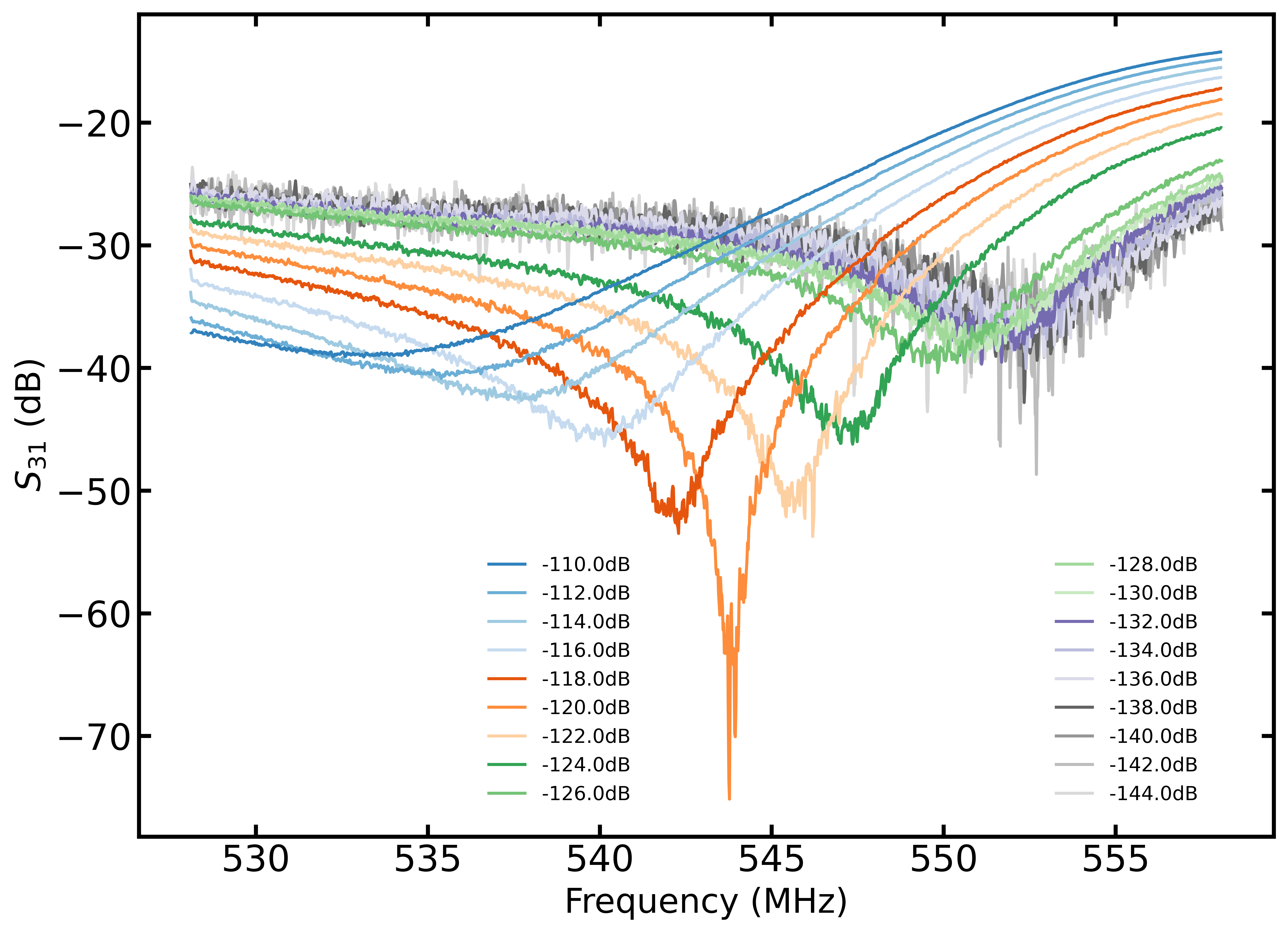
Appendix C Power dependent transmission measurements for
Figure 6 shows the magnitude plotted for various powers, uncovering interesting non-linear features which hint at the underlying physics of the anomalous Hall circulator. Signal incoming on the port 1 exhibits a power-dependent shift in both frequency and bandwidth, while transmission excited from port 2 does not exhibit a power dependence. The observed power dependence of the dip frequency can be directly attributed to the dynamics of the topological state. At sufficiently low powers, i.e., below dBm, the topological edge state is separated from the bulk state and dissipationless chiral edge magnetoplasmon currents excite plasmonic modes, . As the power increases, microwave photon-induced hopping occurs in the charge puddles of the bulk, which is capacitively coupled to the edge states, and dissipation begins to set in. At sufficiently high powers, the shift in frequency can be associated with an enhanced edge capacitance of the QAH material. This aligns with prior experimental findings in circulators utilizing anomalous Hall materials.
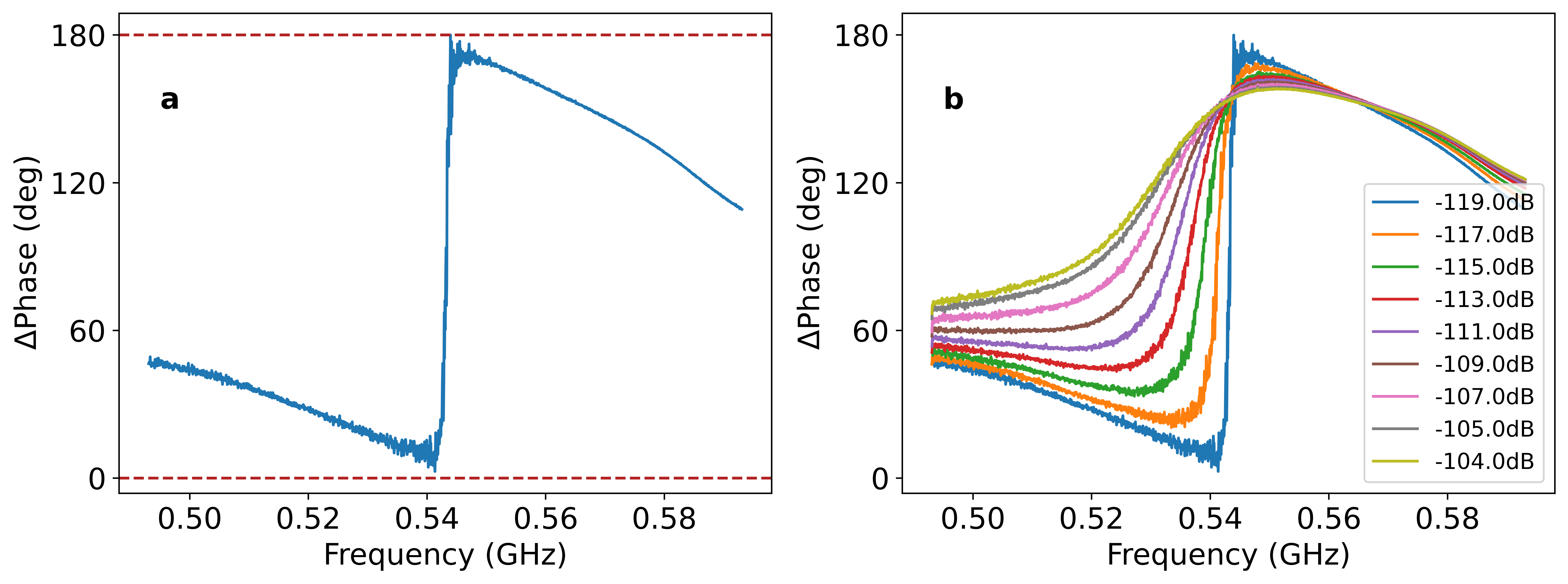
The phase difference between and at different excitation powers is illustrated in Fig. 7. At the maximum transmission dip ( dBm), a -phase shift is observed (Fig. 7a). The slope of phase change decreases when exceeds dBm (Fig. 7b).
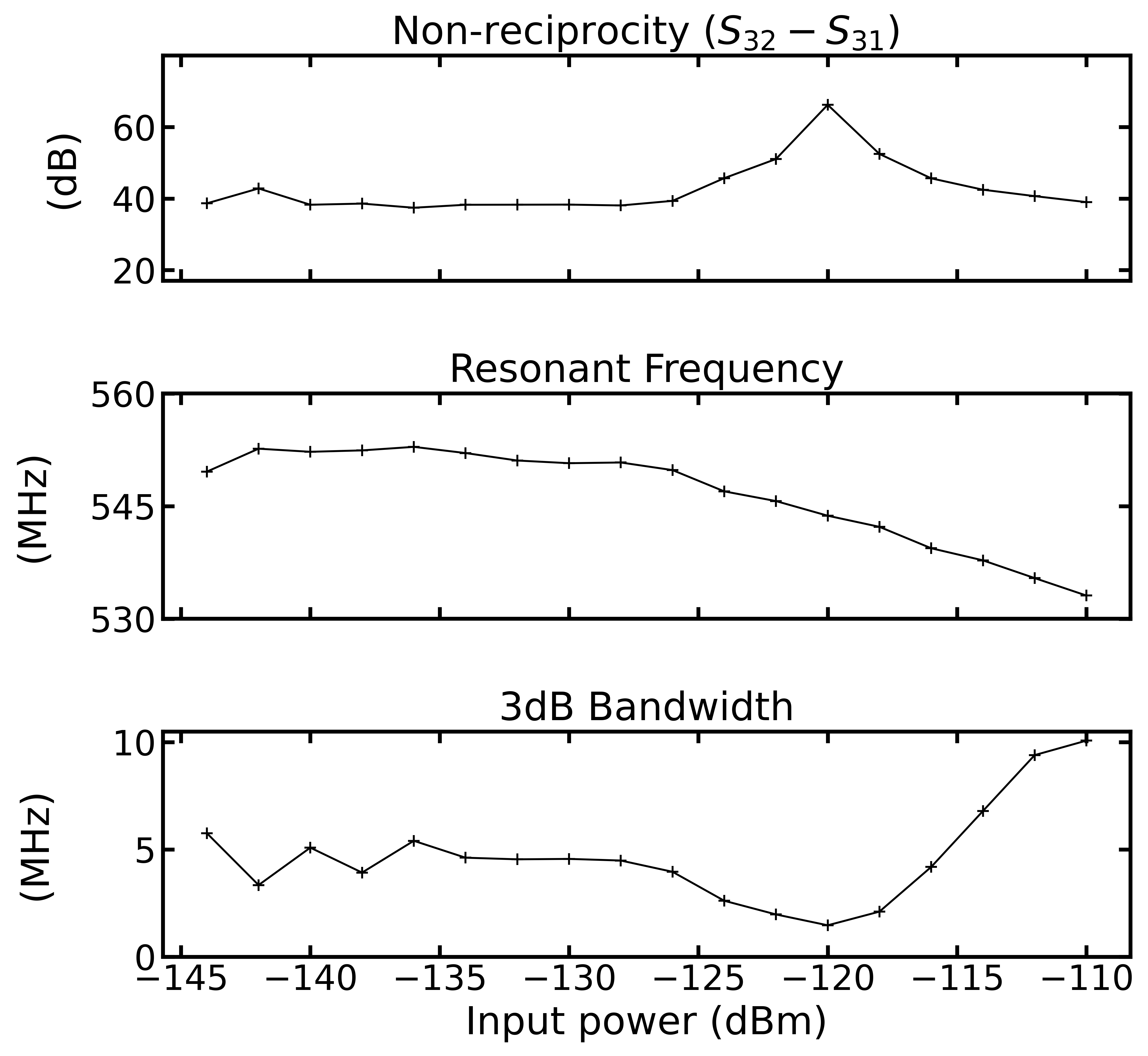
Figure 8 shows the non-reciprocity , resonant frequency shift, and the dB bandwidth as a function of input power. Note, for input powers in the range of to dBm the circulator’s bandwidth and passband center frequency are relatively power independent suggesting the circulator can exhibit a stable regime in power ranges that are relevant to superconducting quantum information science platforms and high-energy physics experiments.
Appendix D Insertion loss characterization
The insertion loss of the circulator was measured in a different Bluefors dilution refrigerator after the sample had been stored for more than two years at ambient temperature in a low-vacuum desiccator. The characterization diagram is shown in Fig 9. The circulator was cooled to below mK. A network analyzer was used to perform transmission measurements through the system. To determine the insertion loss of the circulator, a transmission measurement was made through the transmission port () and the proportion of power transmitted through the receiver was measured at the output (). Two cryogenic switches (Radial R585433210) enabled swapping between the circulator ports and a short cable. In addition, a second transmission line () was used to measure the isolation of the circulator. On the output line (), the signal was amplified by a HEMT amplifier mounted to the 4 K stage, followed by a room temperature amplifier. An isolator before the HEMT amplifier was used to reduce standing waves within the receiver. Broadband transmission measurements were made of both the and of the circulator. At cryogenic temperatures, there is a dB difference in transmission between input lines and .
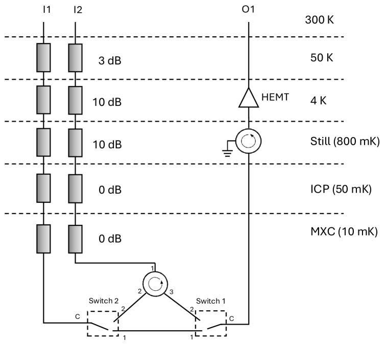
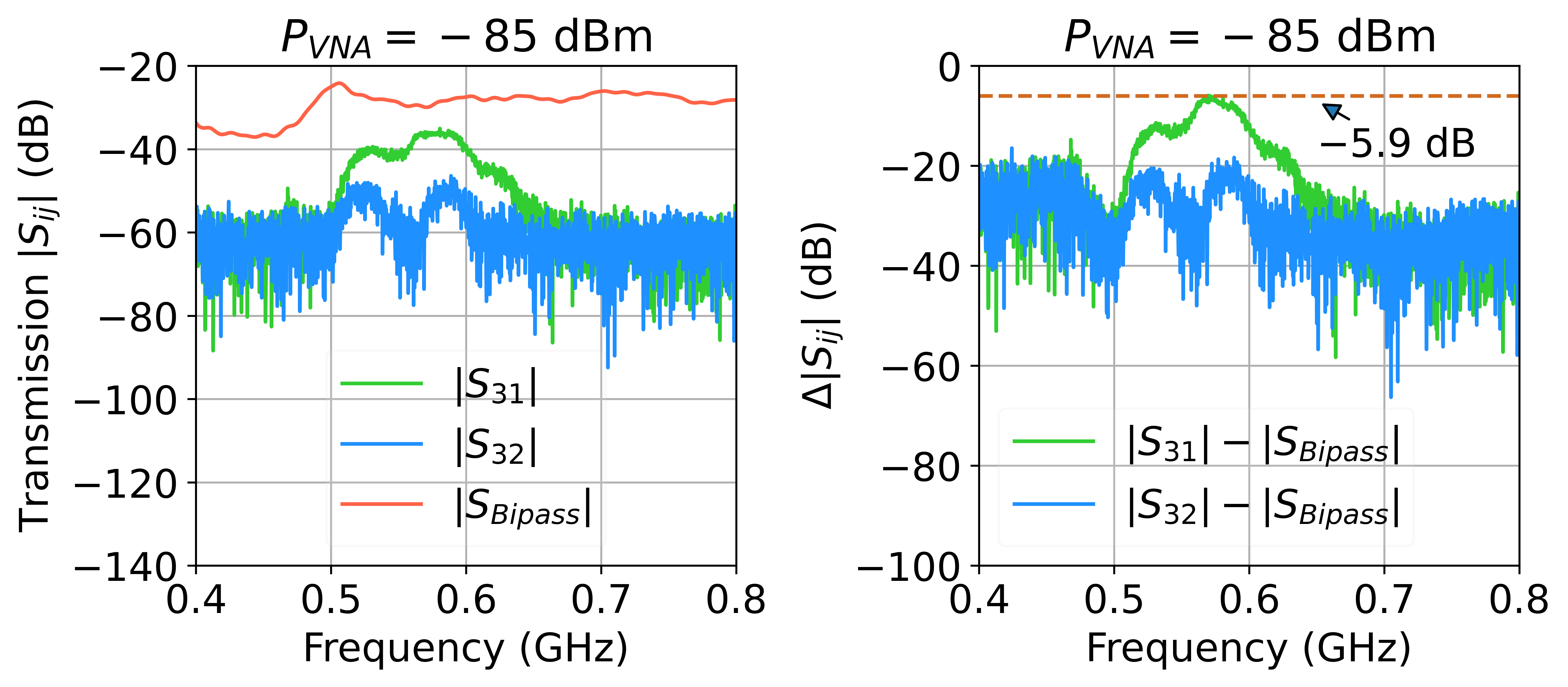
To determine the insertion loss of the circulator, transmission measurements were performed with the circulator both in the receiver circuit and bypassed, while applying a range of input powers. Any additional transmission losses observed when the circulator was switched in were attributed to its insertion loss. As shown in Fig. 10, the insertion loss of the circulator was found to be approximately dB with an isolation of dB in the low power regime.
References
- Mahoney et al. [2017a] A. C. Mahoney, J. I. Colless, S. J. Pauka, J. M. Hornibrook, J. D. Watson, G. C. Gardner, M. J. Manfra, A. C. Doherty, and D. J. Reilly, On-chip microwave quantum hall circulator, Phys. Rev. X 7, 011007 (2017a).
- Mahoney et al. [2017b] A. C. Mahoney, J. I. Colless, L. Peeters, S. J. Pauka, E. J. Fox, X. Kou, L. Pan, K. L. Wang, D. Goldhaber-Gordon, and D. J. Reilly, Zero-field edge plasmons in a magnetic topological insulator, Nature Communications 8, 1836 (2017b).
- Martinez et al. [2024] L. A. Martinez, G. Qiu, P. Deng, P. Zhang, K. G. Ray, L. Tai, M.-T. Wei, H. He, K. L. Wang, J. L. DuBois, and D.-X. Qu, Edge magnetoplasmon dispersion and time-resolved plasmon transport in a quantum anomalous hall insulator, Phys. Rev. Res. 6, 013081 (2024).
- Ashoori et al. [1992] R. C. Ashoori, H. L. Stormer, L. N. Pfeiffer, K. W. Baldwin, and K. West, Edge magnetoplasmons in the time domain, Phys. Rev. B 45, 3894 (1992).
- Kumada et al. [2011] N. Kumada, H. Kamata, and T. Fujisawa, Edge magnetoplasmon transport in gated and ungated quantum hall systems, Phys. Rev. B 84, 045314 (2011).
- Kumada et al. [2014] N. Kumada, P. Roulleau, B. Roche, M. Hashisaka, H. Hibino, I. Petkovic, and D. C. Glattli, Resonant edge magnetoplasmons and their decay in graphene, Phys. Rev. Lett. 113, 266601 (2014).
- Bosco and DiVincenzo [2019] S. Bosco and D. P. DiVincenzo, Transmission lines and resonators based on quantum hall plasmonics: Electromagnetic field, attenuation, and coupling to qubits, Phys. Rev. B 100, 035416 (2019).
- Devoret et al. [2007] M. Devoret, S. Girvin, and R. Schoelkopf, Circuit-qed: How strong can the coupling between a josephson junction atom and a transmission line resonator be?, Annalen der Physik 519, 767 (2007).
- Bosco et al. [2019] S. Bosco, D. DiVincenzo, and D. Reilly, Transmission lines and metamaterials based on quantum hall plasmonics, Phys. Rev. Appl. 12, 014030 (2019).
- Lin et al. [2024] C. Lin, K. Futamata, T. Akiho, K. Muraki, and T. Fujisawa, Resonant plasmon-assisted tunneling in a double quantum dot coupled to a quantum hall plasmon resonator, Phys. Rev. Lett. 133, 036301 (2024).
- Chang et al. [2013] C.-Z. Chang, J. Zhang, X. Feng, J. Shen, Z. Zhang, M. Guo, K. Li, Y. Ou, P. Wei, L.-L. Wang, Z.-Q. Ji, Y. Feng, S. Ji, X. Chen, J. Jia, X. Dai, Z. Fang, S.-C. Zhang, K. He, Y. Wang, L. Lu, X.-C. Ma, and Q.-K. Xue, Experimental observation of the quantum anomalous hall effect in a magnetic topological insulator, Science 340, 167 (2013).
- Chang et al. [2023] C.-Z. Chang, C.-X. Liu, and A. H. MacDonald, Colloquium: Quantum anomalous hall effect, Rev. Mod. Phys. 95, 011002 (2023).
- Hatano and Nelson [1996] N. Hatano and D. R. Nelson, Localization transitions in non-hermitian quantum mechanics, Phys. Rev. Lett. 77, 570 (1996).
- Hatano and Nelson [1998] N. Hatano and D. R. Nelson, Non-hermitian delocalization and eigenfunctions, Phys. Rev. B 58, 8384 (1998).
- Orsel et al. [2024] O. E. Orsel, J. Noh, P. Zhu, J. Yim, T. L. Hughes, R. Thomale, and G. Bahl, Giant non-reciprocity and gyration through modulation-induced hatano-nelson coupling in integrated photonics (2024), arXiv:2410.10079 [physics.optics] .
- Miri and Alù [2019] M.-A. Miri and A. Alù, Exceptional points in optics and photonics, Science 363, eaar7709 (2019).
- Li et al. [2023] A. Li, H. Wei, M. Cotrufo, W. Chen, S. Mann, X. Ni, B. Xu, J. Chen, J. Wang, S. Fan, C.-W. Qiu, A. Alù, and L. Chen, Exceptional points and non-hermitian photonics at the nanoscale, Nature nanotechnology 18, 706 (2023).
- Klauck et al. [2025] F. U. J. Klauck, M. Heinrich, A. Szameit, and T. A. W. Wolterink, Crossing exceptional points in non-hermitian quantum systems, Science Advances 11, 8275 (2025).
- Low et al. [2018] T. Low, P.-Y. Chen, and D. N. Basov, Superluminal plasmons with resonant gain in population inverted bilayer graphene, Physical Review B 98, 041403 (2018).
- Wang et al. [2000] L. J. Wang, A. Kuzmich, and A. Dogariu, Gain-assisted superluminal light propagation, Nature 406, 277 (2000).
- Safavi-Naeini et al. [2011] A. H. Safavi-Naeini, T. P. M. Alegre, J. Chan, M. Eichenfield, M. Winger, Q. Lin, J. T. Hill, D. E. Chang, and O. Painter, Electromagnetically induced transparency and slow light with optomechanics, Nature (London) 472, 69 (2011).
- Xiao et al. [2021] J.-K. Xiao, Q.-F. Wang, and J.-G. Ma, Negative group delay circuits and applications: Feedforward amplifiers, phased-array antennas, constant phase shifters, non-foster elements, interconnection equalization, and power dividers, IEEE Microwave Magazine 22, 16 (2021).
- Mallet et al. [2009] F. Mallet, F. R. Ong, A. Palacios-Laloy, F. Nguyen, P. Bertet, D. Vion, and D. Estève, Single-shot qubit readout in circuit quantum electrodynamics, Nature Physics 5, 791 (2009).
- Bartram et al. [2021] C. Bartram et al. (ADMX Collaboration), Axion dark matter experiment: Run 1b analysis details, Phys. Rev. D 103, 032002 (2021).
- Lau and Clerk [2018] H. K. Lau and A. A. Clerk, Fundamental limits and non-reciprocal approaches in non-hermitian quantum sensing, Nat. Commun. 9, 4320 (2018).
- Wang et al. [2021] Y.-Y. Wang, S. van Geldern, T. Connolly, Y.-X. Wang, A. Shilcusky, A. McDonald, A. A. Clerk, and C. Wang, Low-loss ferrite circulator as a tunable chiral quantum system, Phys. Rev. Appl. 16, 064066 (2021).