Energy-Efficient UAV Replacement in Software-Defined UAV Networks
Abstract
Unmanned Aerial Vehicles (UAVs) in networked environments face significant challenges due to energy constraints and limited battery life, which necessitate periodic replacements to maintain continuous operation. Efficiently managing the handover of data flows during these replacements is crucial to avoid disruptions in communication and to optimize energy consumption. This paper addresses the complex issue of energy-efficient UAV replacement in software-defined UAV network. We introduce a novel approach based on establishing a strict total ordering relation for UAVs and data flows, allowing us to formulate the problem as an integer linear program. By utilizing the Gurobi solver, we obtain optimal handover schedules for the tested problem instances. Additionally, we propose a heuristic algorithm that significantly reduces computational complexity while maintaining near-optimal performance. Through comprehensive simulations, we demonstrate that our heuristic offers practical and scalable solution, ensuring energy-efficient UAV replacement while minimizing network disruptions. Our results suggest that the proposed approach can enhance UAV battery life and improve overall network reliability in real-world applications.
Index Terms:
Software-defined UAV network, energy-efficient UAV replacement, strict total ordering relation, integer linear program, Gurobi solverI introduction
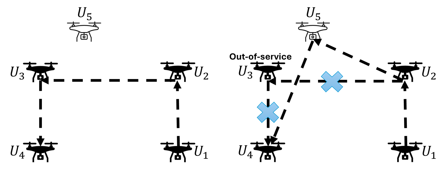
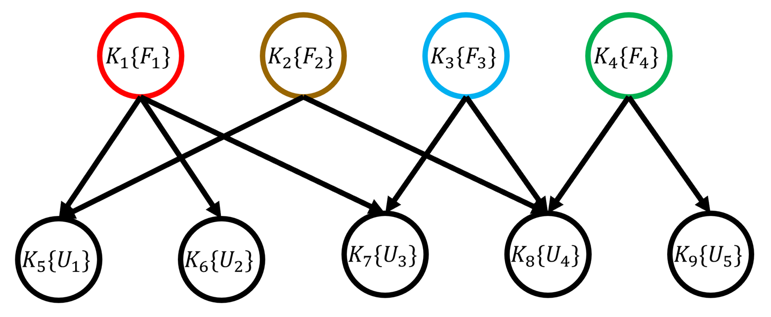
Unmanned Aerial Vehicles (UAVs) demonstrate remarkable capabilities, including clear line-of-sight (LOS) ground node connectivity, rapid deployment, and adaptability, rendering them indispensable in a wide range of applications, including surveillance, search and rescue missions, delivery services, and communication networks. During a long mission, UAVs may periodically go out of service as they go out of power or develop faults [1]. Their communication interfaces may also be shut down to conserve power, or one or more of the UAVs may be withdrawn, when less dense network is required. In all these cases the network needs to re-configure and the ongoing voice, video or data sessions are required to be handed over to one of the working UAVs according to some predefined criteria [2]. Handover allows for continuity of network communication with only a minor increase of message latency during the handover process [3]. Fig. 1 illustrates an example of a handover process. In this scenario, UAV runs out of power and must go out of service, requiring replacement by a new UAV, , to extend the operational duration of network. Since the data flow currently passes through UAV , it must be handed over to the new path .
I-A Related work
In the existing literature, researchers in [4]-[11] have explored the concept of UAV replacement. Notably, [4] and [5] have introduced a battery replacement system where UAV batteries are swapped at charging stations after landing, allowing them to resume communication services. However, this method introduces coverage gaps in the communication service area and falls short in ensuring uninterrupted communication for ground users. In contrast, [6] proposed a scheduling algorithm to manage multiple UAV replacements, enabling long-term communication services, particularly during hotspot events, extending for several hours. Meanwhile, [7] introduced a model that involves swapping the positions of UAVs with depleted batteries with those of neighboring UAVs possessing higher remaining battery life. In [8], researchers investigated the issue of link outage during UAV replacements and formulated strategies to ensure outage-free replacements. In a different approach, [9] focused on the UAV charging mechanism by establishing multiple battery charging stations in the field, minimizing UAV energy consumption. However, that work did not prioritize meeting the communication service performance requirements of ground users or ensuring adequate data rates for each user. In [10] and [11], the authors presented a framework that addresses the challenge of maintaining uninterrupted coverage in a UAV-assisted wireless communication system, particularly when the currently operating UAV depletes its energy reserves. In such scenarios, service continuity is ensured by substituting the exhausted UAV with a fully charged one. The primary goal of this replacement process is to maximize the total data rate attainable for all ground users. This objective is realized through the collaborative optimization of three-dimensional multi-UAV trajectories and resource allocation to individual users by the UAVs.
I-B Motivation
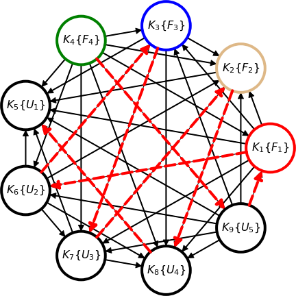
The benefits of UAV networks come with significant challenges, especially when UAVs need to be taken out of service for reasons such as battery depletion, hardware malfunctions, or mission completion. In dense UAV networks, like the one depicted in Fig. 2, UAVs are often responsible for maintaining important communication flows between multiple devices. When UAVs are scheduled to be replaced, the handover of communication flows passing through them must be carefully managed. Inefficient handovers can lead to increased energy consumption, as UAVs must hover for extended periods. This not only shortens the operational lifetime of the network but also negatively impacts mission objectives and service continuity.
The problem of minimizing the hovering energy consumption during the handover process is therefore crucial. Optimizing this process can extend the overall operational time of UAV networks, reduce operational costs, and improve the sustainability of these systems, especially in energy-constrained scenarios. Furthermore, energy-efficient UAV replacement is of particular importance in emergency response scenarios where prolonged aerial operation is essential for search-and-rescue missions or real-time data collection, and interruptions in service can have life-threatening consequences.
In addition to emergency response, other potential applications of energy-efficient UAV replacement include logistics and delivery systems, aerial surveillance for smart cities, and remote sensing operations in agriculture. These applications rely on the continuous and reliable operation of UAV networks over long periods, which makes the efficient replacement of UAVs a high-priority research problem.
I-C Contribution
In this paper, we examine how to replace UAVs efficiently in software-defined UAV networks while conserving energy. To the best of our knowledge, this problem has not been explored previously. To this end, we introduce a novel approach that centers around the establishment of a strict total ordering relation for UAVs and data flows. This approach enables us to formulate the problem as an integer linear program and leverage advanced tools such as the Gurobi solver to identify optimal handover schedules. Additionally, we propose a heuristic algorithm designed to significantly reduce computational complexity while maintaining efficiency.
II Problem Statement
In this paper, we analyze software-defined UAV networks that consist of a single SDN controller. The SDN paradigm is captivating as it injects flexibility and programmability into networks. SDN is a pivotal technology in the realization of 5G [12]. It enables the operation and validation of networks in a more adaptable manner than traditional networks, allowing for the efficient implementation of customized services tailored to 5G networks [13]. In the context of SDN, the controller is responsible for calculating configurations and transmitting forwarding rules to the corresponding switch. It is crucial that configuration updates are executed consistently and swiftly to prevent congestion, delays, and policy violations [14], [15]. A flow corresponds to a path created from a source node to a destination node in order to transmit traffic.
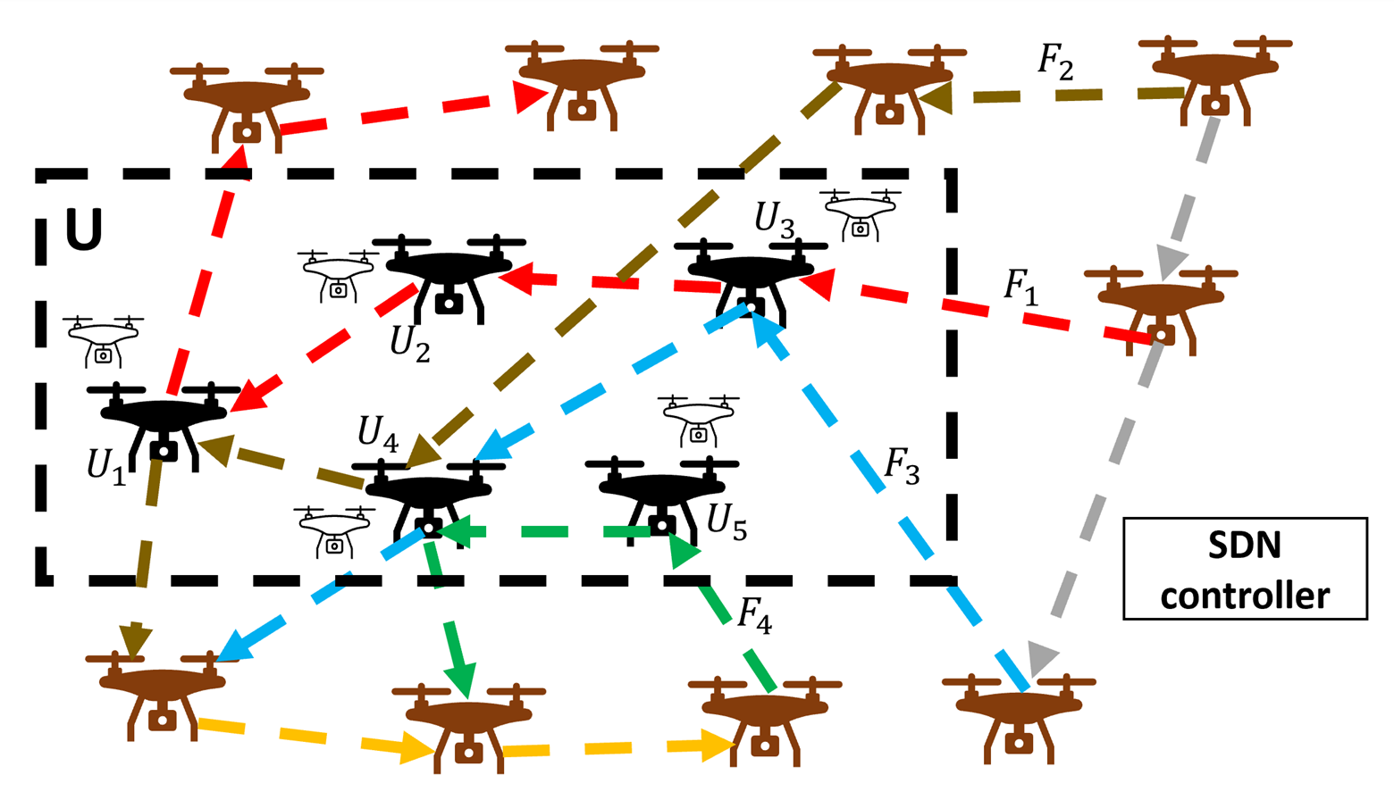
Let us consider a sample software-defined UAV network with UAVs and flows as given in Fig. 2. We show the set of UAVs that need to go out of service with . Moreover, the set of flows that pass through at least one of the members of set is shown with . Although not all communication links between UAVs are shown in Fig. 2, any flow from UAV to UAV indicates the presence of a communication link between them. Additionally, multiple flows can share the same link; however, this scenario is not depicted in Fig. 2 to enhance the visual clarity of different flow routes. We also point out that the new UAVs, taking the place of the old ones, are displayed in white. For the sample network in Fig. 2, we have , , , and . Let , , and be the number of deleted, inserted, and modified rules required for the handover of flow . Moreover, we show the deletion, insertion, and modification time of each rule by , , and , respectively. According to the test result in [16], the delay of deleting and inserting is 5 ms, while the delay of modifying is set to 10 ms. Therefore, the required time for handover of flow (updating the control commands by the SDN controller) can be written as . For the handover scenario illustrated in Fig. 1, the forwarding rule must be modified to , the rule needs to be deleted, and a new forwarding rule must be created. As a result, we have . Consequently, the total time required for the handover is given by ms.
The primary focus of this study is to determine a handover schedule that minimizes the hovering energy consumption during the UAV replacement process. To see the effect of handover ordering on the energy efficiency, two different handover schedules for the sample network in Fig. 2 are schematically depicted in Fig. 5. The required time for handover of flow is shown with for . This figure shows the UAVs that go out of service at each time. We highlight that a UAV is considered out of service when all the flows passing through it are successfully handed over. For the handover ordering in schedule 1, UAVs and go out of service at time . Next, UAV goes out of service at . Finally, UAVs and stop operating at . Hence, assuming that the hovering power of all UAVs is , the hovering energy required for the first schedule is . In a similar way, we can show that the hovering energy consumption of the second schedule is . It is not hard to see that the handover times for the flows are ms, ms, ms, and ms. Therefore, for the special case of W, we have J and J, which shows that the first schedule achieves less hovering energy consumption compared to the second one. The central question now arises: how can one identify the optimal handover schedule with the least total hovering energy consumption?
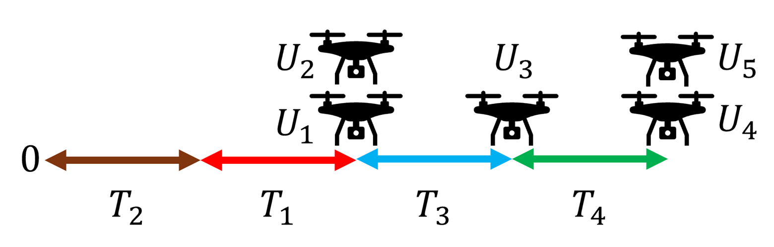
(a) schedule 1: , , , and
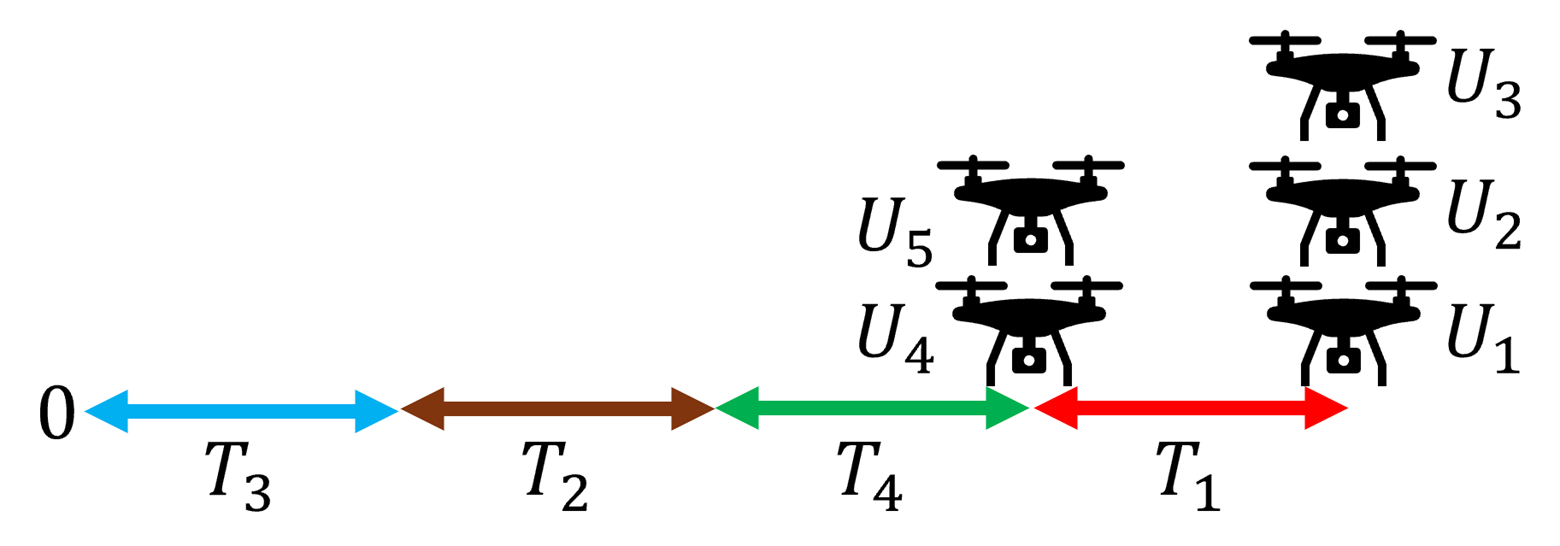
(b) schedule 2: , , , and
III Problem Formulation
In this section, we introduce a systematic method that hinges on the establishment of a strict total ordering relation for UAVs and data flows. The objective is to address the problem of minimizing the total hovering energy consumption during the UAV replacement in a software-defined UAV network. We begin by providing some preliminary definitions that are necessary in formulating the problem [17].
Definition 1.
A relation on the set is defined as
The relation can alternatively be shown by a directed graph in which is the set of vertices and there is a directed edge from node to node if and only if .
Definition 2.
A relation on the set is called a strict total ordering relation if the following properties hold
-
•
is irreflexive: for every .
-
•
Any two members of are comparable: or .
-
•
is asymmetric: implies that .
-
•
is transitive: and imply that .
A strict total ordering relation imposes a strict hierarchy on the elements of a set, ensuring that no two distinct elements are considered equal. It is not hard to see that the corresponding graph of a strict total ordering relation is a complete directed graph in which there is only one directed edge between any two nodes in the graph. Moreover, the longest path in the graph induces a valid ordering for the set of nodes.
To simplify the notation in our formulation, we map the combined set onto a new set, denoted as . Specifically, each is assigned to for , and each is assigned to for . This mapping is introduced because we aim to establish a strict total ordering for both UAVs and data flows. The combined set is thus essential and serves as a foundational component in the problem formulation.
Definition 3.
For a given handover problem instance (such as problem instance in Fig. 2), we define the dependency relation on the set in which if and only if flow passes through UAV .
Dependency relation demonstrates the fact that a UAV can go out of service as soon as all the flows passing through it have been handed over. Hence, the corresponding graph of a dependency relation is always bipartite. For an instance, the dependency graph of sample problem in Fig. 2 is depicted in Fig. 6. As it can be seen, there are directed edges from to , , and because the first flow () passes through the UAVs , , and .
In what follows, we formally present our approach to minimize the hovering energy consumption of UAVs that go out of service during the replacement process. Our method is based on finding a strict total ordering relation on the set for which . We point out that such relation induces an ordering for the set as well, which is indeed a handover schedule. Let .
To simplify the notation, we implicitly assume hereafter that tuples and sets have no multiplicity. Therefore, and denote a tuple and a set, respectively, with distinct elements. For formulating the problem, we define the binary indicator variable that takes the value if and , otherwise. Since , we conclude that for . Moreover, from the facts that any two members of are comparable and is asymmetric, we have for each . Additionally, transitivity of implies that for each . Finally, assuming that the hovering power of UAV is for , the total hovering energy consumption of UAVs that go out of service during the replacement process can be written as . Therefore, our goal problem can be formulated as the following integer linear program
| (1) |
As it can be seen, the complexity of the optimization problem (1) escalates notably as both and increase, resulting in a substantial increase in the number of binary variables and constraints. We emphasize that every viable solution to optimization problem (1) constitutes a strict total ordering relation on the combined set . Furthermore, the optimal solution to this problem establishes a hierarchy with the least total hovering energy consumption. As an illustration, Fig. 7 displays the optimal solution and induced hierarchy for the sample problem presented in Fig. 2. This solution is obtained by solving the optimization problem (1) with the Gurobi solver. As evident, the corresponding handover schedule is , , , and . Consequently, the optimal hovering energy consumption is given by . Substituting the values provided in Section II, we find J, which is lower than the hovering energy consumption of the schedules presented in Fig. 5.
IV Proposed Heuristic Algorithm
In this section, we present a heuristic algorithm designed for the optimization problem (1). For , let represent the set of UAVs in that are traversed by flow . Additionally, we define as the set of flows passing through the -th UAV, where .
Furthermore, we introduce , which denotes the total processing time of all flows within . Essentially, represents the time required for the replacement of the -th UAV.
With these definitions established, we can now define a score for each flow , which will be instrumental in formulating our proposed heuristic algorithm.
Definition 4.
The score of the -th flow is defined as
We point out that the unit of defined score is . Noting Definition 4, one can expect that a flow with high score is passing through the UAVs with high hovering powers which require less time for the replacement. As a result, those flows with high scores are good candidates to be handed over first to save the hovering energy consumption of UAVs. The formal description of proposed heuristic algorithm is given in Algorithm 1. In Algorithm 1, we initially calculate score values for all flows, and subsequently, these values are arranged in descending order to establish the handover sequence.
Proposition 1.
Algorithm 1 has a time complexity of .
Proof.
We determine the overall time complexity by evaluating the time complexity of each individual step. Considering the structure of Algorithm 1, we can conclude that calculating the values of for in the first step has a time complexity of . In the second step, computing the values of for has a time complexity of . Finally, sorting the values in the third step has a time complexity of . Therefore, the overall time complexity of Algorithm 1 is .∎
As an illustration, we addressed the sample problem presented in Fig. 2 using Algorithm 1. Consequently, the resulting handover schedule is , , , and . It is evident that the corresponding hovering energy consumption for this schedule is . Upon substituting the values provided in Section II, we find J, only J more than .
V Numerical Results
This section demonstrates the numerical results. To implement the suggested heuristic algorithms, Python 3.8.5 was employed. Additionally, for the optimization problem (1), we utilized the Gurobi solver to obtain the optimal solution.
V-A Simulation Setup
For the simulation, we considered a software-defined UAV network with one SDN controller and UAVs which were randomly distributed in a square area of m m. Since UAVs hover at high altitude, they maintain LOS channel between each other [18]. Hence, the path loss between the -th and the -th UAVs can be expressed as , where is the carrier frequency, is the light speed, and is the distance between the -th and the -th UAVs [19]. Therefore, the SNR in dB between the -th and the -th UAVs can be written as , where is the transmit power of the -th UAV, which is maintained fixed for all the UAVs, and is the additive white Gaussian noise variance. We assume that the -th UAV and the -th UAV have a successful link provided that , where is the minimum SNR threshold for the communication link between the UAVs [20]. The hovering power of the -th UAV can be expressed by , where is the mass of the ’th UAV, is the gravitational acceleration of the earth, is propellers’ radius, is the number of propellers, and is the air density [21]. In this simulation, we assume that is randomly chosen from the set kg. The total number of flows () was set to and . Furthermore, we made the assumption that a portion ranging from 12.5% to 25% (specifically, when takes on values in the set ) of the UAVs must be taken out of service and substituted with new ones. The values of the simulation parameters not explicitly mentioned here are the same as those used in [20] and [21].
V-B Performance Evaluation
To generate data flows, we randomly select two distinct UAVs and establish a route based on the shortest path between them. Since deriving a closed-form expression for the true expected value of hovering energy consumption is infeasible, we employ Markov Chain Monte Carlo (MCMC) simulations to approximate this expectation. In each iteration of the MCMC simulation, a random set of data flows is generated within the network, and the hovering energy consumption is computed for all . The MCMC process is repeated for a sufficiently large number of iterations to ensure a comprehensive exploration of the parameter space. The sample mean of hovering energy consumption is given by , which serves as an approximation of the true expected value. To assess the accuracy of this approximation, we compute an approximate 95% confidence interval for the true expected value using the standard error (SE) of the MCMC samples, defined as [22]. The corresponding 95% confidence interval is then approximated as [22]. This confidence interval estimates the range within which the true expected value of hovering energy consumption is likely to fall provided that the sample size is sufficiently large.
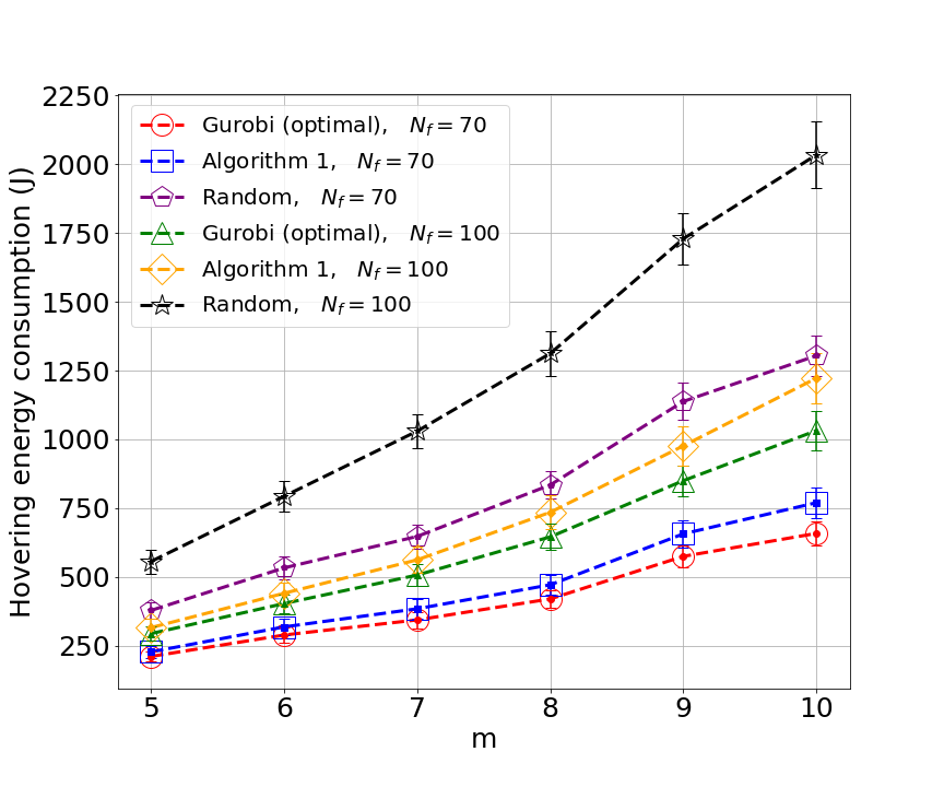
Fig. 8 presents data on the average energy consumption for different values of . The confidence intervals are depicted as vertical error bars around each data point. The results are quite evident: the proposed methods yield substantial improvements when compared to a random handover schedule. Specifically, for the case when , the proposed methods achieve approximately half the energy consumption of the random schedule, marking a significant improvement. It is worth noting that Algorithm 1 closely approaches the optimal performance, underscoring its effectiveness in handling the handover schedule. Fig. 8 also illustrates how and impact the level of hovering energy consumption. As expected, the energy consumption rises as and increase because more flows need to be handed over and more UAVs need to be replaced during the replacement process. We emphasize that in long missions requiring multiple phases of UAV replacements, the reduction in hovering energy consumption becomes even more significant compared to a random scheduling approach.
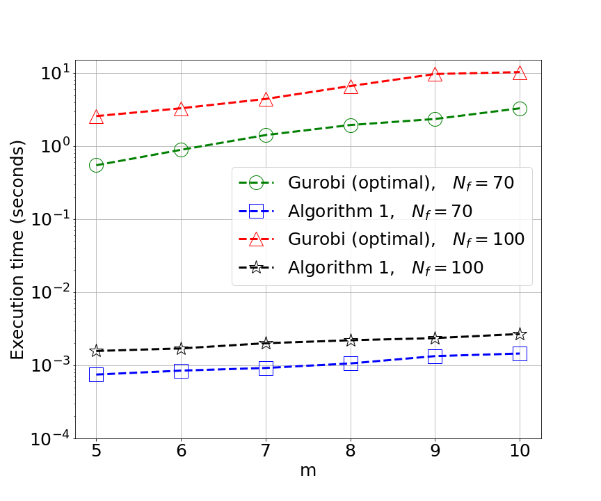
We also conducted a comparison of execution times for various methods, as depicted in Fig. 9. As evident from the data, Algorithm 1 exhibits execution time on the order of milliseconds, whereas the Gurobi solver, employed to find the optimal handover schedule, operates on the order of seconds. Furthermore, as anticipated, the execution time of all the proposed methods increases with the growth of because more flows need to be handed over.
VI Conclusion
UAVs encounter a significant challenge arising from energy constraints, often leading to the need for replacements. Effectively managing the handover of data flows during these replacements is crucial to avoiding interruptions in information transmission and minimizing energy consumption. This paper introduced an innovative approach to address the problem of energy-efficient UAV replacement in software-defined UAV networks by formulating it as an integer linear program. Our proposed method centers around establishing a strict total ordering relation for both UAVs and data flows.
Furthermore, we presented an efficient heuristic algorithm designed to mitigate the time complexity associated with solving the problem. Simulation experiments demonstrated that this heuristic closely approximates optimal solution while significantly reducing the computational burden of solving the problem.
References
- [1] L. Gupta, R. Jain, and G. Vaszkun, “Survey of important issues in UAV communication networks,” IEEE Commun. Surveys Tuts., vol. 18, no. 2, pp. 1123–1152, 2nd Quart., 2016.
- [2] M. Javad-Kalbasi and S. Valaee, ”Re-configuration of UAV Relays in 6G Networks,” 2021 IEEE International Conference on Communications Workshops (ICC Workshops), Montreal, QC, Canada, 2021, pp. 1-6.
- [3] M. Ohleger, G. G. Xie, and J. H. Gibson, “Extending UAV video dissemination via seamless handover: A proof of concept evaluation of the IEEE 802.21 standard,” in Proc. 46th Hawaii Int. Conf. Syst. Sci. (HICSS’13), Jan. 2013, pp. 5106–5114.
- [4] C.-W. Lan, C.-J. Wu, H.-J. Shen, H.-C. Lin, P.-J. Chu, and C.-F. Hsu, “Development of the autonomous battery replacement system on the unmanned ground vehicle for the drone endurance,” in proc. Int. Conf. Fuzzy Theory and Its Applications (iFUZZY), Hsinchu, Taiwan, Nov. 2020, pp. 1–4.
- [5] Y. Guetta and A. Shapiro, “On-board physical battery replacement system and procedure for drones during flight,” IEEE Robotics and Automation Lett., vol. 7, no. 4, pp. 9755–9762, Oct. 2022.
- [6] V. Sanchez-Aguero, F. Valera, I. Vidal, C. Tipantu˜na, and X. Hesselbach, “Energy-aware management in multi-UAV deployments: Modelling and strategies,” Sensors, vol. 20, no. 10, May 2020.
- [7] A. N. Patra, P. A. Regis, and S. Sengupta, “Dynamic self-reconfiguration of unmanned aerial vehicles to serve overloaded hotspot cells,” Computers & Electrical Engineering, vol. 75, pp. 77–89, May 2019.
- [8] Bhola, C.-C. Lai, and L.-C. Wang, “The outage-free replacement problem in unmanned aerial vehicle base stations,” IEEE Trans. Veh. Technol., vol. 70, no. 12, pp. 13 390–13 395, Dec. 2021.
- [9] M. Shan and X. Zhang, “Multi-UAV path planning model with multiple battery recharge points,” in Proc. Int. Conf. Dependable Syst. and their Applications (DSA), Wulumuqi, China, Aug. 2022, pp. 832–837.
- [10] N. Gupta, S. Agarwal, and D. Mishra, “Multi-UAV replacement and trajectory design for coverage continuity,” in Proc. IEEE Int. Conf. Commun. (ICC), Seoul, South Korea, Aug. 2022, pp. 1–6.
- [11] N. Gupta, S. Agarwal, D. Mishra and B. Kumbhani, “Trajectory and Resource Allocation for UAV Replacement to Provide Uninterrupted Service,” IEEE Transactions on Communications, doi: 10.1109/TCOMM.2023.3307559.
- [12] G. Wang, G. Feng, T. Q. S. Quek, S. Qin, R. Wen, and W. Tan, “Reconfiguration in network slicing—optimizing the profit and performance,” IEEE Trans. Netw. Service Manage., vol. 16, no. 2, pp. 591–605, Jun. 2019.
- [13] K.-T. Foerster, S. Schmid, and S. Vissicchio, “Survey of consistent software-defined network updates,” 2018, arXiv:1609.02305. [Online]. Available: https://arxiv.org/abs/1609.02305
- [14] H. Sufiev and Y. Haddad, “A dynamic load balancing architecture for SDN,” in Proc. IEEE Int. Conf. Sci. Elect. Eng. (ICSEE), Eilat, Israel, Nov. 2016, pp. 1–3.
- [15] H. Xu, Z. Yu, X.-Y. Li, L. Huang, C. Qian, T. Jung, “Joint route selection and update scheduling for low-latency update in sdns,” sdns, IEEE/ACM Trans. Netw. 25(5) (2017) 3073–3087.
- [16] H. Song, S. Guo, P. Li, and G. Liu, “Fcnr: fast and consistent network reconfiguration with low latency for sdn,” Computer Networks, vol. 193, p. 108113, 2021.
- [17] K. H. Rosen, Discrete Mathematics and Its Application, 6th ed. New York, NY, USA: McGraw-Hill, 2007.
- [18] M. B. Ghorbel, D. Rodríguez-Duarte, H. Ghazzai, M. J. Hossain, and H. Menouar, “Joint position and travel path optimization for energy efficient wireless data gathering using unmanned aerial vehicles,” in IEEE Trans. Veh. Technol., vol. 68, no. 3, pp. 2165-2175, Mar. 2019.
- [19] M. S. Al-Abiad, M. Javad-Kalbasi, and S. Valaee, “Maximizing network connectivity for UAV communications via reconfigurable intelligent surfaces”, 2023 IEEE Global Communication Conference, Kuala Lumpur, Malaysia, 2023, pp. 6395-6400.
- [20] M. Saif, M. Javad-Kalbasi and S. Valaee, ”Effectiveness of Reconfigurable Intelligent Surfaces to Enhance Connectivity in UAV Networks,” in IEEE Transactions on Wireless Communications, doi: 10.1109/TWC.2024.3476422.
- [21] M. Javad-Kalbasi, M. S. Al-Abiad, and S. Valaee, “Energy efficient communications in RIS-assisted UAV networks based on genetic algorithm”, 2023 IEEE Global Communication Conference, Kuala Lumpur, Malaysia, 2023, pp. 5901-5906.
- [22] C. Robert and G. Casella, “Monte carlo statistical methods,” Springer Science and Business Media, 2013.