Beam-driven plasma-wakefield acceleration
Abstract
Beam-driven plasma-wakefield acceleration (PWFA) has emerged as a transformative technology with the potential to revolutionize the field of particle acceleration, especially toward compact accelerators for high-energy and high-power applications. Charged particle beams are used to excite density waves in plasma with accelerating fields reaching up to , thousands of times stronger than the fields provided by radio-frequency cavities. Plasma-wakefield-accelerator research has matured over the span of four decades from basic concepts and proof-of-principle experiments to a rich and rapidly progressing sub-field with dedicated experimental facilities and state-of-the-art simulation codes. We review the physics, including theory of linear and nonlinear plasma wakefields as well as beam dynamics of both the wakefield driver and trailing bunches accelerating in the plasma wake, and address challenges associated with energy efficiency and preservation of beam quality. Advanced topics such as positron acceleration, self-modulation, internal injection, long-term plasma evolution and multistage acceleration are discussed. Simulation codes and major experiments are surveyed, spanning the use of electron, positron and proton bunches as wakefield drivers. Finally, we look ahead to future particle colliders and light sources based on plasma technology.
I Introduction
The particle accelerator has evolved from its inception in the early 1900’s to become a major work horse of scientific progress, ranging from subatomic physics and material science to cancer therapy and semi-conductor ion implantation. Paralleled only by the success of the laser and the computer, particle accelerators have experienced an exponential increase in capabilities over time, but at the expense of increasing size and cost. At the energy frontier, particle accelerators based on radio-frequency (rf) structures are fast approaching their fundamental limits: magnetic-field strength and synchrotron radiation limit circular accelerators, while material breakdown in metallic accelerating cavities limits linear accelerators. Circumventing these problems for future generations of high-energy-physics experiments will require a technological leap. One of the most promising ideas to this end is plasma-wakefield acceleration (PWFA), whereby an ionized gas is used as an accelerating medium. Immune to further breakdowns, the accelerating fields in a plasma can reach several orders of magnitude higher than in rf cavities, promising compact and potentially cheaper linear particle accelerators.
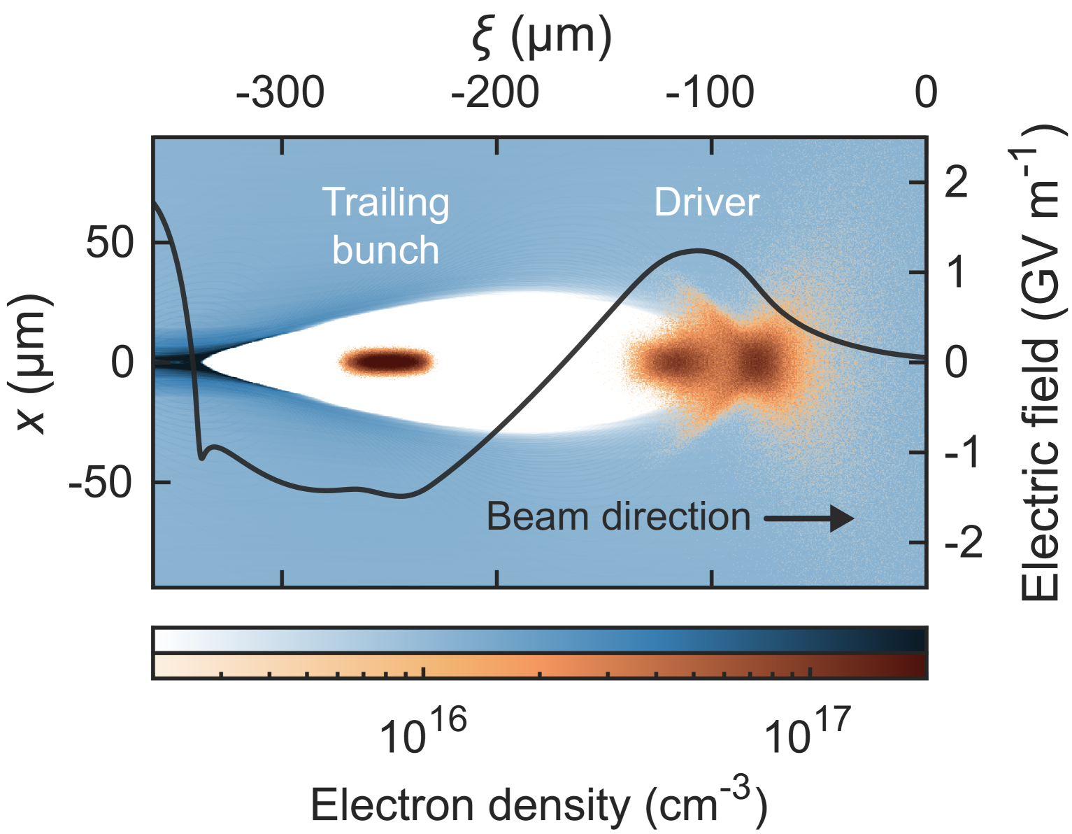
The basic principle behind plasma-wakefield acceleration is the following (see Fig. 1): an intense bunch of charged particles traveling through a plasma will repel electrons (if negatively charged) or attract electrons (if positively charged), which creates a region of charge separation behind the bunch. This region, called a plasma wake, has strong electric and magnetic fields that tend to rapidly restore quasi-neutrality. If another particle bunch is traveling at an appropriate distance behind the wake-driving bunch—approximately half a plasma wavelength—it can be accelerated by the electric field in the wake. This second bunch is sometimes referred to as the “trailing” (used in this Review), “accelerating”, “main” or “witness” bunch; the latter referring to its observation of the field inside the plasma wake, also known as the plasma wakefield. The characteristic strength of the wakefield is approximately given by the wavebreaking field [10, 104]
| (1) |
which for a typical plasma-electron density of order – cm-3 corresponds to an accelerating field of 1–; one to three orders of magnitude higher than in an rf accelerator (10–).
Plasma wakefields can be driven in many different ways. While this Review discusses plasma wakefields driven by beams of charged particles, the wakefield can also be driven by lasers—often referred to as laser-wakefield acceleration (LWFA) or laser–plasma acceleration. This closely related field of research was reviewed by Esarey et al. [132]. Within beam-driven plasma-wakefield acceleration, several different particles can be used: electron bunches are the most common [74, 433], and can drive either weak perturbations (linear regime) or strong density perturbations (nonlinear regime), each with their own advantages and drawbacks, as discussed in Sec. II.1. The nonlinear or blowout regime [426] is seen as particularly attractive for acceleration of electrons due to its large accelerating gradients and beam-quality-preserving focusing fields. Positively charged bunches—positrons or protons—can also be used to drive plasma wakes; for positrons this is similar to that of electrons in the linear regime [449, 118], but different and less ideal in the nonlinear or suck-in regime [269, 89], as discussed in Sec. III.1. Lastly, proton bunches, with their capacity for large energy content, interact similarly to positrons [66], but are mostly operated in the self-modulated regime [299, 260], where a long bunch interacts with the plasma to form a train of short bunches, due to the difficulty of producing short proton bunches—see Sec. III.2 for more details.
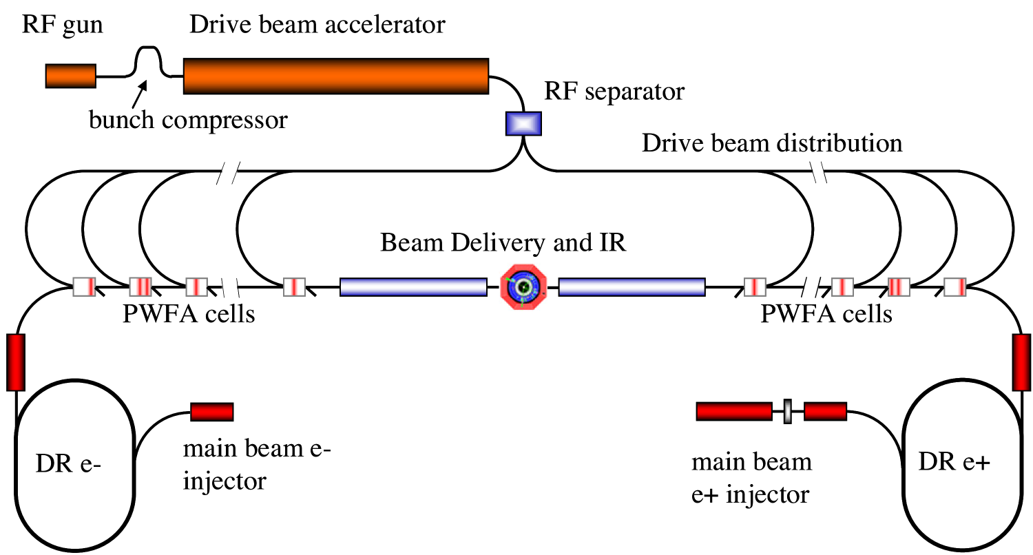
The key motivation for using a particle beam to drive the plasma wakefield is the potential for large energy gain and high energy efficiency—both demonstrated in landmark experiments performed at SLAC [48, 292]. These two aspects make PWFA particularly well suited for compact, high-average-power accelerators for photon science, such as an x-ray free-electron laser (FEL), and for high-energy physics, such as a linear collider [421, 456, 157], where the need for both high energy and high particle flux demands megawatts of beam power (see Fig. 2 and Sec. V.1). The wall-plug-to-beam energy efficiency of PWFA can be high because beam drivers can be produced with relatively high efficiency using klystrons [491, 279], as utilized in rf-based linear-collider concepts like CLIC [9]. Moreover, the energy content of these drivers can be efficiently extracted over long propagation distances, because these beams are self-guided in the plasma wake (no diffraction) and because the trailing bunch remains at a fixed distance behind the driver, since both bunches effectively travel at the speed of light (no dephasing). Combined with the possibility of using drivers with large energy content (i.e., joule-level electron/positron drivers or kilojoule-level proton drivers), this allows beam-driven plasma accelerators to reach high particle energies in the GeV–TeV range. For these reasons, beam drivers are considered appropriate for large-scale and high-power plasma-accelerator facilities.
While the benefits of PWFA are plentiful, any radical change in technology brings with it new challenges. Understanding and overcoming these issues has been the focal point of research—past and present. This includes questions concerning stability and long-distance propagation of beam drivers, which can be complicated by effects such as head erosion, mismatching, and the hosing instability—topics covered in Sec. II.2. Next, high beam quality, including low energy spread and small transverse emittance, is key to applications in high-energy physics and photon science. Accelerating a bunch while simultaneously ensuring high energy efficiency and high beam quality can be challenging, for instance due to tight tolerances on synchronization, misalignment, and bunch structure, as well as effects such as Coulomb scattering [342], hosing and beam-breakup instabilities [525, 266], as well as ion motion [429]. These topics are covered extensively in Sec. II.3. While solutions do exist for most issues regarding acceleration of electrons, the same is not true for positrons. This is because plasmas are inherently charge asymmetric; ions are much heavier than electrons. Positron acceleration is crucial for building an electron–positron collider, but is a challenging topic of research due to the complexity of its dynamics, as well as a lack of experimental facilities that provide suitable positron bunches. Nevertheless, recent progress in both experiments and theory shows promise—see Sec. III.1 or Cao et al. [70] for a review of positron acceleration in plasmas. Even if only electrons are needed, delivering the beam power required for FELs and linear colliders will be challenging. Accelerating particles at high repetition rate, typically kHz or higher, sets stringent demands on the plasma sources and the long-term plasma evolution that happen inside them—a topic covered in Sec. III.4. Lastly, in order to reach very high energies, multiple acceleration stages are likely required. So-called staging of plasma accelerators can be surprisingly space consuming due to the complexity of injecting and extracting drivers while simultaneously preserving the transverse and longitudinal phase space of the accelerating bunch—this topic is covered in Sec. III.5.
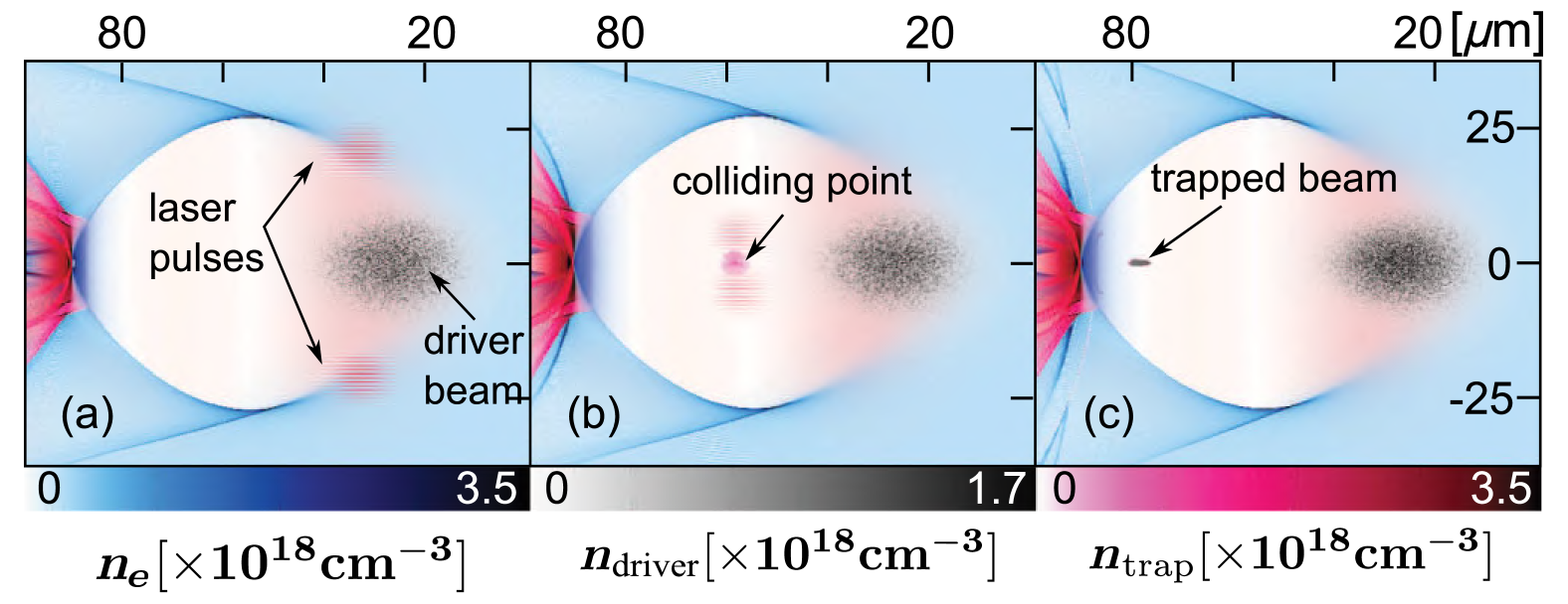
Beyond its use for rapidly accelerating particles, beam-driven plasma accelerators can also generate high-quality electron beams directly from the plasma, sometimes known as internal injection as opposed to external injection of bunches from external sources. This scheme promises so-called brightness transformation (brightness being the density in phase space), since the energy stored in a lower-quality drive beam can be converted to accelerate a higher-quality injected beam. If plasma electrons can experience the strong accelerating gradient for long enough to become relativistic, they will be injected into the plasma wake and continue to be accelerated just like externally injected electrons. This does not usually happen for plasma electrons in a uniform plasma, but can be achieved using two main techniques: (1) new electrons can be released by ionization within the plasma wake, by the intense fields of a laser pulse or a high-charge-density particle beam; or (2) existing plasma electrons that are part of the expelled electron sheath can be captured by a sudden reduction in phase velocity of the wake, for instance by a sharp downramp in plasma density. Numerous schemes exist that perform this injection in various ways, as detailed in Sec. III.3, some of which are common to laser-driven plasma accelerators and others that are only feasible in beam-driven plasma accelerators. One scheme in particular, the so-called plasma photocathode injection [205], colloquially known as “Trojan Horse” injection, exploits the advantages of beam drivers to generate beams with extremely high brightness. Here, a laser pulse travels collinearly with the beam driver, ionizing electrons from higher energy levels than the surrounding plasma—not normally possible with a laser driver, since that would itself ionize the higher levels. Importantly, these new electrons can be released directly on-axis, which means they can have very low transverse momentum and hence very low emittance. Such injected bunches can have normalized emittances at the nanometer scale (orders of magnitude lower than rf-photocathode sources), which combined with high current and small energy spread result in unprecedented beam brightness [198]. Figure 3 illustrates a variation on the plasma photocathode where the laser pulse (which ionizes the injected electrons) is coupled in transversely instead of collinearly [276].
The earliest ideas of plasma-wakefield acceleration can be traced back to Veksler [495] and Faĭnberg [135]—referred to as “coherent acceleration” or “collective acceleration” [265]. A review by Faĭnberg [137] details the foundational work performed in the USSR from 1950s onward, which included both theoretical [136] and experimental advances [242, 248]. While these developments were recognized in the US at the time [229], the research field in its modern form originated somewhat independently, starting with work led by John M. Dawson and collaborators at UCLA [105], who in the late 1970s discovered laser-driven plasma acceleration, as reported in a seminal paper by Tajima and Dawson [472]. Investigations into plasma acceleration driven instead by intense particle beams soon followed, both at UCLA, as reported by Chen et al. [74], and at SLAC National Accelerator Laboratory, as reported by Ruth et al. [433], driven in part by the possibility of performing such experiments in the SLAC linac [230]. At this time, the term “plasma wakefield” was coined, inspired by contemporary work on wakefields in rf accelerators [510, 28]; a change in nomenclature that may have contributed to the disconnect between modern and early literature.
From the start, two main methodologies have formed the pillars of the research field: theoretical studies based on numerical simulations, and experimental studies using beams from rf-based particle accelerators.
Particle-in-cell (PIC) simulations are the most commonly used numerical simulation for plasma accelerators. Such simulations place plasma and beam particles in a gridded simulation box, and move them in small time steps based on the electric and magnetic fields that evolve at each grid point. For high accuracy, billions of beam and plasma particles can be required, which means that simulations are often run on large supercomputers. While the most general PIC codes [156] work equally well for beam-driven and laser-driven plasma accelerators, some codes are optimized specifically for beam drivers. The most common optimization is the quasistatic approximation [465, 345], which makes use of the fact that the relativistic beam particles move on a significantly longer timescale than the plasma electrons, which allows the simulation to be split into independent longitudinal slices [214, 331]. Further, cylindrical symmetry or near-symmetry allows the system to be Fourier decomposed into its lowest azimuthal modes [280, 275], which dramatically speeds up the simulation. These numerical simulations, discussed briefly in Sec. IV.1, also play a vital role in supporting the experimental research, both for planning of future experiments and as a way to interpret existing results.
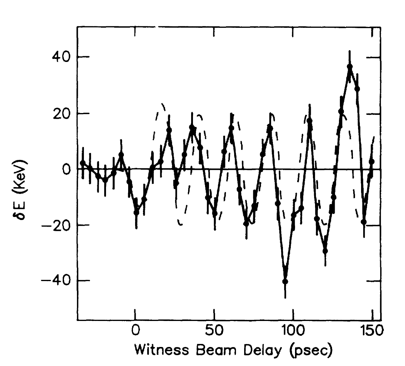
Experimental research was in many ways initiated by Rosenzweig et al. [427] with the first experimental observation of beam-driven plasma wakefields at Argonne National Laboratory. Two particle bunches were propagated through a -long plasma at a density of approximately . Varying the delay between the leading and trailing bunch, a small energy modulation was observed, as shown in Fig. 4, proving the existence of an oscillating plasma wakefield in the linear regime. Later experiments at the same facility also demonstrated nonlinear plasma wakefields [31, 33].
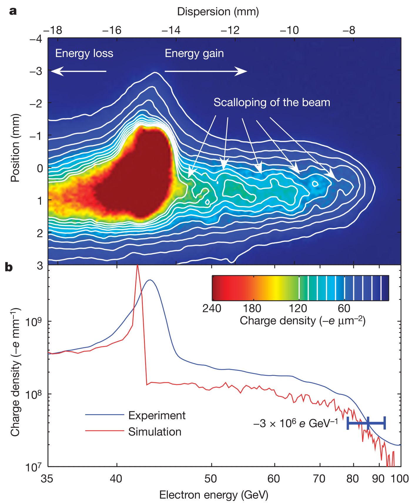
In the following decades, several important experimental milestones were reached. The first experiments to show the promise of beam-driven plasma acceleration were the demonstrations of large acceleration gradient [211] and energy gain [48], the latter by doubling the energy of electrons to in less than a meter (see Fig. 5). Later, high energy-transfer efficiency up to 30% was demonstrated in the first high-gradient plasma-wakefield accelerator using a distinct driver and trailing bunch [292]. A similar, but more precise experiment demonstrated the flattening of the accelerating field via optimal beam loading (see Sec. II.3.1), which enabled the preservation of energy spread while simultaneously providing energy-transfer efficiencies beyond 40% [290]. Further control of the beam quality was then demonstrated with the preservation of emittance [291]. Large transformer ratio (peak accelerating versus decelerating field) as high as 4.6 and 7.8 [296, 432] have also been shown, by careful shaping of the driver’s current profile. Studies of repetition rate found upper limits to be of order MHz or higher [102]. Next, PWFAs have been used for photon-science applications (see Sec. V.2), specifically to boost the energy in an FEL [401]. Utilizing these electron-driven plasma wakes, internal injection and acceleration of bunches with percent-level energy spread and micron-level emittance have been achieved using several different techniques, including ionization injection [378, 487, 488], as well as plasma photocathode and density-downramp injection [109, 251, 93, 155]. While all the above results were demonstrated with negatively charged electron beams, positively charged particle beams have also been used. Positrons have been both transported [210] and accelerated [46] in plasmas, first in the linear regime, and later also in the nonlinear regime [89] and in a hollow plasma channel [166]. Moreover, electrons were accelerated by a proton driver [6] that had been self-modulated into a train of shorter bunches [188, 7, 481]. Lastly, beam-driven plasma wakefields have been driven using electron bunches from a laser-wakefield accelerator, the so-called hybrid scheme (see Sec. IV.2.8), operating with a pair of drive–trailing bunches from the LWFA [184, 261] or with internal injection in the PWFA [93] that enabled the first demonstration of brightness transformation [155]. All these experiments, as well as the facilities in which they were performed, are discussed in Sec. IV.2.
Contemporary experimental research focuses on demonstrating the remaining milestones needed for large-scale applications. A particular focus is placed on preserving the beam quality—ultimately the 6D beam brightness—across long acceleration distances. Connected to this is also observation and suppression of the hosing or beam-breakup instability as well as ion motion. Demonstration of high overall energy-transfer efficiency is a stated goal at several facilities [233, 100], ideally in conjunction with beam-quality preservation. Work on demonstrating high-repetition-rate and high-average-power operation is ongoing, exploring both the physical limitations of the plasma-acceleration process as well as the technical limitations of the plasma-source design. Improvements in stability and reliability, of both plasmas and beams, is another aspect that is continuously maturing. Brightness transformation and ultrabright-beam generation based on internal injection is actively pursued, with a particular focus on the collinear plasma-photocathode technique. Such demonstrations are attempted both at facilities with rf-based electron sources as well as laser–plasma-based hybrid sources, where the latter may benefit from the intrinsic synchronization of its electron beam and injection laser. Lastly, positron experiments are planned to continue, but the lack of facilities providing high-energy positron beams means progress is uncertain.
Contemporary theoretical research is exploring the ultimate limitations of beam-driven plasma accelerators, focusing on at least six major topics: (1) identifying a viable positron-acceleration scheme, with numerous recent proposals [70]; (2) understanding how to maximize the energy efficiency while simultaneously suppressing transverse instabilities [266]; (3) staging of multiple plasma accelerators [281] compactly and without significant emittance growth; (4) performing self-consistent simulations of very long plasma accelerators with many stages, both accurately and at reduced computational cost; (5) understanding the long-term evolution of plasmas after beam–plasma interaction, and the repetition-rate and heating limits of plasma sources; (6) lastly, a number of collider-specific requirements are being studied, such as spin polarization and asymmetric-emittance beams.
In short, beam-driven plasma-wakefield acceleration is progressing towards demonstration of its promise as a compact accelerator technology for large-scale and high-power accelerator facilities. This Review summarizes the history and state-of-the-art of this exciting field of research. In the sections below, we first cover the basic physics of the beam–plasma interaction (Sec. II), as well as more advanced variations and aspects of PWFAs (Sec. III), followed by a review of the most important research methods and results, both theoretical and experimental (Sec. IV), a detailed look at proposed applications, with a particular focus on high-energy physics and photon science (Sec. V), and finally some concluding remarks looking toward the future of the field (Sec. VI).
II Physics
This section describes the three basic components of a beam-driven plasma-wakefield accelerator: the plasma wakefield, the beam driver and the trailing bunch. In particular, Sec. II.1 covers the short-timescale response of the plasma to a beam, while Secs. II.2 and II.3 describe the longer-timescale evolution of the driver and trailing bunch within the plasma wakefield, respectively.
II.1 Plasma wakefields
At the heart of PWFA is the excitation of a charge-density wave in the wake of a particle beam propagating in a plasma. This charge-density wave consists of a plasma-density perturbation accompanied by electromagnetic fields generated in the wake of the beam, referred to as plasma wakefields. In this section, we introduce the basic theory underlying plasma wakefields (Sec. II.1.1) and discuss different regimes for their excitation: linear (Sec. II.1.2), nonlinear (Sec. II.1.3), high-transformer-ratio (Sec. II.1.4) and hollow-channel wakefields (Sec. II.1.5), as well as the effect of plasma temperature and the phenomenon of wavebreaking (Sec. II.1.6). SI units are used throughout this Review.
II.1.1 Beams and plasmas
Beams and plasmas are collections of charged particles which interact with one another via Maxwell’s equations. Given a set of microscopic beam and plasma particle coordinates and momenta, we could in principle calculate the Lorentz force experienced by every particle and evolve the beam–plasma system forward in time. Yet this approach is not tractable in practice, and we are forced to use an approximate description of the beam–plasma system. The most generic approach to the problem, the kinetic description of the plasma and the beam, is to replace our set of particle coordinates and momenta with a distribution which describes the probability of finding a particle at a given position and momentum and at a given time . The six-dimensional space is referred to as the phase space. In beam physics, we associate the volume of phase space occupied by beam particles with the beam emittance [219, 416, 455] (see Sec. II.2.1).
In the absence of collisions between particles, the evolution of the distribution function for a given particle species (e.g., beam electrons or plasma electrons) is described by the Vlasov equation [175, 258]
| (2) |
where and are the species particle mass and the relativistic Lorentz factor, respectively, is the force acting on the particle species and differentiates with respect to the momentum variable. The assertion is a statement of Liouville’s theorem: under the action of conservative forces (i.e., no collisions or radiative damping) the phase-space volume occupied by the particles is conserved.
An even more simplified description can be obtained by adopting a fluid theory for the plasma, which can be derived by taking moments of the Vlasov equation. The species density is given by
| (3) |
The first-order moment of the Vlasov equation is found by integrating Eq. (2) over momentum space, which yields the plasma-fluid continuity equation
| (4) |
with the velocity. The second-order moment is found by multiplying Eq. (2) by and again integrating over momentum space. This yields the plasma-fluid equation of motion
| (5) |
where we have taken the cold fluid limit of zero temperature and identified as the Lorentz force, with and the electric and magnetic fields, and the species particle charge. Equations (4) and (5), along with Maxwell’s equations
| (6) | ||||
| (7) | ||||
| (8) | ||||
| (9) |
serve as the starting point for our discussion of linear plasma-wakefield theory. Here, and are the charge and current densities, and , and are the vacuum permittivity, permeability and speed of light, respectively.
II.1.2 Linear wakefields
In this section, we consider the effect of a low-density, ultrarelativistic particle beam propagating into a neutral, cold plasma with electron density . Here low density means that the beam density is much less than the plasma density: , or in other words, that the plasma is overdense, denser than the beam. The plasma ion mass is much larger than the plasma electron mass () and plasma ions are thus assumed to be immobile on the short plasma timescale relevant for plasma-wakefield acceleration, which is the timescale of the plasma electron response , where
| (10) |
is the plasma-electron frequency. With this assumption, the ions form a uniform stationary background and provide a restoring force for displaced plasma electrons (see Sec. II.3.2 for a review of the effect of ion motion for conditions where it cannot be neglected). Finally, we will also use the quasistatic approximation [465, 345] where the beam is assumed not to evolve during the timescale of the plasma response, or in other words that the beam timescale is much larger than the plasma-electron timescale.
The beam creates a small perturbation in the plasma electron density as it propagates through it. To first order, the plasma density is described by , where the plasma perturbation . The plasma is assumed to be at rest and free from any static electric and magnetic fields prior to the arrival of the electron beam. Therefore, the plasma-fluid velocity and electric field are also first-order perturbative quantities. Linearizing Eqs. (4), (5), and (6), we find
| (11) | ||||
| (12) | ||||
| (13) |
where the charge density has been used, with the charge density of the plasma and the charge density of the beam, being the elementary charge and the charge of a beam particle. Taking the divergence of Eq. (12) and combining the three equations yield the linear plasma wave equation
| (14) |
We consider an ultrarelativistic drive bunch with velocity and use the change of coordinates , where is the longitudinal coordinate along the beam propagation axis so that is the co-moving coordinate. We also use the quasistatic approximation , these derivatives being applied to any physical quantity describing the plasma wakefields or the driver. Equation (14) can then be re-expressed with the co-moving coordinate instead of , using ,
| (15) |
where is the plasma wavenumber. Equation (15) is a simple harmonic oscillator with a source term on the right-hand side given by the beam density. The solution for is a sinusoidal function of behind the drive beam, thus taking the form of a wave in the wake of the driver with a phase velocity equal to the speed of the driver, here assumed to be approximately . Using the Green’s function of Eq. (15), with the Heaviside step function, the solution for is obtained by convolving it with the beam profile
| (16) |
Transversely, the plasma-density perturbation is local and follows directly the transverse profile of the beam. The transverse extent of the density perturbation thus matches that of the beam.
The complete derivation for the fields , and in the linear plasma wakefield can be found in Keinigs and Jones [241] for the case with azimuthal symmetry where depends only on the radial cylindrical coordinate and on . Using Maxwell’s equations, going to the Fourier space of the coordinate and solving with respect to using the radial Green’s function or with Hankel transforms, the solutions for the fields can be obtained and involve Bessel functions as follows
| (17) | |||
| (18) | |||
| (19) |
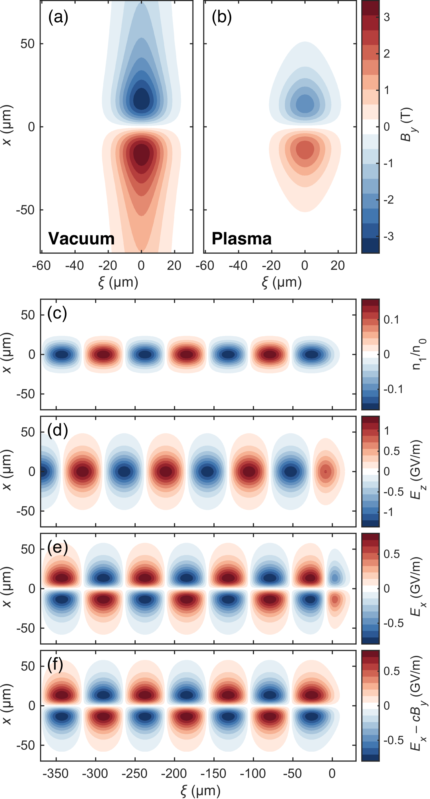
where (respectively ) is the larger (respectively smaller) of and , and and are the nth-order modified Bessel functions of the first and second kind, respectively. The terms involving in and correspond to the self-generated fields of the beam that are radially shielded by the plasma over a plasma skin depth [see Fig. 6(b)], which reduce to the self fields of a bare beam in the vacuum limit [see Fig. 6(a)]. The sinusoidal terms in (cosine term) and (sine term) correspond to the plasma wave, with the characteristic property that and oscillations are 90° out of phase [see Figs. 6(d) and (e)], and there is no field in the plasma wave behind the beam driver. Similarly to the self fields, the plasma wakefields are also shielded radially over a plasma skin depth. In contrast to the density perturbation , the fields are not necessarily local and can extend outside the beam. The transverse extent of the plasma wakefields matches the transverse extent of the shielded beam fields. For a small beam size, , the plasma wakefields (and the energy in the plasma wave) thus extend radially over a plasma skin depth , while for a large beam size, , they have the same transverse extent as that of the beam density [218].
A short drive beam experiences a transverse force that is focusing, and a longitudinal force that is decelerating, consistent with a transfer of energy from the drive beam to the plasma wave. For the trailing bunch, due to the 90° phase shift between and , exactly one quarter of the plasma wave period is simultaneously focusing and accelerating and thus suited for the acceleration and transport of the trailing bunch in the plasma. To maximize the energy-transfer efficiency from the plasma to the trailing bunch (see Sec. II.3.1), there should be as little energy as possible left in the plasma behind the trailing bunch. Given that the energy is localized where the fields are, a mismatch in transverse size between the wakefields of the driver and trailing bunches is very detrimental to the energy efficiency. The solution is to use small beams, , for both the driver and the trailing bunches, so that their wakefields have a similar transverse extent given by the plasma skin depth [218].
II.1.3 Nonlinear wakefields
When the ultrarelativistic particle beam has a bunch density that exceeds the plasma density, , the plasma can no longer screen the particle beam and the linear perturbation theory used in Sec. II.1.2, which assumes , cannot be applied. Transversely, which is relevant for fully three-dimensional wakefields, plasma electrons experience large excursions from their initial positions, being either sucked in (for a positively charged beam) or blown out (for a negatively charged beam) by the particle bunch [426]. In the one-dimensional (1D) limit (i.e., an infinitely wide beam), the motion is purely longitudinal and in a nonlinear wakefield, plasma electrons oscillate along the propagation axis with a maximum speed approaching that of the particle bunch (i.e., near the speed of light) and with an excursion of the order of the plasma wavelength.
In the quasistatic approximation where only depends on , and with , the equation for nonlinear wakefields in 1D is given in terms of the normalized electric potential , where is the electric potential, by [423, 256]
| (20) | ||||
| (21) |
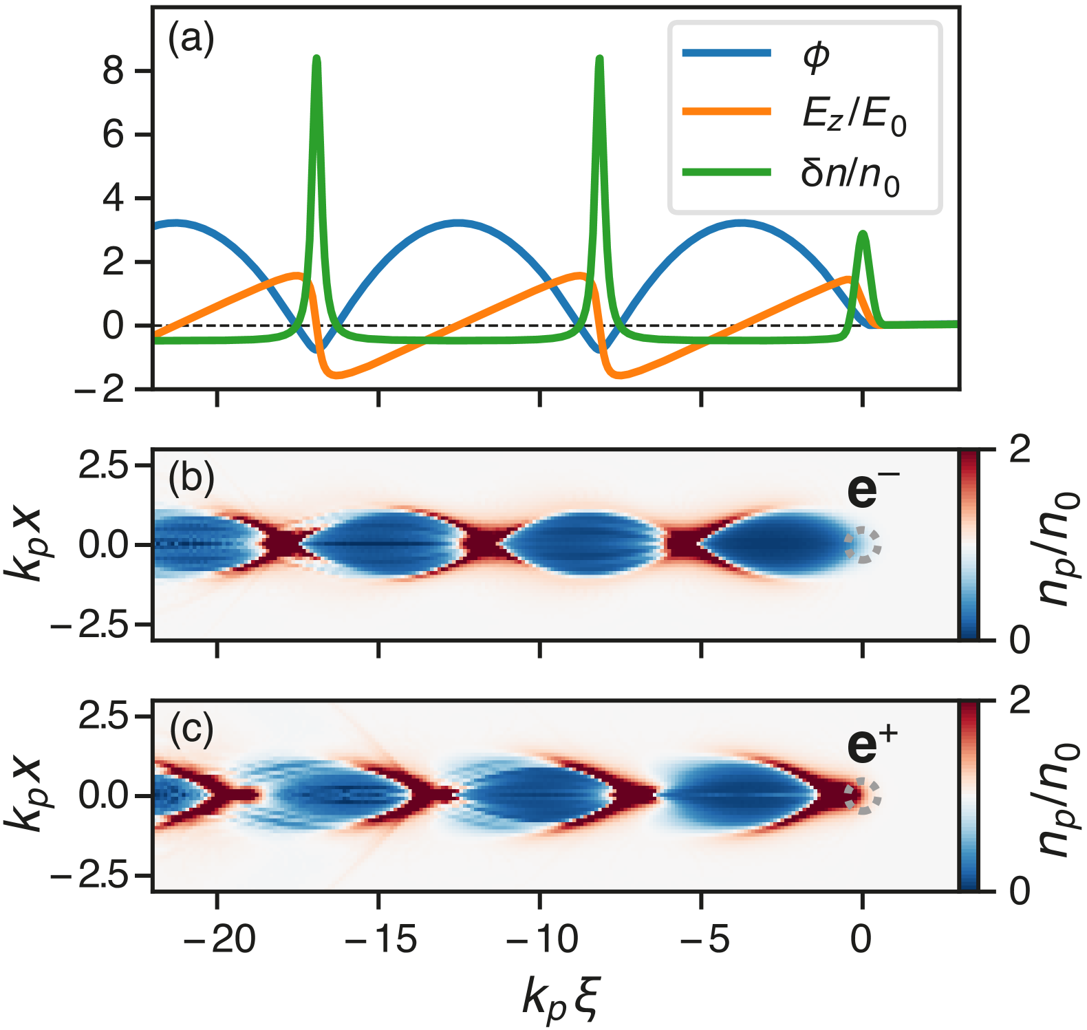
with [Eq. (1)] the normalizing electric field, referred to as the nonrelativistic cold-plasma wavebreaking field (see Sec. II.1.6). A 1D nonlinear wakefield obtained by solving Eqs. (20–21) is shown in Fig. 7(a).
For fully three-dimensional (3D) nonlinear wakefields, there is no complete and self-consistent analytical solution. We must therefore rely on numerical modeling (see Sec. IV.1) and/or phenomenological models to provide a qualitative and quantitative description of the nonlinear wakefield. In addition to the dimensionless parameter , in 3D the nonlinear wakefield also depends on the normalized current
| (22) |
or on the normalized bunch charge
| (23) |
where is the Alfvén current, is the peak current of the beam and the total number of particles in the beam. Beyond their definition in terms of and , their expression in terms of the beam size and the bunch length are given for Gaussian beams. The relevant parameter for very short bunches is [34, 425], while is more appropriate to describe wakefields driven by longer bunches [ [311]]. Based on these dimensionless parameters, the following regimes are defined:
-
•
: the linear regime (Sec. II.1.2);
-
•
and ( or ):
the nonrelativistic and nonlinear regime; -
•
and ( or ):
the relativistic and nonlinear regime.
For a negatively charged particle bunch (e.g., an electron beam) and , plasma electrons are expelled, or blown out, from the propagation axis by the particle bunch. Plasma electrons are then pulled back by the exposed plasma ions, overshooting the axis and setting up a nonlinear plasma oscillation. In this so-called blowout regime [426], the plasma wave takes the form of ion cavities surrounded by thin electron sheaths, as shown in Fig. 7(b) [268, 34, 425, 301, 312, 313].
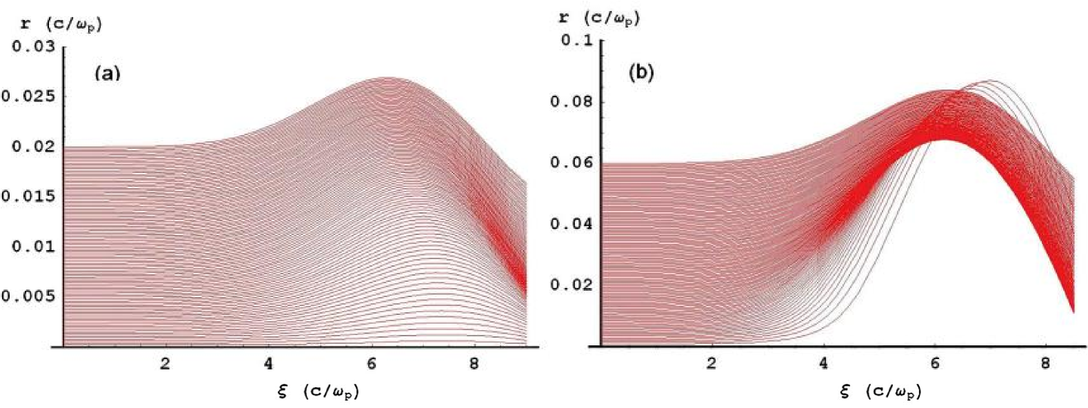
While the linear regime (see Sec. II.1.2) and the 1D nonlinear regime [Eqs. (20) and (21)] can be described by fluid theory, the blowout regime is characterized by transverse crossing of plasma-electron trajectories [313]—a phenomenon sometimes referred to as transverse wavebreaking. In this case, the fluid description must be abandoned in favor of a fully kinetic approach. As shown in Fig. 8, plasma electrons initially located closer to the axis can experience a stronger deflection than plasma electrons initially located further away from the axis, and their trajectories intersect each other. Trajectory crossing is in fact a necessary condition to reach the blowout regime [313], as otherwise a region void of plasma electrons cannot be established.
In addition to trajectory crossing, the blowout regime can also have another specific characteristic when the plasma response is relativistic ( or ): along the longitudinal axis, plasma electrons are initially pushed forward [34, 534], instead of backward as in the linear or 1D nonlinear regime. At the front of the particle bunch, the decelerating longitudinal electric field induces a backward motion for plasma electrons, but in a fully 3D configuration, the electric field of the bunch expels plasma electrons radially, while the bunch magnetic field pushes them longitudinally forward through ; a forward push that overcomes the decelerating electric field.
Importantly, the blowout regime has different scalings depending on the relativistic or nonrelativistic nature of the plasma response. A phenomenological model can be used to describe quantitatively the fields in the ion cavity of the blowout regime, by considering that blown-out plasma electrons form a thin electron sheath circulating around the ion cavity [301, 312, 313]. The dynamics can then be described in terms of two coupled systems: the electron sheath whose trajectory depends on the fields through its equation of motion, and the fields that depend on the sheath trajectory (the latter characterizing the source terms in Maxwell’s equations in this model). The plasma can then be considered as made of three parts: the ion cavity, the plasma-electron sheath, and the region outside with weak density perturbation, for which the response is linear [313].
Transversely, the linear-response region outside the ion cavity typically extends over a plasma skin depth . For weak drivers ( or ), the blowout radius is smaller than the plasma skin depth and as a result, the linear-response region dominates over the contribution of the blowout cavity when calculating . Thus, in this nonrelativistic blowout regime, despite the linear theory being invalid because , it still provides a useful estimate and scaling for [311].
On the other hand, for the relativistic blowout regime ( or ), the blowout radius is larger than the plasma skin depth, and the linear theory predictions and scalings fail. For ultrarelativistic blowout ( or ), the blowout cavity provides the dominant contribution and the coupled sheath–field system can be simplified and described by a single differential equation for the electron sheath trajectory [312, 313]:
| (24) | ||||
| (25) |
where is the normalized current profile of the electron beam when , and is related to the parameter by . This model does not take into account ion motion, whose effect is discussed in Sec. II.3.2. Near the maximum of and for zero right-hand side in Eq. (24), the trajectory resembles that of a circle [312]; in this case [ being the location of the maximum of ], consistent with expressions obtained for the so-called bubble regime in laser-wakefield accelerators, where the bubble shape of the ion cavity is assumed [252, 404]. At the rear of the blowout cavity, the sheath-trajectory equation differs significantly from a circle and leads to the characteristic spike of , a feature not reproduced in bubble models.
A more accurate description than Eq. (24) can be obtained by using a multi-sheath model [99] or an energy-conserving theory [176]. The latter self-consistent theory not only satisfies the energy-conservation law, but also provides much higher accuracy in a wide range of parameters, without the need to fit external parameters. It is not limited to the description of very large blowout cavities with , and can be used for . The energy-conserving sheath trajectory equation is given by [176]
| (26) |
which simplifies to Eq. (24) for ultrarelativistic blowouts with .
For moderate bunch length (), the maximum blowout radius can be estimated by equating the repulsive space-charge force from the electron drive beam and the restoring force from the wakefield; the exact numerical coefficient in this estimate can be verified with simulations. It is given by [313, 311]
| (27) |
This relation can also be obtained by considering the equilibrium radius for a beam with a constant current ; the first two terms of the left-hand side of Eq. (26) go to zero. For short bunches with , it is the initial kick given to plasma electrons by the drive bunch that determines the maximum blowout radius . A similar relationship exists between and of the form , with for short and small drivers [513].
At the rear of the blowout cavity, an electron beam can experience an accelerating longitudinal electric field, and the field properties are ideal for preserving high beam quality. Because the blowout cavity is devoid of plasma electrons and thus has a uniform charge density inside associated with the immobile ions (ignoring for now ion motion, see Sec. II.3.2), the transverse focusing force, ) for axisymmetric beams, is linear in and independent of . This is a key property that allows for the preservation of transverse emittance [85]. Furthermore, the Panofsky-Wenzel theorem [383] implies that
| (28) |
and thus the uniformity of along () ensures that is independent of and that the slice energy spread can be preserved: all particles from a given slice experience the same accelerating field . These properties make the blowout regime a very promising candidate for highly efficient and high-quality plasma-based electron acceleration in PWFA (see Sec. II.3).
In contrast to negatively charged drivers, the case of a bunch of positively charged particles (i.e., positrons or protons) exhibits some specific properties in the nonlinear regime . Plasma electrons are sucked in by a positively charged drive bunch instead of being expelled as in the blowout regime. As a result, plasma electrons flow through the drive particle bunch, and a sheath trajectory model as in Eq. (26) is not applicable to describe this phase of the wakefield formation. However, for bunches that are sufficiently short so that most plasma electrons cross the propagation axis behind the bunch, an ion cavity similar to the one of the blowout regime can be formed, as shown in Fig. 7(c), because sucked-in plasma electrons are crossing and overshooting the axis in a region void of drive-bunch particles. Once plasma electrons have overshot the axis, an ion cavity is naturally formed with properties similar to that described above. This ion-cavity formation was reported in both nonlinear proton-driven PWFA [66] and nonlinear positron-driven PWFA [89]. In the latter report, it was shown that a longer positron drive bunch would lead to a more complicated wakefield where the ion cavity is not void of plasma electrons (see Sec. II.3.1 and Fig. 18), opening the possibility for positron acceleration (see Sec. III.1). In general, in the strongly nonlinear regime with , a long positively charged drive bunch can lead to multiple oscillations of plasma electrons around the propagation axis if , where is the plasma-electron frequency associated with the particle-bunch density. In this situation, the on-axis plasma electron density as well as the focusing force have strong oscillations along , and the Panofsky-Wenzel theorem implies that is strongly non-uniform transversely. Such a non-ideal field structure can however be tolerable for a drive particle bunch, where preservation of beam quality is not important, as long as the drive bunch can efficiently transfer its energy to the plasma wakefields.
A critical quantity for the theoretical description of 3D nonlinear wakefields, underlying the previously discussed models, is the pseudo-potential , with the longitudinal component of the normalized vector potential and the vector potential. While the electric potential is sufficient to capture the physics of nonlinear plasma wakefields in 1D, as described by Eqs. (20) and (21), is required to account for the fully electromagnetic character of 3D nonlinear wakefields. In the quasistatic approximation, which represents a symmetry, the system is invariant under the transformation , , and the gauge-dependent potential can be elevated to the gauge-independent pseudo-potential that fully determines the longitudinal and transverse wakefields [47]:
| (29) | |||
| (30) |
The variable is thus sufficient to predict the dynamics of the drive and trailing particle beams that propagate at nearly the speed of light along the axis. The quantity obeys a Poisson-like equation in the transverse plane, with as a source term [313]. The mathematical identity provides an immediate proof of the Panofsky-Wenzel theorem [Eq. (28)] in the quasistatic case. In addition to being a powerful theoretical tool for modeling 3D nonlinear wakefields, also plays a fundamental role in the Hamiltonian dynamics of a test electron and thus on the physics of internal injection (a test particle is assumed not to influence the rest of the system). Applying Noether’s theorem, the quasistatic symmetry implies the existence of a constant of motion given by for the test electron, where and are the Hamiltonian and longitudinal component of the canonical momentum of the test electron, respectively. This conserved quantity provides a direct and fundamental relationship between the gauge-invariant and the kinetic energy and forward momentum of the test electron [345]:
| (31) |
Using initial conditions to determine the constant, this identity provides a condition for trapping a test electron into the wakefield, as discussed in Sec. III.3. The wake phase velocity , assumed to be until now, can also be accounted for in the quasistatic symmetry, in which case Eq. (31) is replaced by Eq. (78), and .
II.1.4 High-transformer-ratio wakefields
To maximize the energy that can be gained by the trailing bunch in a single plasma accelerator stage while keeping the driver energy at a reasonable level, the so-called transformer ratio , defined as
| (32) |
has to be increased, where is the maximum accelerating field experienced by the trailing bunch and is the maximum decelerating field found in the driver. Indeed, for a drive-beam energy , the maximum energy gain for the trailing bunch is limited to . The transformer ratio is a property of the wakefield, and specific current profiles for the driver are required to generate high-transformer-ratio wakefields. In fact, the transformer ratio is a general characteristic for collinear wakefield acceleration [27] and is relevant to wakefields driven also in metallic and dielectric structures, in addition to plasmas. Importantly, in the linear regime, it was found that cannot be larger than 2 for a drive bunch whose current profile is symmetric about its midpoint [28]. Naturally, strategies to maximize and overcome the limit are based on asymmetric drive current profiles or asymmetric drive bunch trains [27, 76, 237, 426, 225, 375, 327, 143, 273, 469]. Interestingly, the key parameter to increase is not driving wakefields of higher amplitude . This was shown experimentally by Blumenfeld et al. [49] where increasing the drive peak current produced only a weak variation in . Instead, high transformer ratios are obtained by minimizing drive-beam deceleration, i.e. by decreasing as much as possible. This is done by using a long, linearly-ramped current profile (see Fig. 9), i.e. a long adiabatic rise of the beam current to transfer energy slowly from the drive beam to the plasma wakefield, followed by a rapid fall to set the plasma oscillation with large amplitude. A precursor bunch (i.e., just ahead of the driver) or a modified bunch head can also be used to improve the uniformity of along the drive bunch, as demonstrated experimentally by Roussel et al. [432].
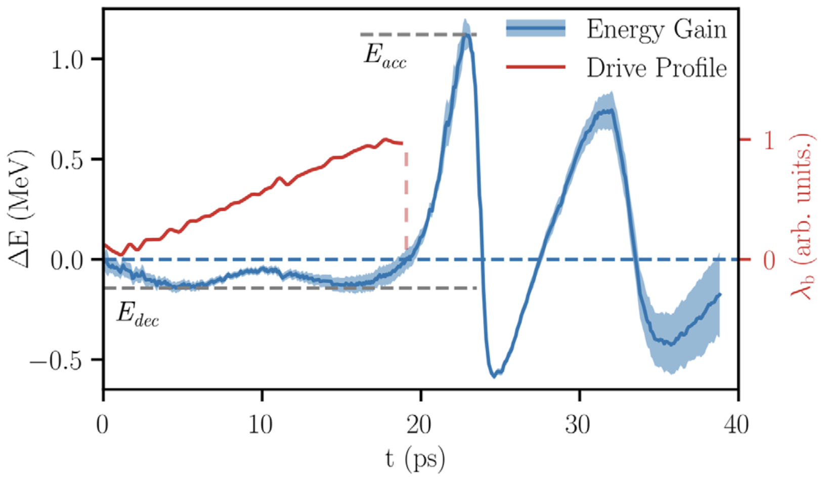
Experimentally, the first demonstrations of high-transformer-ratio wakefields for advanced accelerators were obtained for dielectric wakefield accelerators [226, 227] with [164]. In PWFA, two seminal results demonstrated experimentally transformer ratios of nearly 5 [296] and 8 [432] in the nonrelativistic and nonlinear regime. Loisch et al. [296] relied on the shaping of the photocathode laser temporal profile at the photoinjector to generate a ramped current profile for the drive electron beam, and used a short trailing electron bunch to probe , with energy gain of for the trailing bunch and maximum slice energy loss of for the drive bunch. Roussel et al. [432] used an emittance exchange (EEX) process to map the transverse coordinate to the longitudinal coordinate, thereby shaping the longitudinal current profile when using a beam mask in the plane transverse to the beam axis just before the EEX beamline. With a long trailing electron bunch, the longitudinal wakefield was measured in a single shot (see Fig. 9), allowing the dependence of high-transformer-ratio wakefields with the shape of the drive beam to be uncovered. The observed transformer ratio of nearly 8 was well in excess of the expected value of for such a drive-current profile and for single-mode linear wakefields [27], highlighting the potential of nonlinear (multimode) wakefields to enhance the transformer ratio further.
II.1.5 Hollow-channel plasma wakefields
As discussed in Sec. II.1.3, the nonlinear blowout regime is ideal for accelerating a trailing electron bunch in plasma. The transverse focusing forces are linear, the accelerating field is independent of transverse beam offset, and a properly loaded beam will be uniformly accelerated (see Sec. II.3.1). By contrast, the region of the nonlinear blowout wakefield that is both focusing and accelerating for positrons is too small to load a trailing positron bunch unless significant modifications are made to the wake, as discussed in Secs. III.1.1 and III.1.1.
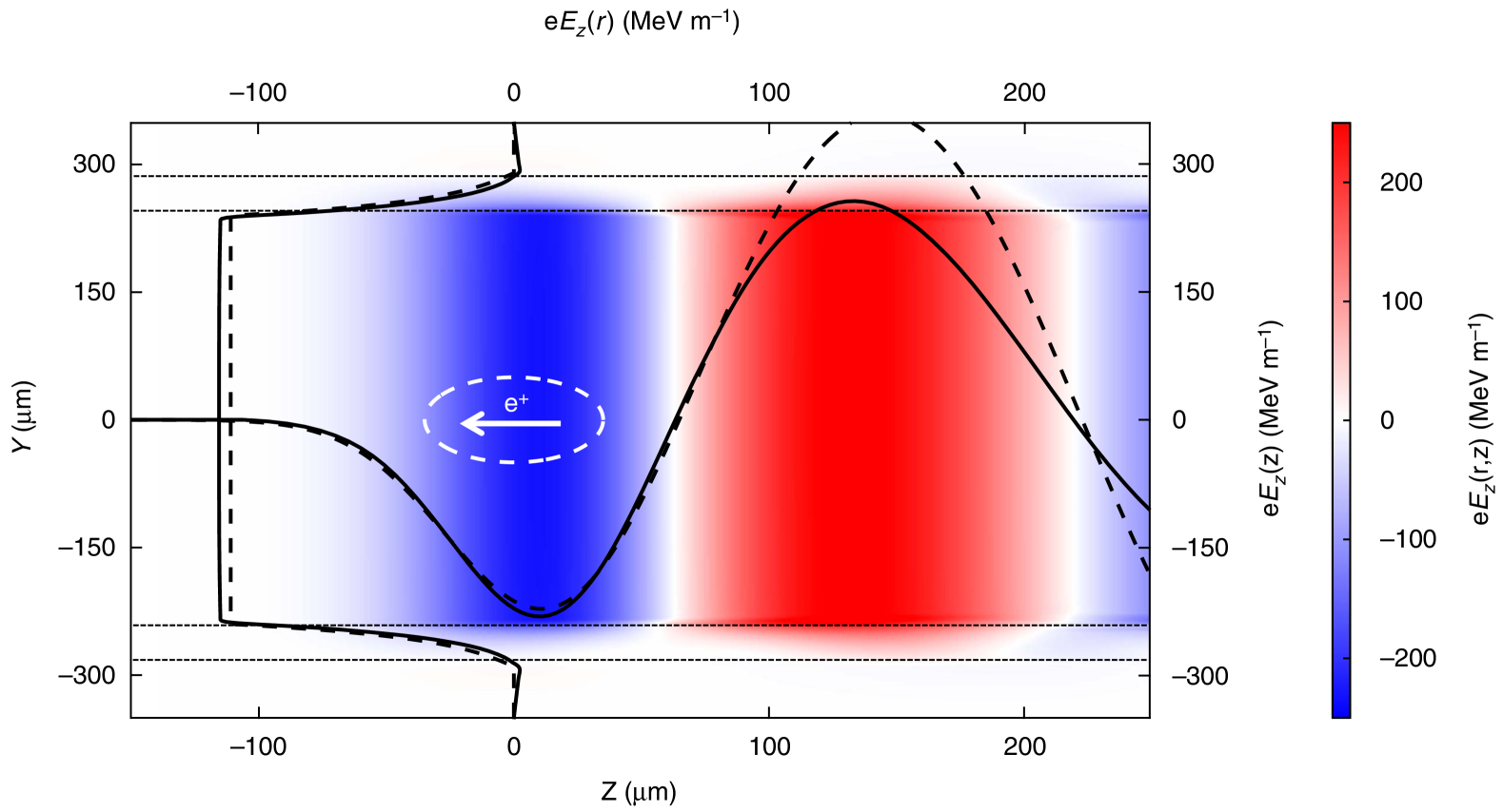
The linear hollow-channel plasma wakefield accelerator is a concept combining the symmetrization of the plasma response to beams of opposite charge [79, 78] and the absence of plasma constituents along the beam axis, resulting in no plasma focusing. In this scenario, an electron or positron beam propagates through a hollow tube of plasma. The beam drives a high-amplitude electromagnetic field inside the plasma channel. The electromagnetic fields are analogous to those excited by a beam transiting a structured waveguide [71] or a dielectric waveguide [376] and can be decomposed into components characterized by the azimuthal moment . For an on-axis beam driver, only the axisymmetric mode will be excited. In this case, the wakefield in the channel has desirable properties for accelerating a trailing bunch of electrons or positrons. Namely, the mode produces a radially uniform longitudinal field which extends to the plasma boundary (see Fig. 10), such that particles with different initial offsets with respect to the channel axis all gain energy at the same rate. The and components are equal and opposite, and all other field components are zero, so there is no transverse force acting on the beam particles due to the electromagnetic wakefield. The absence of plasma in the channel implies that there are no transverse forces from on-axis plasma electrons or ions. If the trailing bunch also propagates on-axis, it will not experience a transverse force due to the wake. The longitudinal wakefield excited by a single particle of charge located at is given by
| (33) |
where and are geometric factors from boundary conditions at the plasma inner radius and outer radius [169, 288]. If the inner radius is on the order of a few plasma skin depths, and the plasma wall is at least one skin depth thick, we find and .
If either the driver or trailing bunch is offset from the center of the channel, all higher azimuthal modes will be excited in addition to the mode. In particular, the beams will couple to the dipole mode which is always deflecting at short distances . The transverse wakefield excited by a single particle of charge located at with a small transverse offset is
| (34) |
where is a wavelength modification factor for the mode. Wakefields from arbitrary beams can be obtained by convolving the single-particle wakefield with the current profile. Note that the transverse wakefield scales as while the longitudinal wakefield scales as . The main challenge of the hollow-channel plasma wakefield accelerator is maintaining small offsets such that . In general, the transverse wakefield is deflecting away from the channel axis, and as the beam drifts toward the channel wall, it will excite a larger transverse wakefield, leading to stronger deflection. This is called the beam-breakup instability (BBU) and it has been studied extensively in the case of hollow-channel plasmas [450].
Experimental studies of the linear hollow-channel plasma wakefield accelerator in the context of positron acceleration (see Sec. III.1.2) have shown good agreement with these theoretical predictions and have highlighted the challenge associated with transverse wakefields [288] and BBU instability. Strategies to mitigate BBU in the hollow-channel plasma wakefield often revert to the re-introduction of plasma focusing via on-axis plasma electrons from the channel walls [see e.g. Zhou et al. [554] and Sec. III.1.1].
Going beyond the linear regime, nonlinear hollow-channel plasma wakefields in many ways resemble the blowout regime but without on-axis focusing, as described analytically by Golovanov et al. [177]. These wakes can sustain strong, longitudinally uniform accelerating fields by means of beam loading, as well as by superimposing an accelerating positron bunch on a decelerating electron bunch [555]. Here, the linear response is of similar importance to the nonlinear contribution associated with the blowout effect in the resulting field. However, further work is needed to explore strategies ensuring stability and mitigating BBU.
In practice, the hollow-channel plasma accelerator is an idealized concept that assumes zero plasma density (i.e., a vacuum) on-axis with a sharp transition to full density at the inner radius . Hollow channel plasmas that can be realized in the laboratory violate these assumptions (see Sec. III.1 and IV.2.4). For example, the channel may contain un-ionized, on-axis vapor [244, 166], the channel may contain low-density plasma [448], or the plasma transition at the boundary is not sharp. In the latter case, there will be a region of the boundary where the wavenumber of the plasma matches the wavenumber of the hollow channel mode [461]. In this case, the electrostatic plasma mode is excited, which removes energy from the accelerating mode and further disrupts the plasma boundary. This issue is avoided if the transition region is narrow ().
II.1.6 Wavebreaking and plasma temperature
Wavebreaking is sometimes used to refer to the breakdown of the fluid description for the plasma, which is associated with trajectory crossing, as discussed in Sec. II.1.3 and depicted in Fig. 8. In this restrictive sense, the wavebreaking limit can be understood as the maximum amplitude of the plasma wave allowed in the fluid model. Wavebreaking is, however, more generally understood as the breaking of the regular structure of the wake, which can lead to trapping of some plasma electrons into the wake [see discussion in Lu [310] on the definition of wavebreaking]. Longitudinal wavebreaking [10] occurs when the longitudinal oscillation of plasma electrons becomes so large that these electrons can be injected into the accelerating portion of the wake—the wave breaks because a large population of plasma electrons no longer participates in maintaining the wave, and instead moves with it. Transverse wavebreaking can occur due to the curvature of plasma-wake phase fronts, which increases with the distance behind the driver [62]. When the radius of curvature of the phase front is comparable to the plasma-electron displacement, the transverse mixing of electron trajectories breaks the wave with the generation of fast electrons near the axis. For stronger drivers in the blowout regime, transverse wavebreaking or self-injection [87] directly results from plasma-sheath electrons circulating around the ion cavity and becoming trapped at the rear of the cavity. Wavebreaking and particle trapping can be detrimental by producing “dark current” in the plasma wake, reducing the accelerating field and the acceleration efficiency [487, 315]. It can also be desired as a means to inject a new beam of electrons into the wake [340, 87], however injection mechanisms that are better controlled than wavebreaking and provide higher quality beams are generally preferred (see Sec. III.3).
In one dimension, the cold relativistic wavebreaking field is [10], with the Lorentz factor associated with the phase velocity of the plasma wave. For particle-beam drivers, is very large and thus can largely exceed the cold nonrelativistic wavebreaking field . However, when accounting for the plasma temperature, some fast electrons in the tail of the thermal velocity distribution may be trapped in the wake, thus leading to wavebreaking. In the limit relevant for PWFA [see Esarey et al. [132] for a discussion of warm wavebreaking relevant to LWFA], the warm relativistic wavebreaking field is given by [424, 238], where is the initial electron plasma temperature and is the Boltzmann constant.
Beyond the role of plasma temperature on the wavebreaking field, the thermal velocity spread of plasma electrons can also smooth out the field structure of the wake, for example reducing the electric-field spike at the rear of the ion cavity in the blowout regime [300, 223]. It was also suggested by Cao [69] that the electron plasma temperature can impact beam-breakup instability and ion motion (discussed in Secs. II.3.2 and II.3.2), while an ion temperature in the few hundred keV range can completely suppress ion motion [170].
Plasma temperature is particularly important in the context of positron acceleration (see Sec. III.1), where smoothing the field structure and broadening the plasma electron filament used for positron focusing can be essential to linearize the transverse wakefields and to improve the uniformity of longitudinal wakefields [462, 514, 112, 70]. Plasma-temperature effects are also expected to play a key role in high-repetition-rate and high-average-power plasma accelerators due to the inherent inefficiencies in the plasma-wakefield process resulting in large amounts of energy being deposited in the plasma. This stored energy is expected to manifest in the form of hot plasma electrons and ions, modifying the wakefield properties from the cold case and thus presenting the challenge of generating consistent acceleration for each consecutive bunch (see Sec. III.4).
II.2 Driver propagation
Understanding and optimizing the propagation of the drive beam in the plasma is key to achieving efficient transfer of energy from the driver to the plasma wake as well as high-quality acceleration of a trailing bunch (covered in Sec. II.3). Indeed, although a driver can initially excite a plasma wakefield with ideal characteristics for accelerating a trailing bunch, driver evolution during propagation in the plasma can lead to a changing and eventually sub-optimal plasma wakefield. Stable driver propagation and, more specifically, a stable plasma wakefield are thus generally desired. This requires keeping the driver focused over long distances, achievable through self-guiding (see Sec. II.2.1), avoiding so-called “head erosion” or loss of charge from the front of the driver (see Sec. II.2.2), and avoiding transverse instabilities (see Secs. II.2.3 and II.2.4). Having mitigated all the above-mentioned effects, the aim is to minimize the energy left in the driver at the end of a plasma-accelerator stage—so-called driver-energy depletion (see Sec. II.2.5).
II.2.1 Guiding, matching and the envelope equation
For high-energy particle beams propagating in vacuum, space-charge forces are generally negligible and the beam particles move ballistically. When the drive beam is focused in vacuum to a beam size , it can maintain this beam size (to within a factor ) over a distance given by the beta function [with the geometric emittance, see the definition in Eq. (39) below], analogous to the Rayleigh length for a laser pulse. is typically much larger for particle beams (meter scale) than for a laser pulse (mm–cm scale), which is generally considered as an advantage of particle beam drivers (PWFA) over laser drivers (LWFA).
In the plasma, beam particles experience the transverse focusing force of the plasma wakefield, which provides guiding to the particle beam driver over distances much larger than . To understand this, consider the simplest case where beam particles are subjected to a linear focusing force, with -component and the gradient of the focusing force. The -component of the equation of motion for a relativistic beam particle can then be rewritten as
| (35) |
with the betatron wavenumber, the Lorentz factor of the beam particle (here assumed to be constant) and its mass. The solution is a simple harmonic oscillation around the propagation axis, with a period given by . To go from the single-particle dynamics to the dynamics of the whole beam, it is useful to introduce the Twiss or Courant-Snyder parameters [94]:
| (36) | ||||
| (37) | ||||
| (38) |
The geometric emittance [153], given by
| (39) |
is a key beam parameter, as it represents the area occupied by the beam in the trace space () and quantifies the transverse quality of the beam; that is, its focusability—how small it can be focused for a given numerical aperture—or parallelism—how long it can maintain its size for a given beam size [219]. The normalized emittance, representing the area occupied by the beam in the normalized phase space (), can be a better representation of the transverse quality when the beam accelerates (because it is a conserved quantity during acceleration). It is given by
| (40) |
For a mono-energetic beam, , but the relationship between and for finite energy spread can be more complicated and depends on the correlation between and the transverse trace/phase space [153, 18, 338, 277].
From the single-particle equation [Eq. (35)], the differential equations for the first two Twiss parameters are
| (41) |
and the second-order equation for the evolution of the beam size is
| (42) |
the so-called envelope equation. In general, the solution to Eq. (42) is a beam-envelope oscillation between and at twice the betatron frequency (i.e., with a period of ). Assuming that at the entrance of the plasma, and and thus , the beam size can oscillate but always remains smaller than , and the beam can thus be effectively guided inside the plasma over very long distances, much longer than the initial beta function , as long as the plasma provides a focusing force to the beam.

The beam is said to be “matched” to the plasma focusing force if there is no beam-envelope oscillation [see Fig. 11(a)], which corresponds to when and are independent of . This matching condition is satisfied if and , that is for [32, 22, 321, 332]
| (43) |
Experimentally, transverse beam dynamics were first characterized in electron-driven PWFA in the blowout regime using a single drive bunch, and the beam was observed to undergo multiple envelope oscillations when mismatched [83]; see Fig. 11(b). By properly choosing the beam and plasma parameters, matching was achieved and the beam propagated through the plasma over a distance of more than 12 beta functions without envelope oscillations [356].
The above discussion illustrates the principle of how a beam can be guided in a plasma and how it can be matched to the plasma focusing force to avoid beam-envelope oscillations. In a realistic scenario, the driver loses energy by exciting the plasma wakefield, and thus and vary during propagation. At the entrance and exit of the plasma, the driver can also propagate in a plasma-density ramp, leading to -dependent . Moreover, the plasma focusing force and can be different for different slices of the drive beam, thus being -dependent, and finally, the focusing force can be nonlinear in the transverse coordinates. Note that Eq. (35) assumes a linear focusing force. In the blowout regime (see Sec. II.1.3), most of the drive particles are within the blowout ion cavity and thus experience a -independent linear focusing force with . The most important refinement arises from an additional term (resp. ) to be added to the RHS of Eq. (35) [respectively RHS of Eq. (42)] due to the variation of [255, 321], as well as to include the description of plasma-density ramps, which need to be accounted for to match the beam in the plateau of the plasma density profile [321, 154, 120, 538, 20]. Furthermore, when plasma electrons are blown out, it takes a finite distance in for the blowout cavity to form. Thus, the particles at the head of the drive bunch do not experience a -independent linear focusing force, and the modeling of beam dynamics at the head is more complicated and results in so-called head erosion, which is discussed in Sec. II.2.2.
In addition to the self-guiding provided by the wakefield itself, it is possible to employ external guiding. In LWFAs, this is done via a transverse plasma-density gradient (quadratic increase with radius) to guide the laser driver as in an optical fiber [64, 271], whereas in PWFAs the opposite density gradient is required: the density must be highest on axis [354, 4]. An external magnetic field can also be applied, either via quadrupole magnets [407] or active plasma lensing [490]; the latter involves conducting a longitudinal discharge current through the plasma during the acceleration process.
II.2.2 Head erosion
The physics of head erosion can be understood as follows: while the particles in the bulk of the drive beam are guided by the plasma focusing force, the particles at the very head of the beam do not experience such a force because the plasma wakefield has not yet been established. As a result, the beam head expands due to its finite emittance, and is effectively lost when propagating for distances larger than . The loss of particles at the head of the beam shifts the start of the wakefield backwards, causing the next-to-leading particles to propagate ahead of the guiding fields of the wake. This leads to a continuous erosion of the beam, as illustrated in Fig. 12.
Emittance-driven head erosion [58, 257] was considered as an important limitation for PWFA in early developments [32], in particular because it sets stringent constraints on the drive-beam emittance [421], it reduces the wakefield amplitude and gives rise to a phase slippage of the plasma wakefield, moving it backward in the beam frame [33]. The effect of head erosion on the beam shape was experimentally evidenced through slice-resolved beam-size measurements downstream of the plasma, revealing a constant size for the rear half of the beam and a trumpet shape for the front half of the beam, with a size increasing towards the head of the bunch [31].
Early experimental results from Argonne (see Sec. IV.2.1) were based on discharge plasmas. Simulation studies showed that in such pre-ionized plasmas, head erosion is important during a relaxation distance after which a quasi-equilibrium is established even near the beam head, and erosion occurs at a much slower rate [257, 32, 47]. The slow erosion and quasi-equilibrium can be understood from the following considerations. First, as particles are lost from the head of the bunch and new leading particles are exposed, the leading particles evolve adiabatically from a matched state with strong focusing in the blowout to a regime with weak focusing at the new start of the wake. Second, the function increases with respect to the initial vacuum due to the adiabatic evolution to the weak focusing, thus strongly reducing the radial expansion of the head and the accompanying erosion rate.
The situation is different when the plasma is produced by field ionization [367] from the space-charge field of the beam. In this beam-ionized plasma case, head erosion is exacerbated by the sudden transition from plasma to no plasma as a beam segment crosses the ionization front, which does not allow it to adiabatically evolve to an increased beta function. Importantly, head erosion in beam-ionized plasma was interpreted as limiting the maximum energy gain in the energy doubling experiment of Blumenfeld et al. [48] (Fig. 5), and has motivated the use of pre-ionized plasma [212, 16, 186].
Head erosion in beam-ionized plasma can be modeled when the beam beta function is set to match the body of the beam inside the blowout [552, 47]. The erosion rate is estimated as by determining the length of the head segment being lost, and the propagation distance over which it is lost. Combined with simulation results to determine numerical coefficients, the model leads to the following engineering formula [47]:
| (44) |
with the ionization energy of the atoms or molecules to be ionized, the Lorentz factor of the beam and the beam current at the ionization front. This formula highlights the need for high-peak-current and low-emittance drivers to be able to drive a beam-ionized plasma wakefield accelerator with negligible head erosion. While such drivers were not necessarily available during the previous decades, FACET-II (see Sec. IV.2.4) now offers extremely high peak-current beams [127], which may mitigate head-erosion effects associated with beam-ionized plasma-wakefield acceleration.
Head-erosion effects can also be mitigated with the use of mismatched drive beams, for which the model above and Eq. (44) no longer apply. Indeed, a mismatched beam can have a much larger function than a matched case, allowing the head to expand at a smaller rate. Head erosion becomes negligible if the function is set to be of the same order or larger than the acceleration length. The potential of mismatched beams to mitigate head erosion was highlighted in an experiment using a high-ionization-potential gas (argon). For that study [90], Eq. (44) predicts a short interaction length, but the experiment demonstrated very high energy gains of (starting at ) over a distance of , corresponding to a 130% boost for the tail particles.
II.2.3 Hosing instability
The extremely large accelerating and focusing gradients inherent in PWFA allow for rapid acceleration of particle beams while maintaining -scale transverse beam sizes over long propagation distances. The strong transverse focusing also exposes transverse asymmetries in the bunch. Small asymmetries might go unnoticed in rf-based, large-aperture accelerators, but these nonuniformities may be amplified in a plasma accelerator. Transverse asymmetries arise through collective effects such as coherent synchrotron radiation or dispersion in misaligned magnets. As such, they can be mitigated [195] but never completely removed from the beam, manifesting themselves in the form of beam-centroid offsets and slice-momentum deviations.
An underlying formalism to describe the effect of these offsets during the plasma-acceleration process was originally developed by Whittum et al. [525]. This model describes a blowout regime for a long, adiabatically formed ion channel with a channel radius near the charge neutralization radius (i.e., ). As such, the sheath-layer electrons are assumed to be at rest (i.e., at the nonrelativistic limit) resulting in a linear plasma-sheath response, whereby the sheath does not generate magnetic fields or feel the effect of them. The beam and channel centroids are described by the relations
| (45) | |||
| (46) |
where and is the betatron wavenumber introduced in Sec. II.2.1. Any beam-centroid deviation, , will couple to the ion channel, driving a deviation in the channel centroid, , along the length of the beam [see Fig. 13(a)]. As the beam undergoes betatron oscillations throughout the propagation, this offset will act as the “seed” for a wiggling of the rear of the bunch, more commonly known as “hosing”. Due to the electrostatic coupling with the ion channel, each betatron oscillation of the beam will result in a movement of the ion-channel centroid, which in turn feeds back on the temporal evolution of the beam centroid. This spatio-temporal coupling will therefore result in a resonant feedback loop, leading to an ever-increasing hosing effect. If left unchecked this resonant oscillation may exponentially increase, leading to beam breakup and significant loss of beam quality. This is the so-called hosing instability (also referred to as the hose instability).
Motivated by a lack of experimental observation of hosing, the formalism was expanded to better represent the “short beams” typically used in plasma-wakefield experimentation [215] (i.e., ). Under the new conditions of a non-adiabatically-formed channel and relativistic mass corrections (, , and ), the blowout radius may change along the beam and the motion in the electron sheath can become relativistic. The channel-centroid description in Eq. (46) becomes
| (47) |
where the coefficients and are defined in Huang et al. [215] and account for a relativistic electron sheath and for the dependence of the blowout radius and the beam current . The result provides a generalized hosing theory based on a perturbation method to the zeroth-order trajectory for the ion-channel/electron-sheath boundary, slowing the exponential growth of hosing. Simulations demonstrate an order-of-magnitude decrease in hosing growth ultimately stemming from a decrease in bunch length and from relativistic effects with .
The next evolutionary step in the underlying hosing model was made with the introduction of energy effects [334], specifically the energy evolution of the drive beam as it loses energy to the wake and any correlated or uncorrelated energy spread the drive beam may have. In the model, the Lorentz factor (representing the energy) of an electron is given by , where represents the initial mean energy of each longitudinal slice (i.e., the correlated energy spread along the bunch length), , which accounts for the slice-dependent change in energy during propagation, and represents the uncorrelated energy spread from the mean slice energy. Due to these energy effects, electrons with different energies acquire a different phase advance, resulting in phase mixing of betatron oscillations within a slice and in the decoupling of different slices, which damps the hosing growth, as shown in Fig. 14. The beam-centroid equation described in Eq. (45) then becomes [334]
| (48) | ||||
where , , , , is the uncorrelated relative energy spread and is the relative energy change per betatron cycle. Equation (48) holds for any beam in a blowout wakefield. Using this formalism, the growth rate can be calculated for variable drive-beam correlated energy spreads and energy losses, with the results demonstrating a truncation in the exponential growth of hosing for non-zero energy losses and correlated spreads; the latter analogous to BNS damping, named after Balakin, Novokhatsky, and Smirnov [26]. A finite uncorrelated energy spread can also damp beam-centroid oscillations via decoherence of betatron oscillations of individual beam electrons within a slice, thus suppressing hosing.
In addition, tailoring of other experimental parameters can also reduce the growth rate of hosing. For example, a precise tapering of the plasma upramp length and profile is predicted to reduce beam-centroid oscillations and thus the hosing seed before it can significantly resonate with the plasma-electron sheath [334]. Another suggestion is to increase the transverse size of the driver such that the transverse wakefields are modified from uniform to nonuniform along the length of the bunch. The nonuniform transverse fields and the head-to-tail variation of the betatron frequency are predicted to suppress hosing strongly [see Fig. 13(c–e)]. Going from narrow drive beams, susceptible to hosing, to the large beams, where hosing is mitigated, can affect the acceleration performance but, for the example expounded by Martinez de la Ossa et al. [325], the energy efficiency is only reduced by 10–15.
Finally, hosing is not limited to just the drive beam: the same effect can occur also for the trailing bunch, for which it is sometimes known as the beam-breakup instability. This topic is discussed further in Sec. II.3.2.
II.2.4 Other beam–plasma instabilities
Beyond hosing, other instabilities can also develop in the interaction between particle beams and plasmas. They could be important because, similarly to hosing, they can compromise the stability of the drive bunch [468] thereby limiting the useful plasma accelerator length and thus the driver-energy depletion efficiency (see Sec. II.2.5). For the ultrarelativistic beams relevant here, the two most important unstable modes in beam–plasma systems are the current filamentation instability (CFI), which is purely transverse and electromagnetic, and the oblique two-stream instability (OTSI), which is mostly electrostatic and with a wavevector oriented obliquely with respect to the beam velocity [54, 55]. The latter exhibits spatiotemporal dynamics (i.e., growing both along the bunch and during propagation) for realistic experimental conditions [437], departing substantially from the purely temporal evolution of infinite systems (only growing with propagation, but invariant along the bunch). These instabilities break up the beam into beamlets and typically occur for large beams (), and experiments have shown that they do not occur when [13, 499]. As a result, they are easily avoided and do not pose serious limitations to PWFA experiments.
II.2.5 Driver-energy depletion efficiency
A plasma wakefield can be excited until the drive beam is fully depleted of its energy, which is a requirement for a high-efficiency accelerator. It is also critical to the concept of plasma beam dumps [528, 51, 199, 224] that have been proposed as compact alternatives for the disposal of high-energy beams, with the advantage of negligible radioactivation compared to conventional beam dumps based on electromagnetic cascades in solids. Importantly, driver-energy depletion should not be considered as a limitation but as a goal when aiming for efficient acceleration. The depletion length and driver-to-plasma efficiency can be determined by the condition that some particles of the drive beam are decelerated to nonrelativistic energy. When this occurs, the energy-depleted particles recede with respect to the wakefield and are then re-accelerated when they reach the accelerating phase—changes that modify the wakefield. This modification is detrimental for both a plasma beam dump [224] and high-efficiency PWFAs [217, 387], and thus justifies that acceleration should be stopped before any driver particles have decelerated to nonrelativistic energy.
Assuming an initially monoenergetic driver and a stable wakefield, the depletion length and driver-to-plasma efficiency at depletion is [217]
| (49) | ||||
| (50) |
where is the initial Lorentz factor of the beam, is its final average Lorentz factor at depletion, is the peak decelerating field experienced by the driver, and is the decelerating field averaged over the particles of the driver. In particular, improving the uniformity of the decelerating field [432] (see Sec. II.1.4) can increase the driver-to-plasma efficiency at depletion. In this case, the average field is closer to the peak field . This can be done by shaping the current profile of the driver, in which case the driver-to-plasma efficiency can exceed 90% [302, 469]. Yet non-shaped Gaussian drive beams can already achieve driver-to-plasma efficiencies exceeding 75% at depletion according to simulations [2, 217]. Most of the challenge to reach high driver-to-plasma efficiencies is thus to demonstrate that the PWFA can reach the depletion length while mitigating other limiting phenomena such as head erosion (see Sec. II.2.2) and hosing (see Sec. II.2.3), and ensuring beam-quality preservation for the trailing bunch (see Sec. II.3) over this propagation distance.
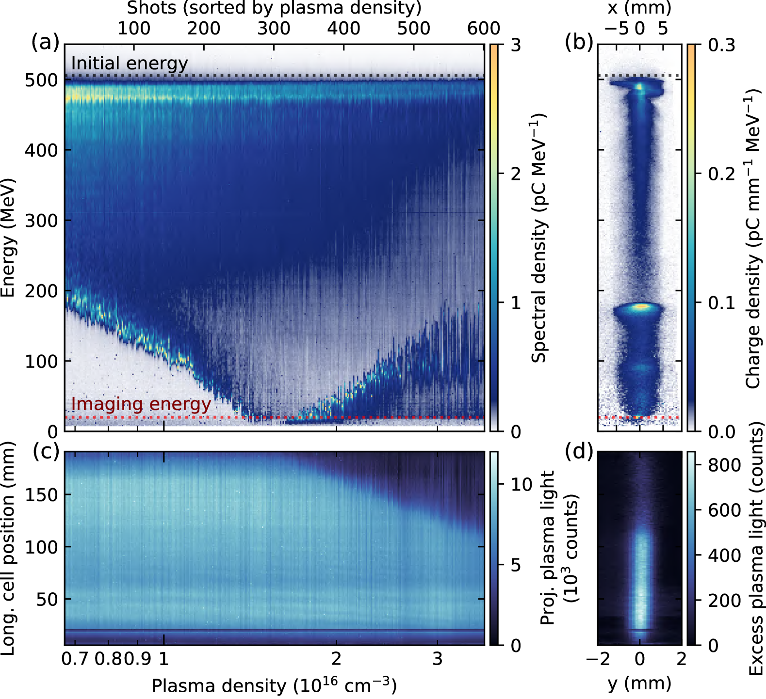
Experimentally, energy depletion has been demonstrated using a single drive beam (see Fig. 15), with driver-energy depletion efficiency exceeding 50% [387, 549]. Peña et al. [387] adjusted the depletion length to make it equal to the plasma length by varying the plasma density. As can be seen in Fig. 15(a), when the plasma density is increased, the maximum energy loss increases until the point where driver electrons reach a negligible energy. Increasing the plasma density further, re-accelerated driver electrons are observed with increasing energy, and the depletion length can be determined directly from the plasma light emission [see Fig. 15(c), where less energy is deposited in the plasma and less plasma light is detected after the depletion length] and is observed to decrease with the plasma density. The optimal plasma density corresponds to the highest density before re-acceleration is observed, i.e. when depletion occurs at the very end of the plasma accelerator.
II.3 Evolution of the trailing bunch
The goal of a plasma accelerator is typically to add energy to a particle bunch, and to do so compactly. However, energy gain and gradient are not the only requirements; high beam quality and energy efficiency may also be important, although which combination of these properties to optimize for will depend on the application (see Sec. V). For instance, a key metric in an FEL is the charge density in 6D phase space, the 6D brightness,
| (51) |
where is the bunch charge, is the normalized emittance in longitudinal phase space , while and are the emittances in the transverse phase spaces and , respectively. Another key metric, relevant to colliders, is the collision rate per energy spent, or more accurately the luminosity per wall-plug power
| (52) |
where is the wall-plug-to-trailing-bunch energy-transfer efficiency—itself the product of the efficiencies from wall-plug to driver , driver to plasma , and plasma to trailing bunch —and are the collision-point beta functions, which again set limits on through the bunch length and energy spread [408]. Delivering a high 6D brightness or luminosity per power at the end of the accelerator therefore requires understanding how the beam evolves in both the longitudinal (Sec. II.3.1) and transverse (Sec. II.3.2) phase spaces during acceleration. Finally, the spin polarization of the bunch can also be of relevance (Sec. II.3.3), especially for particle physics.
II.3.1 Longitudinal phase space
Beam loading and energy-transfer efficiency
When a trailing bunch is injected into the plasma wakefield excited by a driver in order to be accelerated, it modifies the wakefield by reducing its amplitude—a process referred to as beam loading. This process is most simply understood in the linear regime, where the principle of superposition applies: the total wakefield is the sum of the driver wakefield and the trailing-bunch wakefield [240]. Figure 16 shows an example of beam loading in the linear regime, with an electron driver and trailing bunch in a uniform plasma. The trailing bunch is located at the accelerating phase of the driver wakefield, adding its own wakefield contribution to it. Comparing Figs. 16(a) and (c), the wakefield is modified, or loaded, by the presence of the trailing bunch. Both within and behind the trailing bunch the amplitude of the plasma wakefield is smaller than that of the original driver wakefield: part of the plasma-wave energy has been extracted by the trailing bunch and converted to beam energy.
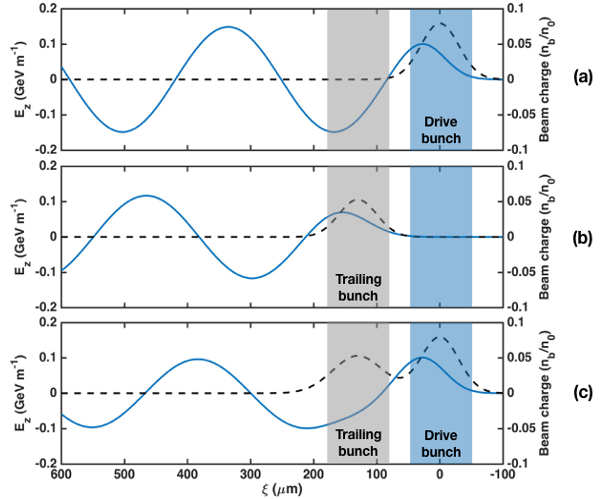
In the language of wave interference, the trailing-bunch acceleration can be understood as the destructive interference between the driver and trailing-bunch plasma waves. The case of perfectly destructive interference, where the total wave cancels in the wake of both beams, corresponds to an energy-transfer efficiency of 100%: all the energy in the plasma wave is being extracted by the trailing bunch, and no energy is left behind (with the caveat that the energy spread is also 100%). In contrast, if a beam is located at a position where the driver wakefield is decelerating, the constructive interference of plasma waves is in this case associated to beam deceleration—a phenomenon that can be leveraged to generate large amplitude plasma waves using multiple drive bunches [433] or multiple laser pulses [213, 96].
Destructive interference and beam acceleration provide two complementary pictures to understand energy transfer in this beam–plasma system. In the particle picture, the energy transferred by the driver to the plasma per unit propagation distance is simply proportional to the number of drive particles and the average electric field experienced by the driver . Similarly, the energy transferred from the plasma to the trailing bunch is proportional to its particle number and average field . The energy-transfer efficiency is defined as the ratio of the energy gained by the trailing bunch to the energy lost by the driver :
| (53) |
This can also be understood as the energy-transfer efficiency from the plasma to the trailing bunch, as is indeed the total energy that went into the plasma. It does not include the efficiency from the drive beam to the plasma (discussed in Sec. II.2.5), which is given by the ratio of the energy transferred to the plasma () to the total initial drive-beam energy.
In the wave picture, destructive interference reduces energy in the wave. The energy-transfer efficiency can thus be expressed as a ratio of wave energies, which in the linear regime can be expressed as [218]
| (54) |
where and are the amplitudes of the longitudinal () and transverse () components of the electric field of the drive-beam plasma wave, respectively, and are the amplitudes for the total plasma wave behind both beams, and the integral is performed over the transverse coordinates. The -field is zero behind the beams (see Sec. II.1.2), hence not contributing to . Consider the 1D case and the short-bunch limit where the driver (resp. trailing-bunch) density can be written as [resp. ], with and the surface number density of the driver and trailing bunch and and their longitudinal position: the total electric field obtained from Eq. (17) is given by
| (55) |
where and are the charges of the particles constituting the driver and trailing bunches, respectively. The efficiency can then be calculated using Eqs. (53) or (54) as a function of the numbers of drive and trailing particles and in a cross section . Importantly, must be equal to to ensure energy conservation for the beam–plasma system, so that Eqs. (53) and (54) provide the same answer—this result is known in accelerator physics as the “fundamental theorem of beam loading”, and, simply stated, tells us that a point particle experiences half of its own wakefield [433]. Assuming on-crest acceleration, for the same particle type (or equivalently for opposite particle type ), where is the plasma wavelength, the efficiency in the 1D linear regime is given by [240]
| (56) |
This efficiency expression also holds true in 3D when both the driver and trailing bunch have the same density profile. The more general case with different longitudinal and transverse profiles for each beam was discussed by Katsouleas et al. [240] and Hue et al. [218].
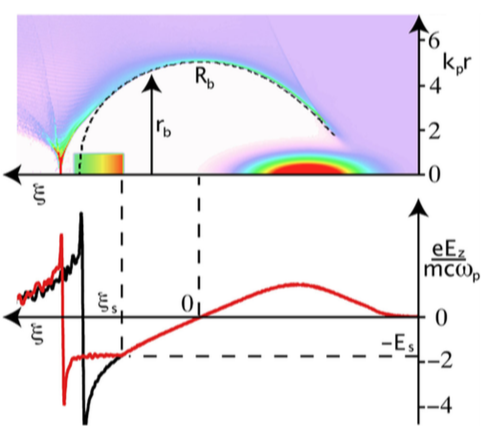
In the nonlinear regime, beam loading also describes how the wakefield is modified by the presence of the trailing bunch, but the principle of superposition does not hold. Yet, in the case of the blowout regime, which is particularly well suited for plasma-based electron acceleration, the use of the electron-sheath model [312, 313, 176] (see Sec. II.1.3) provides a simple description of beam loading: the trailing bunch modifies the trajectory of the plasma-electron sheath and thereby the longitudinal electric field [484] (see Fig. 17). To describe beam loading using Eq. (26), the normalized current term () needs to include both the driver and the trailing bunch: . The beam loading from the trailing electron bunch exerts a repulsive force on the electron sheath, causing it to move more slowly toward the axis, which again reduces the longitudinal electric field inside the wake.
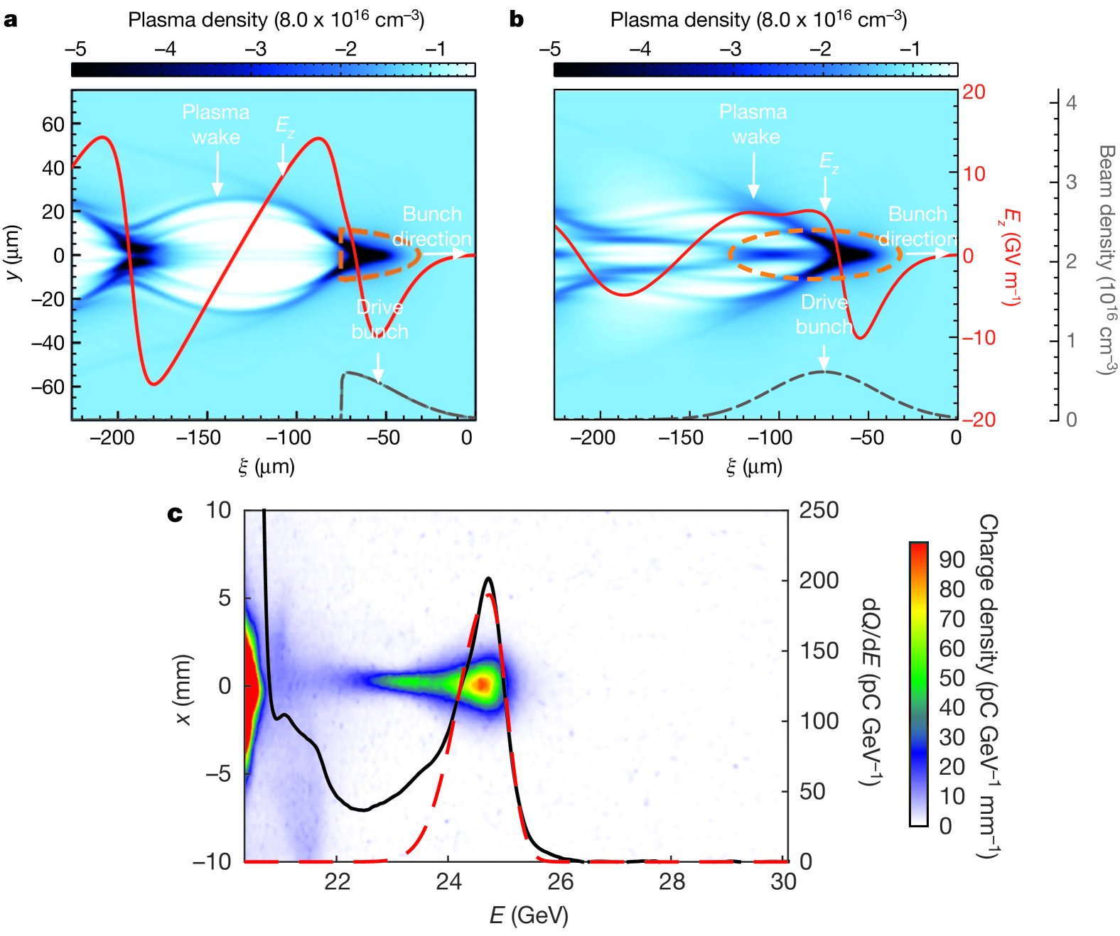
In contrast to the linear and blowout regimes, nonlinear beam loading with positively charged particles like positrons cannot be simplified to a wakefield superposition or a single electron-sheath trajectory. The nonlinear response of all plasma-electron trajectories to the beam load needs to be accounted for. This can be studied in simulations; an example of strong beam loading with a single positron bunch is shown in Fig. 18 [89]. The unloaded case [Fig. 18(a)], using a half-Gaussian positron bunch for which all positrons decelerate, has a plasma wake and on-axis electric field that resembles that of the blowout regime; the plasma electrons are sucked in by the positron bunch and then cross and overshoot the axis, thereby creating an ion cavity. In the loaded case, simulated in Fig. 18(b) using the full positron bunch, the rear half of the bunch experiences an accelerating field, thus extracting energy and loading the plasma wakefield. In this case, beam loading comes with a more profound change of the wakefield: in the presence of the rear half of the positron bunch, there is no longer an ion cavity free of plasma electrons. Instead, an on-axis plasma-electron filament provides a focusing force to the accelerated positrons, at a position where the transverse force was defocusing in the unloaded case. Positron beam loading can thus modify the transverse wakefield—a topic discussed more in Sec. III.1.
Optimal beam loading and energy spread
Due to the non-negligible bunch length compared to the plasma wavelength, the trailing bunch can occupy a large phase range and can thus see a commensurately large range of electric-field strengths. Figure 16 shows an example of beam loading in the linear regime, where the longitudinal electric field significantly varies over the length of the trailing bunch and therefore its particles do not gain the same amount of energy, resulting in a large final energy spread after acceleration in the plasma. The variation of within the trailing bunch is reduced due to beam loading, as observed by comparing Figs. 16(a) and (c), but it remains large. However, beam loading can be optimized to induce minimal energy spread. An optimal beam loading would be such that it results in a constant field along the full length of the trailing bunch. In the linear regime, optimal beam loading without any induced energy spread can be realized using a truncated triangular current profile for the trailing bunch, while a Gaussian bunch can provide an imperfect but reasonable optimization with some residual energy spread (see Fig. 19). Interestingly, while linear and nonlinear beam-loading models are completely different, in both cases can be flattened for a trailing bunch with a truncated triangular profile, as shown in Figs. 19(b) and 17, respectively. Gaussian beams can also provide reasonable flattening of in the nonlinear blowout regime.
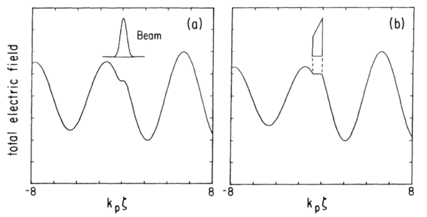
Beam loading is thus a key process that plays an important role in both energy efficiency and energy spread. Achieving simultaneously high energy-transfer efficiency and low energy spread was theoretically shown to be possible with optimal beam loading in the blowout regime [302, 484]. The first experimental observation of beam loading in the bubble/blowout regime was made in LWFA [413, 414], with a clear correlation between the trailing-bunch charge and the final beam energy. Further LWFA studies with high-charge bunches [92, 184] observed beam-loading signatures in the spectral shape and energy spread. In PWFA, evidence of beam loading in the blowout regime was reported by using distributed ionization injection [487] (see Sec. III.3.1), as well as by using a two-bunch configuration with drive and trailing bunches [292, 293] (see Fig. 41) where correlations between accelerated charge, final energy and energy spread of the trailing bunch were observed. More recently, a precise optimization of beam loading was demonstrated with a driver–trailing bunch configuration and allowed to flatten within the trailing bunch to an unprecedented precision [see Fig. 20 and Fig. 44(a)], with a residual field variation of only 2.8% rms [290]. In this optimal field-flattening condition, a high energy-transfer efficiency was measured, providing the first experimental evidence that beam loading in the blowout regime can simultaneously provide high efficiency and low energy spread.
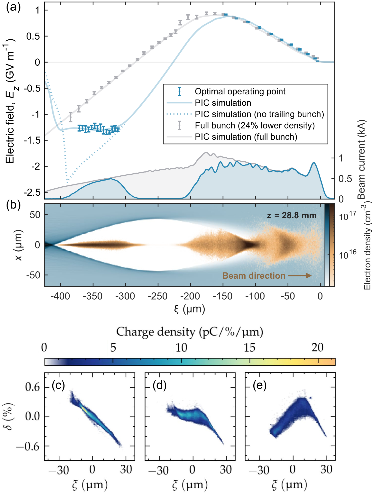
For positrons, the longitudinal electric field can also be flattened by nonlinear beam loading [see Figs. 18(b) and 26]. Using a single bunch, Corde et al. [89] observed the efficient acceleration of positrons located in the rear half of the bunch, and demonstrated that positron beam loading can result in a reduced peak accelerating electric field and a smaller energy spread for the accelerated positrons [see Fig. 18(c)]. Further evidence of positron beam loading in the nonlinear regime was obtained by Doche et al. [118] using a driver–trailing bunch configuration, observing the correlation between the trailing-bunch energy gain, energy spread and charge, as well as energy-transfer efficiencies of up to 40%.
While optimal beam loading can mitigate correlated energy spread (i.e., between longitudinal slices), plasma accelerators can also induce uncorrelated energy spread (i.e., within a longitudinal slice). According to the Panofsky-Wenzel theorem [Eq. (28)], if the focusing field changes longitudinally within the trailing bunch, as in the linear regime (see Fig. 6) and most positron acceleration schemes (see Fig. 26), the accelerating field will not be radially constant, causing an uncorrelated energy spread. Conversely, in the blowout regime, which has a longitudinally constant focusing field, the accelerating field is radially constant and thus preserves the uncorrelated energy spread—a major benefit of the blowout regime. This was verified indirectly by Clayton et al. [85], demonstrating that the focusing field was longitudinally constant, and later directly by González Caminal [179] by measuring the longitudinal phase space of plasma-accelerated beams [see Fig. 20(c–e)]. Lastly, note that the assumption of longitudinally constant focusing is broken in the case of ion motion (see Sec. II.3.2).
Dechirping
Flattening of the accelerating field of the wake via beam loading (see Sec. II.3.1 above) is the most elegant solution to mitigating the energy spread growth in a plasma accelerator. However, such beam loading requires precise shaping of the current profile of the trailing bunch, often necessitating multiple rf components, photocathode lasers or collimators [130, 297, 197, 443] to manipulate the longitudinal phase space of the beam sufficiently . If no remedial measures are taken, this will lead to a rapid build up of correlated energy spread, or chirp, in the trailing bunch, thus reducing its quality. This poses a problem also for internally injected bunches (see Sec. III.3), as their current profiles cannot easily match that required to flatten fully the longitudinal electric field at their trapping location. Furthermore, it may in fact be beneficial to allow the accumulation of a moderate chirp during acceleration as this may help suppress the beam-breakup instability [335] (see Sec. II.3.2). In this case, a dedicated module (or additional section in the accelerating module) would be required to remove the chirp after acceleration, as shown schematically in Figs. 21(a) and (b).
Modules for removing correlated energy spreads are commonplace in accelerator facilities, whereby the accelerating beam is placed in the first 90° of the rf phase in order to decelerate the higher-energy tail of the bunch. However, the dechirping strength of metallic cavities is limited by the same breakdown effects that also limit acceleration, which would therefore dominate the length of a plasma-accelerator linac. The same dechirping principle has been demonstrated in dielectric structures [19, 128] but the dechirping strengths were still below those required for application to a plasma accelerator. Plasma dechirpers were therefore developed [101, 532, 459], with the dechirping fields generated in plasma by an electron bunch produced and artificially chirped in an rf linac. Proof-of-principle results demonstrated dechirping strengths of [101], far exceeding those of competing state-of-the-art techniques. In these first results, the correlated energy spread of the incoming electron bunch was reduced by a factor of 3–6 to the sub-percent level [see Fig. 21(c)] required for application to photon science and high-energy physics (see Sec. V).
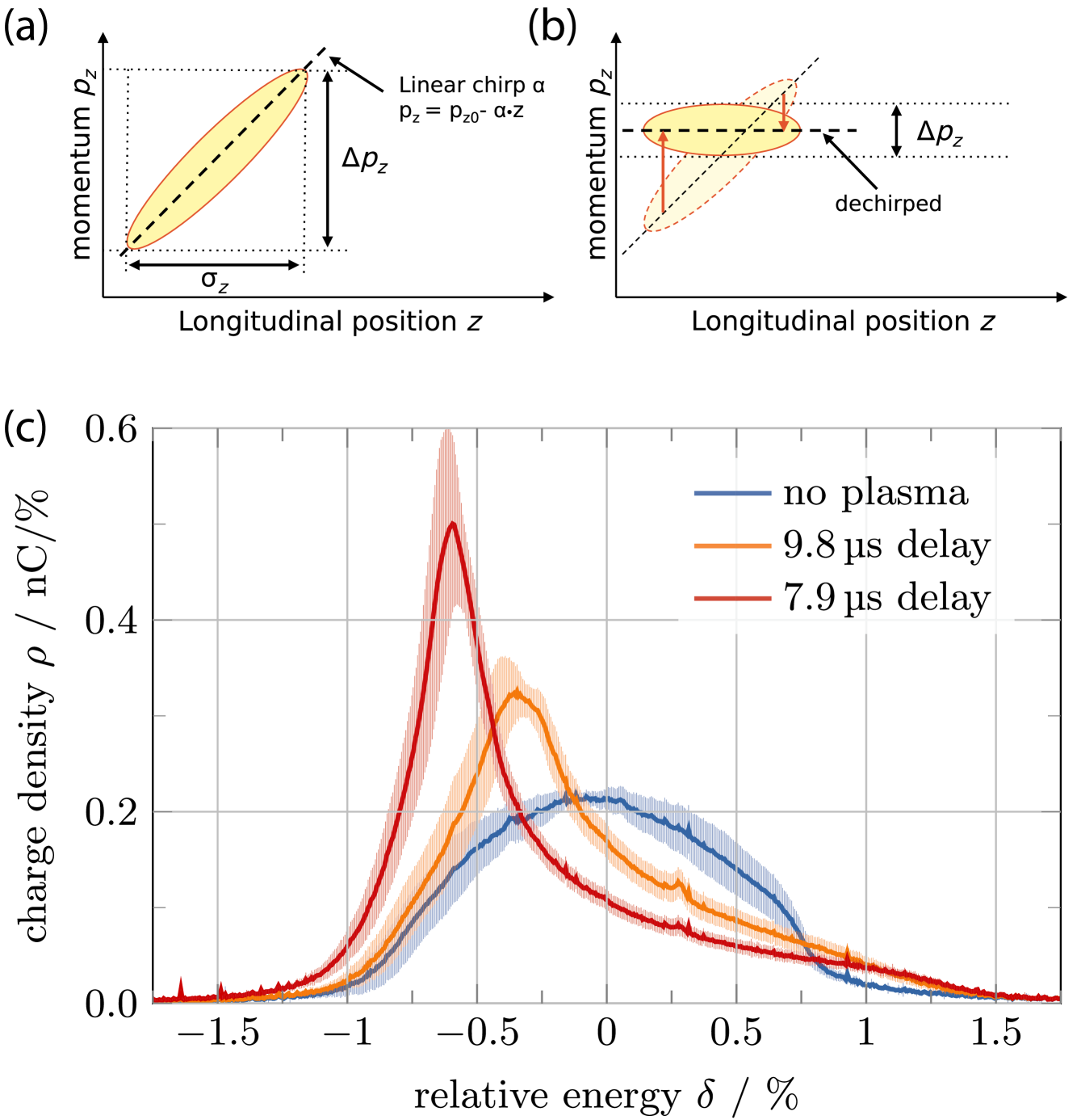
In the aforementioned proof-of-principle demonstrations, the dechirped beam was the same as that used to produce the dechirping fields. This has inherent downsides, as the bunch will experience some level of head erosion (see Sec. II.2.2) and thus emittance growth. Plasma dechirpers can be modified in two ways to mitigate this effect: (1) the on-axis focusing can be removed by using a hollow-channel plasma (see Secs. II.1.5 and III.1.2). Such a hollow-channel dechirper [533] was recently demonstrated experimentally, reducing the full-width at half-maximum (FWHM) energy spread from 0.93% to 0.11% [294]. Alternatively, (2) emittance growth is avoided by using a separate leading wakefield driver. One option is to use a laser driver to generate the wake, placing the trailing bunch at the zero crossing of the longitudinal wakefield: this so-called active plasma dechirper has been shown in simulation to dechirp the trailing bunch and reduce its energy spread by an order of magnitude [146]. Note that this scheme will remove a chirp of opposite sign to that of the passive dechirper. A similar effect is achieved by using an electron driver, as recently demonstrated in a combined plasma accelerator and dechirper [400], halving the energy spread from 0.2% to 0.1% rms while accelerating by .
More exotic schemes have also been proposed. This includes allowing a trailing bunch accelerating in a PWFA to accumulate chirp over a certain fraction of the acceleration length. Then, an additional escort bunch is internally injected from the quiescent plasma background (see Sec. III.3) to overload the wakefield in the location of the trailing bunch: this adds a chirp of opposite sign, effectively removing the initially accumulated chirp [316]. Finally, the chirp can also be mitigated during acceleration by applying a periodically modulated plasma density [56].
Dephasing and bunch length
The slippage of the trailing bunch with respect to the plasma wave, referred to as dephasing, is a major limitation for LWFA due to the sub-luminal laser group velocity in the plasma [132]. In most electron- and positron-driven PWFA scenarios, dephasing is completely avoided, because both the driver and trailing bunch essentially propagate at the speed of light. Indeed, when the plasma wave has a phase velocity determined by that of the driver and if the Lorentz factor of the trailing bunch is much larger than that of the driver , then the trailing bunch slips by a distance for a propagation distance . For instance, it corresponds to a negligible trailing-bunch slippage of the order of per meter of propagation for a electron driver. Dephasing in PWFA is thus only important when the plasma-wave phase velocity differs from the drive-beam velocity, which is possible in plasma-density ramps (as used in the downramp internal-injection scheme discussed in Sec. III.3) and for strongly evolving drivers where the plasma wavelength effectively varies during the propagation (see Sec. II.2). Dephasing also occurs when the plasma wave is associated with a growing instability, such as in self-modulated plasma wakefields (see Sec. III.2). The phase velocity of self-modulated wakefields [Eq. (75)] can be substantially smaller than and dephasing needs to be addressed. Moreover, dephasing can be significant for short proton drivers (i.e., not relying on self-modulation) [66], given the much smaller , but this effect can be mitigated by a gradual plasma-density upramp [237, 405].
The bunch length is typically preserved inside a plasma accelerator, as the particles dephase negligibly with respect to each other. In practice, however, the bunch can be shortened by charge loss from the tail of the trailing bunch [290], either from defocusing by the sheath electrons or from deflection by instabilities (see Sec. II.3.2). Lastly, if using multiple stages separated by optics with longitudinal dispersion (), the bunch length and phase can evolve through a self-correction mechanism (see Sec. III.5 and Fig. 37).
II.3.2 Transverse phase space and emittance
Emittance is a key parameter for applications of PWFA, directly affecting the brightness in FELs [Eq. (51)] and luminosity in colliders [Eq. (52)]. In simple terms, it quantifies the ability of a beam to be focused to a small transverse size—the smaller the emittance, the smaller the beam size in a focus. Specifically, the normalized emittance quantifies the area of the rms ellipse of the particle distribution in transverse phase space [153], as defined in Eq. (40). In a vacuum or in a linear focusing field, this normalized emittance is preserved during acceleration. While the emittance cannot decrease, unless the beam is undergoing radiative damping (see Sec. II.3.2), there are numerous ways for the emittance to increase (covered in Secs. II.3.2–II.3.2). Preserving the emittance is therefore a challenge in a plasma accelerator—a topic reviewed in more detail by Lindstrøm and Thévenet [287].
Emittance measurements were first performed on internally injected bunches from laser-driven plasma accelerators, using a variety of measurement techniques: the “pepper-pot” method [159, 57]; the multi-shot quadrupole scan and the single-shot “butterfly” method [521, 29]; and betatron x-ray spectroscopy [249, 393, 97]. These methods were later applied to both internally and externally injected bunches from beam-driven plasma accelerators, including the butterfly method [488] and quadrupole scans [460], with plans for also using betatron radiation [436]. The first experimental demonstration of emittance preservation, with moderate energy gain, was performed by Lindstrøm et al. [291] using quadrupole scans [see Fig. 44(b)]. Simultaneous emittance preservation and large energy gain—the ultimate goal of several PWFA facilities [233, 100, 194]—has been shown in simulations [551], but has not yet been shown in experiments.
Mismatching
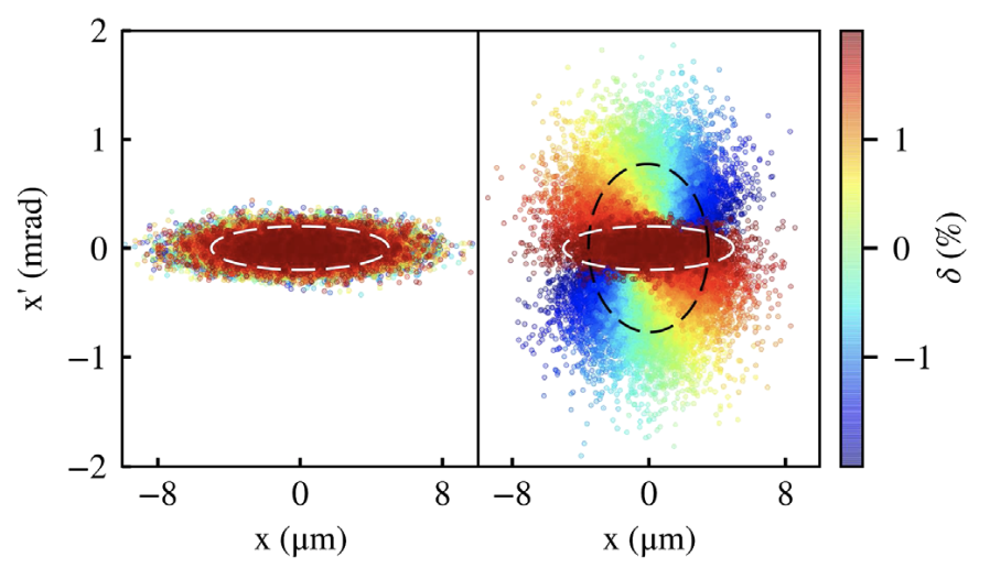
Within a plasma accelerator, the ion column focuses the particles, causing them to rotate along an ellipse in phase space. If the phase-space distribution of the beam is matched, such that the beta function is [Eq. (43); assuming the blowout regime], then the beam size and divergence remain constant (ignoring acceleration). However, if the beta function differs from , it will oscillate as the beam propagates. This can be quantified with the mismatch parameter [438]
| (57) |
where , and each quantify the mismatch in the individual Twiss parameters. A mismatch is problematic if the beam has a finite energy spread, as particles of different energy will oscillate at different rates, causing them to spread out over a larger area in phase space—increasing the projected emittance (see Fig. 22). The emittance steadily increases until the different energy slices have fully decohered, resulting in a relative emittance growth
| (58) |
where and are the initial and saturated emittances, respectively. Matching to a longitudinally flattop plasma-density profile, for which , this equation simplifies to [332]
| (59) |
Full decoherence occurs at an approximate distance
| (60) |
where is the relative energy spread; this decoherence length corresponds to oscillations of the beta function, or betatron wavelengths.
Reaching the often small beta functions required for matching can be challenging in practice. As an example, at a plasma density of and energy , the beta function is , which is much smaller than that commonly seen in rf accelerators. To mitigate this, longitudinal plasma-density ramps [321, 538, 20] can be used to increase the matched beta function at the entrance and exit of the plasma accelerator, while leaving the density and accelerating gradient in the interior unchanged. Slowly varying adiabatic ramps [75] are particularly well suited for preserving emittance. However, for positrons focused by an on-axis electron filament (see Sec. III.1.1) ramps can be detrimental [511].
Misalignment
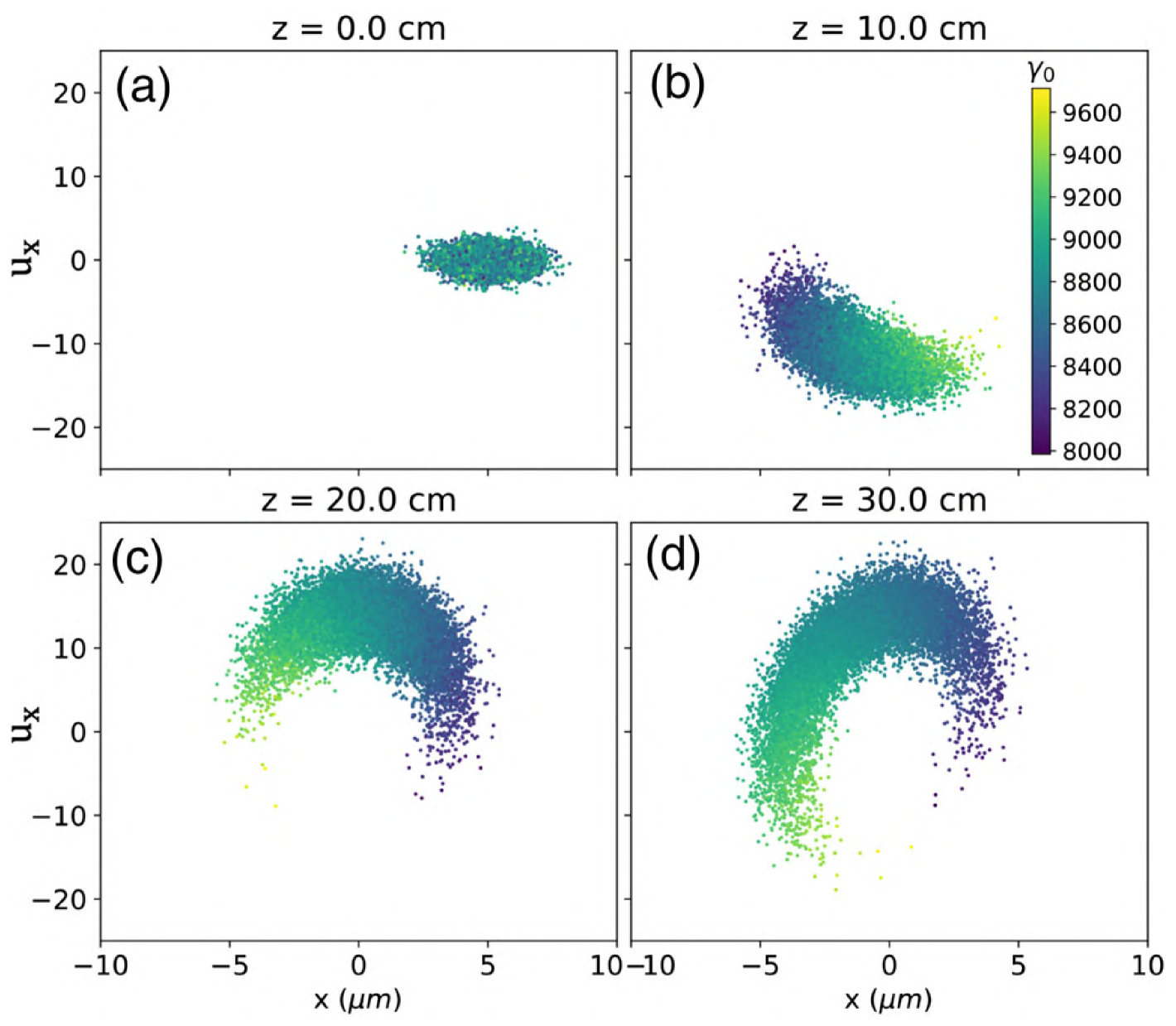
Misalignment of the bunch centroid can also lead to emittance growth, for the same reason as when the beam is mismatched: particles of different energy rotate in phase space at different rates, leading to phase mixing (see Fig. 23). Both positional and angular misalignments, and , will contribute to an emittance that grows over the decoherence length [Eq. (60)] to saturate at [285]
| (61) |
added in quadrature with the initial emittance. More detailed expressions are required when large energy change occurs during the decoherence [474].
Suppressing this emittance growth imposes strict tolerances on alignment [22, 77, 452]. Consider for instance a collider-like beam at and a plasma density of ; to stay below , the bunch must be aligned to within or . This conclusion is complicated somewhat when using multiple stages [77]: if each stage is short enough to not allow full decoherence and misalignments are uncorrelated, the final emittance scales as where represents the final energy and is the number of stages [285]. Use of plasma-density ramps can loosen the tolerances of the positional misalignment, but will simultaneously tighten the angular misalignment tolerance [as seen in Eq. (61)]. Ultimately, beam alignment will pose a significant challenge to any high-beam-quality PWFA facility, likely favoring reduced plasma densities (to below ).
Beam-breakup instability
The hosing instability [525] is often considered to affect the driver (see Sec. II.2.3), but the same effect applies to the trailing bunch. In rf accelerators, the effect is known as the beam-breakup instability [382]. When the trailing bunch is transversely offset, it will repel the plasma-sheath electrons closest to it a bit more strongly and those farthest from it a bit more weakly; this deforms the plasma cavity behind that point, shifting the focusing axis, and leading to a positive feedback loop with increasing oscillation amplitudes. For this reason, stronger beam loading of the wakefield (giving higher energy-transfer efficiency) will result in a stronger transverse instability. Lebedev et al. [266] postulated a fundamental efficiency–instability relation:
| (62) |
where is the ratio of the transverse wakefield per offset to the focusing strength (i.e., force per charge per offset), and is the energy-transfer efficiency (plasma wake to trailing bunch). The oscillation amplitude increases exponentially with the product [266], where is the integrated phase advance, leading to emittance growth via Eq. (61). This implies that large energy gain and high efficiency can be problematic. More detailed studies using PIC simulations indicate that Eq. (62) is in fact the best-case scenario [152], assuming zero energy spread and immobile ions. No experiments have yet conclusively observed the beam-breakup instability, although attempts have been made [5].
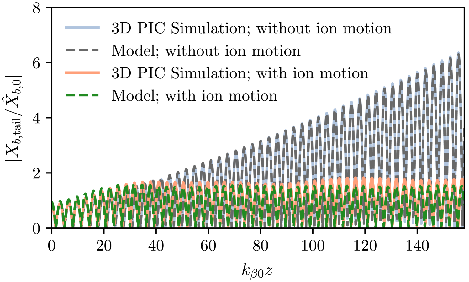
The assumptions of no energy spread or ion motion are, however, unrealistic in plasma accelerators. Taking these effects into account allows the instability to be suppressed: the oscillation of different longitudinal slices can be detuned either by imposing an energy chirp on the trailing bunch, so-called BNS damping [26, 334] or by allowing ions to move slightly, the focusing strength can increase longitudinally along the bunch [333] (see Fig. 24).
Ion motion and nonlinear focusing fields
Just as the ions of the plasma cavity focus the accelerating electron beam, the electron beam focuses the ions. Within a long, uniform electron beam, ions will oscillate with a frequency , where and are the beam and plasma densities, and and are the ion and electron masses. These oscillations typically occur on a much longer timescale [e.g., nanosecond scale [102]] than that of the plasma-electron frequency (i.e., the sub-picosecond scale). However, for a sufficiently dense beam, , ion motion can occur within the beam itself [267]—relevant for the high beam densities of collider beams. In this case, a density spike forms on axis with strongly nonlinear focusing forces (see Fig. 25). The spike forms when the phase advance of the ion oscillation within the bunch [429]
| (63) |
exceeds a quarter oscillation; . Here, , , and are the length, number of particles, relativistic factor and emittances of the trailing bunch, respectively, is the ionization state of the ions (e.g., when singly ionized), and is the classical electron radius.
The resulting nonlinear focusing can cause catastrophic emittance growth. However, the emittance only grows until a non-Gaussian equilibrium distribution [306] is reached. This implies that over-focused beams will result in less emittance growth [15], and that full emittance preservation can be achieved by directly matching to the equilibrium distribution [41]. Such injection is technically challenging using an rf accelerator, but can instead be accomplished by gradually increasing the ion motion: either with an ion-mass ramp from heavy to light ions [171], or by adiabatic damping [39], where the beam density increases with acceleration. While ion motion is suppressed in heavier gases, this can itself cause emittance growth from increased Coulomb scattering (see Sec. II.3.2). Note also that at sufficiently high ion temperatures, of order 10– (unlikely to be reached even during high-repetition-rate operation), ion motion is suppressed as the ion spike smears out [170].
For flat beams, as employed in linear colliders, where the emittance is much larger in one transverse plane compared to the other, resonant emittance mixing can occur [113]. As a result, the emittance increases in the low-emittance plane, and decreases in the high-emittance plane. This happens even when ion motion is suppressed (i.e., for weakly nonlinear focusing), but then only over a large number of betatron oscillations. The resonance can be suppressed if the focusing is stronger in the low-emittance plane, which can be achieved using drive bunches flat in the orthogonal direction; i.e. a vertically flat driver when the trailing bunch is horizontally flat and vice versa.
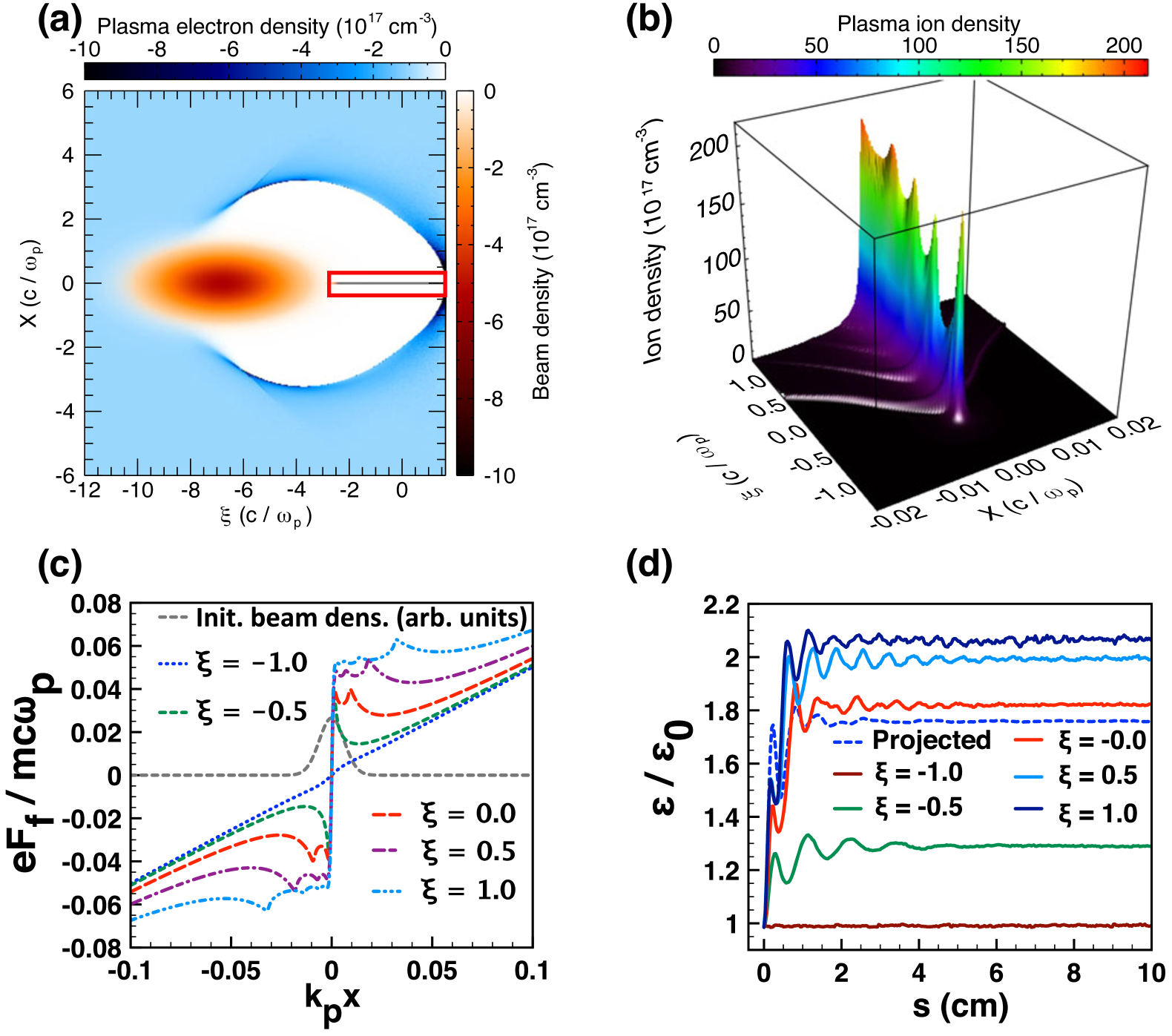
While the above discussion applies to electron bunches, the same challenge arises for positron bunches (see Sec. III.1), where the equivalent problem of electron motion similarly results in emittance growth, but at much lower beam densities. Lastly, ion motion can also occur within the self-modulated wakefields of a long proton bunch [503] (see Sec. III.2), as recently observed at the AWAKE experiment [483].
Coulomb scattering
The presence of matter on the beam axis is unavoidable in plasma accelerators, and can lead to beam particles scattering off gas particles or ions, known as Coulomb scattering [45, 44]. While a small fraction of particles will scatter inelastically off the atomic nucleus, causing particle loss or a beam halo, most particles scatter elastically at a small angle. Multiple such scattering events will increase the rms divergence and, correspondingly, increase the emittance [411].
The emittance growth per length has contributions from both gas particles and ions [245]:
| (64) |
where is the beam’s beta function and is the relativistic Lorentz factor. The gas-scattering term [43] is given by
| (65) |
where is the gas number density, indicating that gas scattering increases quadratically with the atomic number . Note that Eq. (65) is accurate to 11% or better for interaction lengths between and radiation lengths, but only applies when multiple scattering events occur. Next, the ion-scattering term [342], verified with simulations [550], is given by
| (66) |
where is the ion density, and the (Coulomb) logarithm contains the ratio of the maximum and minimum impact parameters—estimated to be (the Debye length) and fm (the atomic radius), with the atomic mass number. In a non-quasi-neutral plasma, such as in the ion column of a blowout, the maximum impact parameter increases to be approximately the blowout radius [245].
Integrating Eq. (64) over the acceleration length, and assuming that the beam is matched, the cumulative emittance growth scales as [245], where is the total phase advance. Assuming a constant normalized accelerating gradient , this emittance growth is independent of plasma density, because higher density allows smaller beta functions and shorter acceleration distance. The main strategy for suppressing Coulomb scattering is therefore the use of lighter gas species. Ultimately, Coulomb scattering can be made negligible with hydrogen, with an expected emittance growth for a TeV collider of only around [449].
Radiative damping
Particles that oscillate transversely in a focusing field will emit synchrotron radiation [133], thereby losing momentum in the direction of emission—the so-called radiation reaction. If the particle is subsequently accelerated in the forward direction, the net effect can be a radiative damping of the transverse emittance. This is the concept behind damping rings, but is normally ignored in rf linacs due to the short acceleration length. However, in the presence of very strong focusing fields, as in a PWFA, the effect can be non-negligible [337]. Each particle evolves according to a coupled set of equations for the transverse positions , and the Lorentz factor
| (67) | |||
| (68) | |||
| (69) |
where and for a blowout. Here, we assume no coherent radiation and no interaction between the particles and the emitted radiation. For very high plasma densities or energies, the dynamics can also be affected by strong-field QED effects [545, 178]. From Eq. (69), we see that the effect of the radiation reaction is most significant in the longitudinal plane, acting as a deceleration term that scales quadratically with energy. In a bunch with finite emittance, particles oscillate with a range of different transverse amplitudes, which can therefore introduce an energy spread. Assuming no centroid offsets, radiative damping does not impose a fundamental limit on the achievable energy in plasma-based accelerators [108], as the radiative damping of emittance sufficiently reduces the oscillation amplitude during acceleration; the damping force approaches of the accelerating force [253]. However, with imperfect alignment the achievable energy will be limited—typically around the TeV range for offsets and densities [434], or alternatively placing an upper bound on the plasma density given a certain alignment tolerance.
II.3.3 Spin polarization
Spin polarization is a beam quality that is important for certain applications, in particular for nuclear and particle physics [174, 458]. It is defined as
| (70) |
where is the unit spin vector for each of the particles. Typically, a polarization of –80% is required in a linear collider [343], which implies that a high polarization is required at the source, and must be maintained throughout acceleration.
Spin-polarized electrons are conventionally produced in negative-electron-affinity GaAs photocathodes [392], whereas polarized positrons are made with either circularly polarized photons [373, 419] or using polarized electrons [1]. High-energy storage rings will also polarize beams through the Sokolov-Ternov effect [464]. More compact methods of producing polarized electron bunches in a plasma accelerator have been proposed, either using laser drivers [522, 530, 529, 138, 50] or beam drivers [531, 363, 364]. Here, plasma electrons are injected directly into a wake driven in a pre-polarized plasma, made e.g. by photodissociating hydrogen halides with a UV laser [409].
After generation, the particle spins can evolve during the acceleration process—a topic reviewed in detail by Mane, Shatunov, and Yokoya [317]. Three effects must be taken into account [476]: the Stern-Gerlach force, which separates the orbits of opposite spins (relevant at low energy); the Sokolov-Ternov effect, whereby the radiation reaction depends on the spin (relevant at high energy and over long timescales; see Sec. II.3.2); and spin precession in magnetic fields, described by the T-BMT equation, named after Thomas [477] and Bargmann, Michel, and Telegdi [30]:
| (71) |
where the numerical factors for each frequency term are
| (72) |
Here, is the anomalous magnetic moment of the particle ( for electrons), and are the particle’s velocity and Lorentz factor, respectively, and and are the electromagnetic fields it experiences. The strong fields of the plasma wake can therefore lead to spin precession, and if the fields vary sufficiently across the bunch, it can be depolarized. However, if the emittance is sufficiently small, the polarization can be preserved during acceleration [505], requiring that
| (73) |
where is the plasma density, is the initial beam energy, is the transverse beam size, and quantifies the strength of the focusing force ( in a blowout). It is currently unclear whether spin polarization can be preserved across multiple stages—this will depend on the beam transport optics between the stages (see Sec. III.5).
III Advanced topics
Several aspects of beam-driven plasma acceleration go beyond the simple picture of a driver, a wakefield and a trailing electron bunch. These topics include positron acceleration (Sec. III.1), proton drivers and self-modulated wakefields (Sec. III.2), internal injection (Sec. III.3), long-term evolution (Sec. III.4) and staging (Sec. III.5).
III.1 Positron acceleration
Acceleration of positrons in plasmas is motivated by the need for more compact electron–positron colliders (see Sec. V.1). As an accelerating medium, plasmas are unique in that their nonlinear response to beams of opposite charge is asymmetric (see Sec. II.1.3 and Fig. 7). This is because plasmas are composed of light, mobile electrons, and heavy, effectively immobile ions. The structure of the wakefield is determined by the motion of the plasma electrons, with the plasma ions acting as a stationary background. As a result, while the standard blowout regime accelerating the trailing bunch in an ion cavity is particularly favorable for electron acceleration, it is hardly suited for positron acceleration. Indeed, the transverse fields are defocusing inside the ion cavity, and the region where the fields are focusing and accelerating is where plasma electrons cross the propagation axis [303], which is extremely narrow with very nonuniform fields unless beam loading (see Sec. II.3.1) or some specific shaping of the beam or the plasma (or both) is employed.
The challenge for positron acceleration in plasmas, a topic reviewed in detail by Cao et al. [70], is twofold: (i) to excite a wakefield that provides an optimal region that is simultaneously accelerating and focusing (Sec. III.1.1), or oppositely that is free of any plasma focusing (Sec. III.1.2); and (ii) to load the wakefield with reasonable charge and energy efficiency without compromising beam quality or becoming unstable. An additional challenge is access to positrons: as an alternative, in-situ generation and injection of positron bunches has been proposed (Sec. III.1.3).
III.1.1 With plasma focusing
In this section, we consider positron-acceleration schemes that use on-axis plasma electrons for focusing, either unloaded (Sec. III.1.1) or loaded (Sec. III.1.1), as well as schemes that require more complex beam and/or plasma shaping (Sec. III.1.1).
Unloaded positron acceleration
The first question to address is how to excite a wakefield with a sizeable volume that is simultaneously focusing and accelerating for positrons. One suggestion is to rely on the linear regime (see Sec. II.1.2) where the drive beam causes only a small perturbation to the plasma-electron density and for which the plasma response is symmetric to beams of opposite charge. The linear wakefield has one quarter of the plasma wave period that is focusing and accelerating for positrons, which is thus appropriate in the unloaded case where the positron beam has negligible influence on the plasma wakefield. The demonstration of positron focusing in the linear regime was in fact the first experiment involving positrons in plasmas [362].
In the unloaded case, the energy spread cannot be optimized with beam loading (see Sec. II.3.1), but the use of a modulated plasma density—alternating between focusing and defocusing and between positive and negative slope for the accelerating field—can mitigate the accumulation of energy chirp in the plasma and thus reduce the final energy spread [56]. This latter simulation result, with pC-level charge, preserved -level emittance and 0.24% final energy spread, was demonstrated for electrons but is also applicable to positrons by virtue of the symmetry of the linear regime. It was also found that plasma wakefields linearly driven by electron beams can be used to accelerate positron beams with a density exceeding that of the plasma without compromising beam quality [218]. In the unloaded limit, such an approach is however limited to low charge and low efficiency from plasma to positron beam, and because it is also very challenging to achieve a stable driver propagation all the way to depletion in the linear regime [216], it is not the regime best suited for high driver-to-plasma efficiency (see Sec. II.2.5).
Experimentally, for beam densities exceeding that of the plasma, positron acceleration was observed in an unloaded, nonlinear and nonrelativistic (see Sec. II.1.3) plasma wakefield using a single bunch [46]. Although the beam was successfully transported through the plasma [210], the beam–plasma interaction resulted in a degraded quality [353]. In this experiment, positrons at the bunch tail were accelerated with a broadband spectrum and with a maximum unloaded gradient of , which was limited at the time by the rms bunch length and associated low plasma density () and low beam current [, as defined in Eq. (22)].
There are several other schemes (covered in Sec. III.1.1) that can generate a sizable volume simultaneously focusing and accelerating for positrons and that are generally well suited for unloaded positron acceleration. For example, for the electron-driven blowout regime, the narrow focusing and accelerating region around the sheath electron crossing point can be considerably extended by the use of a plasma column whose radius is slightly smaller than the blowout radius [116], or by the use of an escort electron bunch loading the back of the blowout and resulting in an elongated cavity [514]. In the unloaded limit, this elongated cavity has been shown to accelerate positrons with preserved emittance.
Loaded positron acceleration
Energy efficiency and charge are generally important when considering positron acceleration, as these are required for high luminosity per power [Eq. (52)] in colliders (see Sec. V.1). However, unloaded positron acceleration has low energy efficiency and is unable to accelerate high charge. Therefore, understanding the physics of positron-loaded plasma wakefields is crucial to model properly plasma-based positron accelerators and assess their performance.
As for electrons, positron beam loading modifies the longitudinal profile of the accelerating field , as discussed in Sec. II.3.1. Such longitudinal positron beam loading was shown experimentally by the correlation between energy gain, energy spread and positron charge in the two-bunch positron experiment of Doche et al. [118], which successfully accelerated distinct positron bunches in loaded plasma wakefields spanning linear to nonlinear regimes. In the single-bunch experiment of Corde et al. [89], a flattening of in the second half of the bunch resulted in a low-energy-spread accelerated peak in the positron spectrum [see Figs. 18(b–c)]. The nonlinear plasma wakefield, excited by the front half of the bunch, was thus self-loaded by the rear half of the bunch. With a bunch length in the range 30–, the beam current was much higher than in previous experiments, moving from the nonrelativistic () to the relativistic regime () and achieving a loaded accelerating gradient of in a plasma of density [89]. A similar flattening of with a positron load located just behind the first blowout cavity (see Fig. 26) was shown to be possible in an electron-driven blowout wake [553].
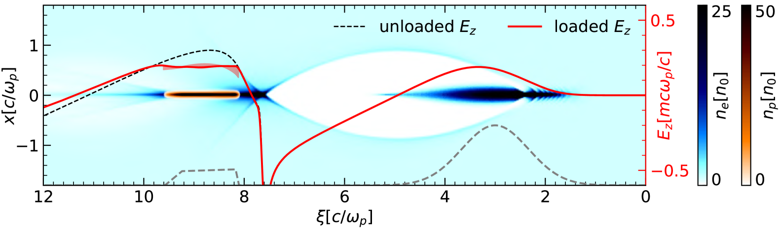
Contrary to electron beam loading in the blowout regime, positron beam loading also has a strong influence on the transverse fields because of the high mobility of the plasma electrons flowing through the positron bunch. These plasma electrons, necessary to provide plasma focusing, have a role that is analogous to the ion motion (discussed in Sec. II.3.2) for electron acceleration, except that their detrimental effect appears at much lower beam density because [see the role of in the phase advance of Eq. (63)]. Electron motion induced by the positron load within the bunch itself is in fact the key challenge that can limit the performance of positron acceleration when relying on plasma focusing. Positron beam loading can also have benefits, e.g., its ability to modify also the transverse fields can turn a defocusing region (when unloaded) into a focusing region (when loaded) favorable for positron acceleration. This transverse beam-loading process, central to the experimental demonstration of positron acceleration in a self-loaded plasma wakefield [89] (Fig. 18), opens the way to accelerating positrons in a loaded electron-driven blowout wake [553], something thought to be impossible when only considering the unloaded wake. This new path relies on an on-axis electron filament formed and maintained by the positron load, thus providing a region of the loaded wake that is simultaneously focusing and accelerating for positrons—a region that did not exist in the unloaded wake.
As we push the performance of positron acceleration towards higher charge and higher efficiency, the positron load is increased, which enhances electron motion within the bunch and can compromise the beam quality. Such electron motion typically leads to nonuniform charge and current density, and thus to a radially nonlinear and slice-dependent transverse force. By virtue of the Panofsky-Wenzel theorem [Eq. (28)] [383], this also translates to a radially dependent accelerating field. This radially nonlinear and slice-dependent transverse force impacts emittance, although it is generally possible to mitigate emittance growth by quasi-matching or slice-by-slice matching the beam to be as close as possible to a self-consistent radial equilibrium [41, 110, 218]. The radially dependent accelerating field impacts the uncorrelated energy spread, as positrons located at different radial positions do not experience the same accelerating field (see Sec. II.3.1). When increasing the positron load, the uncorrelated energy spread can easily exceed 1%, and as a result a trade-off between energy efficiency and beam quality needs to be found [218]. It has been shown that for -level emittances, linear, moderately nonlinear with –2 [218] and strongly nonlinear regimes with [553] can reach tens-of-percent energy-transfer efficiencies with percent-level uncorrelated energy spread and limited emittance growth. Higher nonlinearity allows for higher accelerating gradient and higher positron charge. In Zhou et al. [553], a model for nonlinear positron beam loading was used to guide the optimization of the positron current profile and flatten (see Fig. 26), resulting in a total energy spread (correlated and uncorrelated) of about 2% rms.
Beam and plasma shaping
A natural strategy to find new schemes with conditions appropriate for positron acceleration is to shape the beam, the plasma or both. These schemes are typically designed to provide focusing and acceleration for positrons, and can be optimized to tolerate a substantial positron load. An exhaustive review of positron-acceleration schemes [543, 502, 222, 116, 462, 463, 514, 554, 415] can be found in Cao et al. [70], who identified three main directions with the potential to reach a reasonable luminosity per power [see Eq. (52)]: (i) using donut-shaped drivers, (ii) finite-radius plasma columns, and (iii) asymmetric drivers in hollow channels.
Donut-shaped drivers offer a straightforward way to provide plasma electrons on axis for focusing, while being operable in the strongly nonlinear regime. Indeed, whether the donut-shaped driver is a laser [502, 336, 516, 543], an electron beam [222, 507, 221] or a non-neutral “fireball” (i.e., electron–positron beam) [463], the key principle is that inner plasma electrons are pushed inward or guided through the hollow core of the donut, forming a population used for the focusing of the positron bunch. Outer plasma electrons are pushed away and are then pulled back by the ions, forming a structure similar to the blowout regime, except for the presence of plasma electrons near the axis. The motion of these outer plasma electrons is responsible for the generation of the accelerating field. This donut-shaped driver regime thus benefits from the decoupling of focusing and acceleration, which are handled by two distinct populations of plasma electrons. By operating in the strongly nonlinear regime, high positron charge () can be accelerated at very high gradient (), although with limited energy-transfer efficiency () [218, 70]. One important challenge lies in the propagation of the donut driver, to ensure it maintains its shape with a stable wakefield until its depletion, without being prone to filamentation instabilities or to on-axis collapse [468, 384, 221].
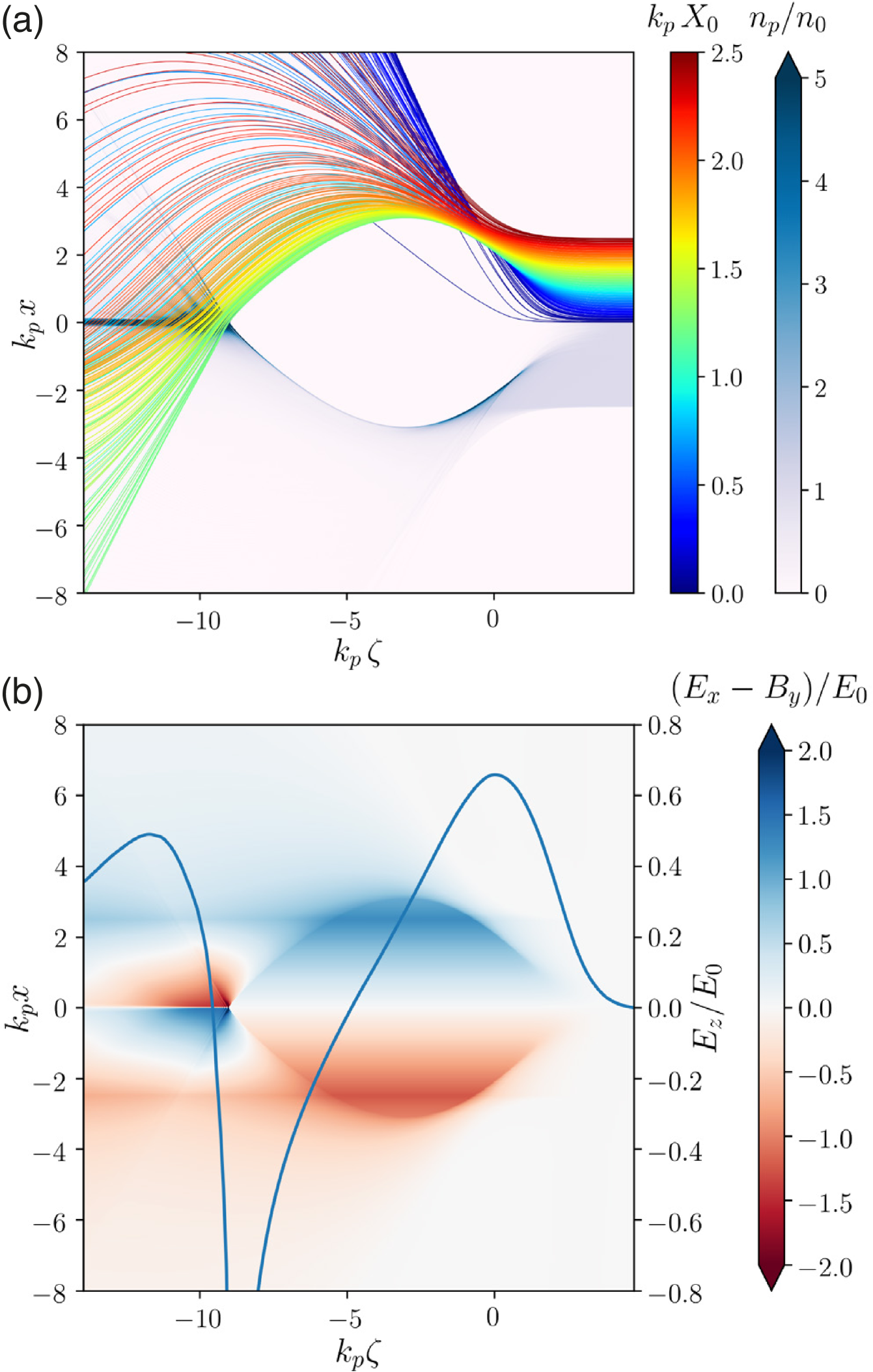
Another strategy is to modify the plasma shape to a finite-radius plasma column (surrounded by neutral gas in practice), whose radius is slightly smaller than the blowout radius, . This leads to a focusing force decreasing with outside the plasma column. Plasma electrons, which usually circulate in a thin sheath around the blowout cavity and cross the axis in a narrow region at the rear of this cavity, now follow different trajectories due to this decreasing focusing force for . As a result, these plasma electrons cross the axis at different longitudinal positions [see Fig. 27(a)]. This decoherence of plasma electron trajectories and spreading of their crossing positions is the key principle behind the finite-radius plasma-column scheme [116], making it possible to have an on-axis filament of plasma electrons providing focusing for positrons over a wide region where is accelerating, as shown in Fig. 27(b) for . This scheme can accelerate a positron charge of about with high quality ( preserved emittance, energy spread) and at high gradient () [110], as well as with a stable propagation for both the drive and trailing bunches [115, 111]. A non-zero plasma temperature can also help in preserving beam quality, by radially broadening the plasma electron filament and improving the radial uniformity of the accelerating field [112]. Importantly, because the focusing of different positron slices is provided by different plasma electrons, the limit of electron motion (analog to ion motion in electron acceleration) discussed in Sec. III.1.1 can be overcome. Indeed, here plasma electrons do not flow longitudinally through the entire positron bunch, but cross through it transversely [see plasma-electron trajectories crossing the axis in Fig. 27(a)]. This advantage can however pose a challenge for the energy-transfer efficiency, as the decoherence of plasma-electron trajectories limits the wakefield energy available for extraction by the positron bunch. Numerical results have demonstrated efficiencies of up to 5% in this regime [116, 110].
Nonlinearly driven hollow-channel plasma wakefields can also provide focusing (and acceleration) to a positron bunch, if plasma electrons from the channel wall are made to move inward towards the channel axis. Although this regime relies on a hollow channel, it starkly differs from the hollow channel (see Sec. II.1.5) that is free of any focusing and thus very susceptible to transverse instabilities (see Sec. III.1.2). For the driver to be stable in the hollow channel, an asymmetric electron beam with can be used [554]. This beam drives a quadrupole mode in the channel, defocusing in and focusing in , and eventually splits into two beamlets propagating through the channel boundary. At this point, exposed ions from the channel can focus the beam along and balance the defocusing quadrupole mode, leading to a stable driver propagation. A positron bunch can then be accelerated, with focusing provided by inward-moving plasma electrons. This plasma focusing circumvents the transverse instability limitation of linear hollow channels. Simulations show that of positron charge can be accelerated with high energy-transfer efficiency, 30%, at a gradient of . The challenge for this regime is related to the beam quality, with few-percent energy spreads and emittances above demonstrated so far [554].
III.1.2 Without plasma focusing (hollow channel)
Although the linear hollow-channel plasma accelerator was proposed in the 1990s [79, 78, 269], it took two decades to realize the concept experimentally due to the challenge of making a hollow plasma channel. Early attempts resulted in plasmas that had an on-axis density depression [320], but did not meet the definition of a hollow channel plasma. Now, there is a growing body of work on generating plasma channels with deep density depressions [see e.g. Kirby et al. [246] or Shalloo et al. [457]], but the only demonstrated technique for creating hollow channels with zero on-axis plasma density is with the use of high-order Bessel-shaped laser pulses that ionize plasma annuli [139]. This technique was proposed at FACET [244] because the facility (see Sec. IV.2.4) offered a high-power laser, a low-ionization-potential vapor source and short positron bunches. The laser pulse is shaped using a diffractive optic called a kinoform [17].
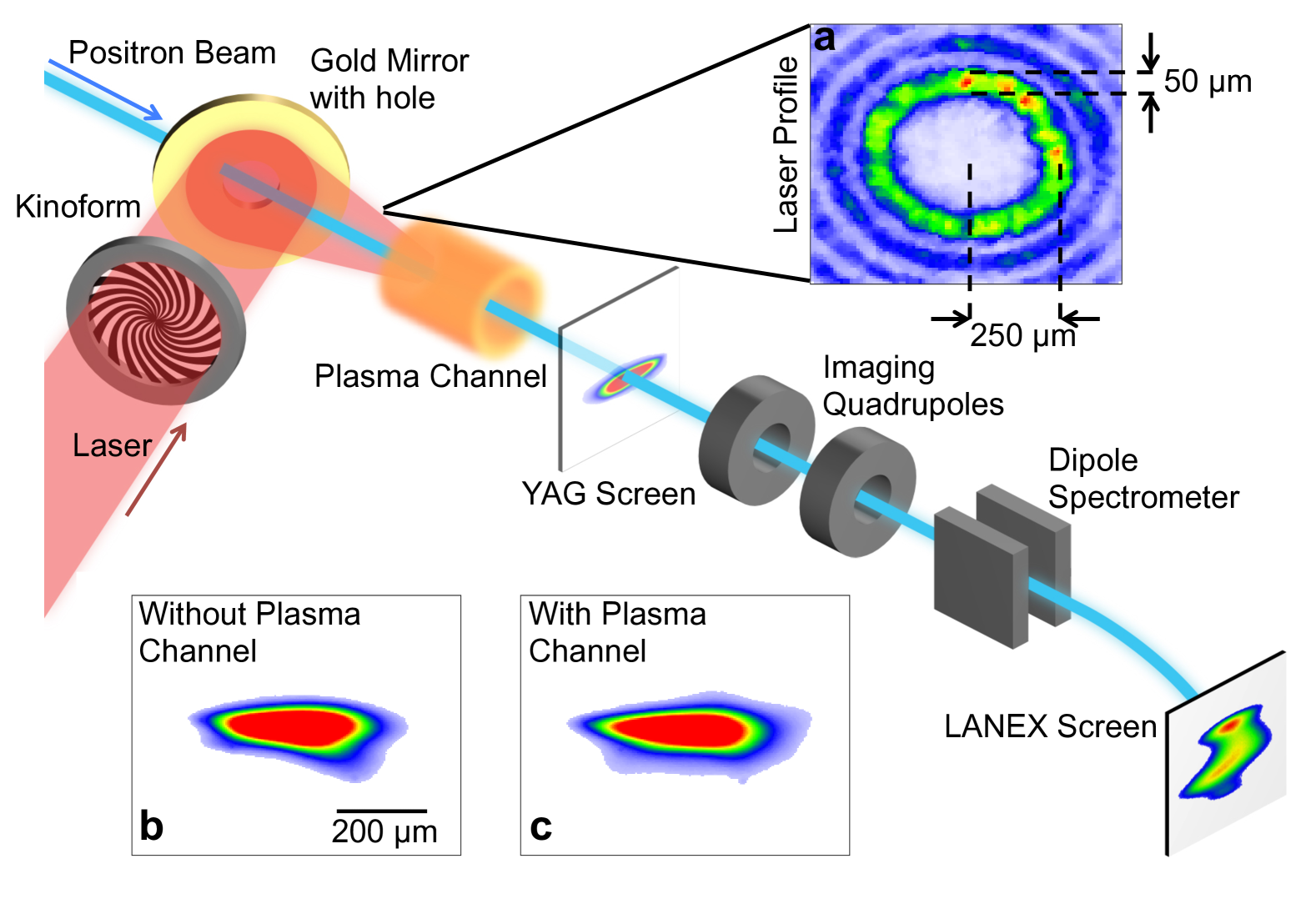
Figure 28 illustrates the experimental setup used for a demonstration performed by Gessner et al. [166], with a channel radius of and a plasma density of . The positions of both the positron beam and the high-order Bessel mode were measured on optical-transition-radiation (OTR) foils upstream and downstream of the plasma, such that the positrons and Bessel beams could be aligned. A mirror located downstream of the plasma source reflected the spent laser pulse out of the beamline to cameras imaging the OTR foils. The laser-imaging system tracked the position of the Bessel mode, and beam-position monitors (BPMs) tracked the position of the positron beam. Starting from a positron beam aligned to the high-order Bessel mode, the laser was rastered with respect to the positron beam such that the transverse offset of the laser and positrons changed, but their relative angle was fixed. During a raster scan, the distance of the positron beam to the center of the hollow channel varied, which induced transverse wakefield kicks to the beam [450]. The beam deflections were measured on screens and BPMs downstream of the plasma channel; the resulting kick map was used to reconstruct the shape of the plasma channel, demonstrating that a hollow-channel plasma was successfully generated.
In nominal operation, the positron bunch was aligned to the channel center and induced a longitudinal wakefield while losing up to of energy for a channel length of [166]. A trailing positron bunch then sampled the wakefield to map the accelerating and decelerating phases [168]; a peak accelerating gradient of was measured. The wavelength of the wakefield was observed to be much longer than the naïve theoretical prediction. A possible explanation is that the transverse profile of the hollow channel did not have sharp boundaries—a slow transition from the un-ionized channel center to the fully ionized wall increases the wavelength of the on-axis longitudinal field [461].
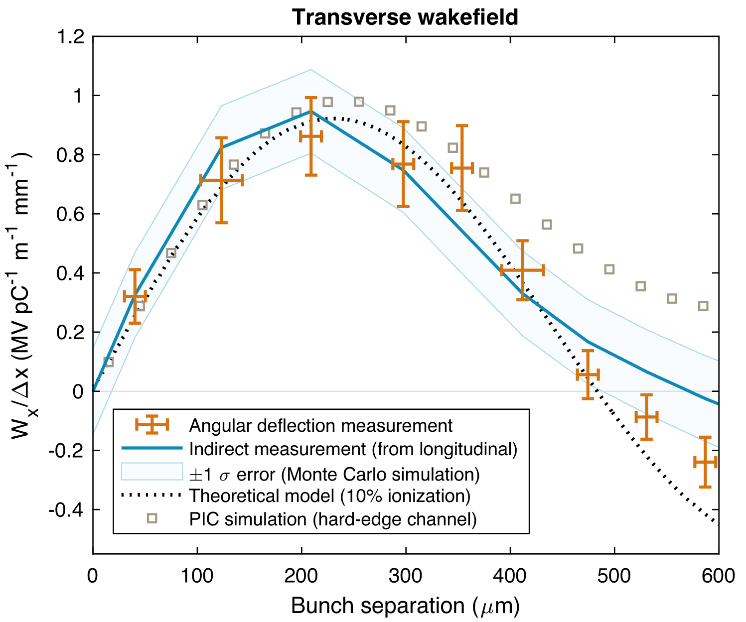
Finally, the experiments also highlighted the challenge of transverse instabilities. Leveraging random transverse laser jitter, as measured by downstream cameras, the angular deflection of the outgoing trailing positron bunch could be correlated with the relative beam–channel offset. This provided a measurement of the transverse wakefield [Eq. (34)] that causes the beam-breakup instability in the hollow-channel regime [450]. Using a range of different longitudinal driver-to-trailing-bunch separations, the longitudinal shape of the transverse wakefield was mapped (see Fig. 29), showing reasonable agreement between linear theory, experiment and PIC simulations. The maximum amplitude of the transverse wakefield was measured to be [288], which is over 3000 times stronger than that in a CLIC cavity structure [547]. The issue of transverse wakefields and beam-breakup instability in the hollow channel is a significant limitation for this regime. Traditional mitigation strategies include external focusing [161, 274] and BNS damping [26], but would necessitate large energy spreads . Alternative mitigation strategies are needed, but it is an open question as to whether or not mitigation can be achieved without relying on plasma-electron focusing. For example, the proposal by Zhou et al. [554] (see Sec. III.1.1) precisely relies on the focusing provided by plasma electrons from the channel wall flowing inward and into the positrons to stabilize the bunch.
III.1.3 In-situ positron generation and injection
Given the limited availability of conventional positron sources in accelerator test facilities, alternative techniques to provide positrons for injection into a plasma accelerator have been considered. Using a converter foil directly within the plasma or prior to it, a pair of co-propagating electron bunches can generate positrons overlapping in space with the incident electrons [519]. In the converter foil, electrons generate bremsstrahlung gamma rays that convert into electron-positron pairs via the Bethe-Heitler process, thus providing the source of positrons. Once in the plasma, the electron and positron bunches experience either a focusing or defocusing force from the plasma wakefield, where defocusing results in loss of the bunch. Choosing an appropriate longitudinal separation between the two electron bunches, only a leading electron bunch and a trailing positron bunch remain focused, with the electron bunch losing energy to the wake and the positron bunch being accelerated by it [518, 519, 520, 160, 14]. Despite a trade-off between the positron charge and emittance obtained with this technique, such in-situ positron generation and injection provides a more affordable means of experimentally testing positron acceleration in plasmas. A similar method can also be employed in laser-driven plasma accelerators, where an electron bunch accelerated in a first stage is used to produce positrons in a converter foil, subsequently injected and accelerated in a second laser-driven stage [435, 14, 473]. Going beyond positron production in converter targets, the Breit-Wheeler process has also been considered as a means to generate positrons from ultrahigh-intensity lasers [322, 295, 470].
III.2 Proton drivers and self-modulated wakefields
The vast majority of plasma-wakefield experiments utilize electron bunches as the drive beam. Recently, attention has turned towards using proton beams as drivers of plasma wakefields. This is because proton beams can be accelerated to much higher energies and with much higher bunch charges than electron beams. The total stored energy in these proton beams is in the kJ–MJ range, whereas electron beam drivers typically contain a few joules. If even a fraction of the proton beam’s energy is transferred to a trailing electron bunch, it will be possible to accelerate the electron beam to TeV-scale energies in a single plasma stage [66].
The central challenge associated with the proton beam-driven approach is that the proton bunches are much longer than the plasma wavelength at relevant plasma densities. The proton bunch length is determined by the rf frequency employed by the proton synchrotron ring, which is of order [ m]. On the other hand, even the longest plasma wavelengths used in PWFA are less than : with , the proton bunch cannot drive a high-amplitude wakefield. The solution to this challenge is to modulate the proton bunch into micro-bunches spaced at the plasma frequency [260] (covered in Sec. III.2.1), which resonantly drive a wakefield [299] into which electrons can be injected (covered in Sec. III.2.2), as depicted in Figs. 30(a–b). For a detailed review of proton-driven PWFA, see Adli and Muggli [3].
III.2.1 Formation of self-modulated wakes
In the self-modulation process, the proton beam drives a small-amplitude wakefield that acts back on the bunch: the protons are alternately focused and defocused with a longitudinal separation determined by the plasma frequency. The focused portions of the bunch enhance the strength of the wakefield, leading to a stronger focusing–defocusing pattern. The growth rate of this process is given by [406, 445]
| (74) |
with , bunch density , proton mass , and beam Lorentz factor . The process continues until a train of micro-bunches is formed and the modulation saturates. While each micro-bunch contains only a small fraction of the total bunch charge, together they resonantly drive a large-amplitude wake [7, 481]. This effect has also been observed with long () electron bunches propagating in plasma [140, 188] as well as with laser drivers [232, 478].
When the self-modulation is seeded by Schottky noise from the proton drive beam, it is referred to as the self-modulation instability (SMI) [307]. Alternatively, the modulation may be induced by a seed pulse or structure to produce a phase-stable wakefield [447], in which case it is referred to as self-seeded modulation (SSM). SSM seeds include sharply-featured bunches [140, 188], relativistic ionization fronts (RIF) [35, 498], and dense electron beam drivers [497]. Figures 30(c–d) show the effect of the self-modulated wakefield on the proton driver when the wake is seeded by a RIF. If the RIF is more than ahead of the beam centroid, the Schottky noise becomes the dominant seed and control over the wakefield phase is lost [167]. Accurate prediction of the wakefield phase is critical for successful injection of a trailing electron bunch into the self-modulated wake [309, 374], which is only achievable through the SSM process. Additionally, an externally-seeded wake suppresses the deleterious hosing instability [447, 508] (see Sec. II.2.3). Hosing can also be seeded or suppressed by controlling the relative alignment of an electron seed bunch to the proton bunch [361].
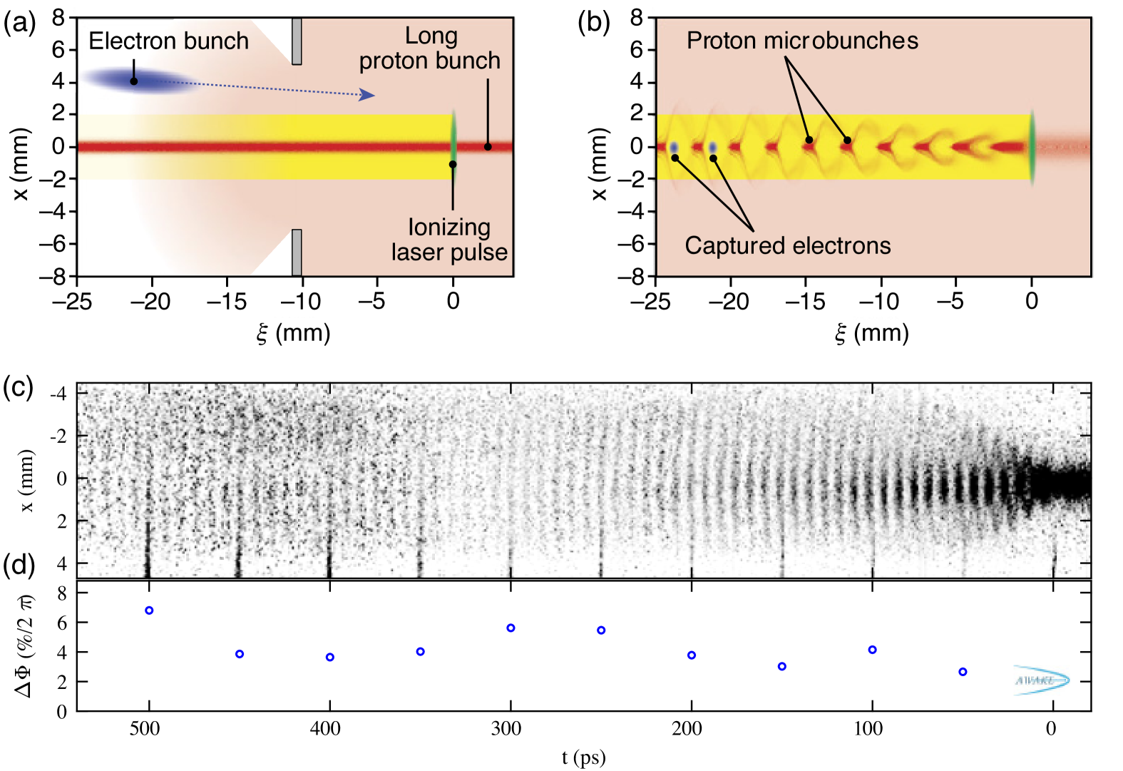
For both seeded and unseeded wakefields, the growth rate of the wake amplitude depends on the longitudinal position within the bunch and the distance traveled through the plasma . The fact that the growth rate depends on leads to a change in the phase velocity of the wake over the length of the drive bunch, given by [406, 445]
| (75) |
The phase velocity may be considerably less than the bunch propagation speed . This poses a challenge for accelerating electrons in the self-modulated plasma wakefield, as the electrons will reach velocity close to almost instantly and transition between accelerating and decelerating phases of the wake (see Sec. II.3.1). In addition, the wake amplitude is predicted to decay after the self-modulation process saturates [304].
To address issues related to the varying phase velocity and decaying amplitude of the self-modulated plasma wakefield, two approaches have been proposed. First, longitudinal plasma-density gradients have been studied [446, 308] and demonstrated [53, 346] to stabilize the phase velocity of the wake. Second, an abrupt step in the density gradient has been proposed to “freeze” the wake amplitude near its maximum [304, 305, 389]. Steps in the plasma density have also been proposed to de-tune the hosing instability [347].
III.2.2 Capture and acceleration of electrons
Beyond the phase stability of the wake, there are challenges associated with electron beam injection into the wake due to defocusing fields in the ramps and radial edges of the plasma [309, 183]. Off-axis injection [as shown in Fig. 30(a)] avoids the deleterious fields at the entrance of the plasma [68], but introduces emittance growth due to the beam entering the wake with transverse momentum. This method was successfully employed in the first experimental demonstration of electron acceleration in a proton-driven wakefield [6] up to (see Fig. 42), in the AWAKE facility at CERN (see Sec. IV.2.5). Alternatively, on-axis injection is possible if the self-modulation has fully saturated [374]. AWAKE plans to demonstrate this concept by separating their plasma source into a self-modulation stage for the proton bunch only, followed by electron injection into an acceleration stage using the fully modulated proton beam [194]. In this scenario, it is possible to preserve the emittance of a high-charge electron bunch [374], which superimposes a blowout wake on the self-modulated wake, but at the expense of increased energy spread due to heavy beam loading [142] (see Sec. II.3.1).
III.3 Internal injection of plasma electrons
The injection of electrons into a plasma wakefield from inside the plasma is a common technique in LWFA experiments, but is less explored experimentally in beam-driven PWFAs. This is because self injection or wavebreaking (see Sec. II.1.6) cannot easily occur in beam-driven PWFAs when the plasma wave travels at the speed of the drive beam (i.e., very close to ). Thus electrons from the plasma, which need to reach the wake velocity within the first wakefield period to be injected, cannot achieve the required energy for wavebreaking. This can be seen as an inherent advantage of PWFAs, as unwanted trapping of charge from self-injection, or “dark current” [315], is typically absent.
A variety of methods have been proposed to achieve trapping of electrons or trigger wavebreaking in a beam-driven plasma cavity. These schemes can be broken down into two categories: ionization of electrons directly within the wakefield (Sec. III.3.1); or by reducing the phase velocity of the wake such that streaming electrons traveling close to the speed of light can intercept the back of the elongating wake, so-called “downramp injection” (Sec. III.3.2). Other schemes also exist, including using a pulsed magnetic dipole field to alter the trajectory of streaming electrons [506].
By promising to produce electron beams with transverse normalized emittances orders of magnitude smaller than those produced by rf photocathode guns [276], such plasma-based internal injection represents an attractive prospect in ultra-low-emittance applications, e.g. at FEL facilities or linear colliders (see Sec. V).
III.3.1 Ionization injection
In any of the ionization-injection schemes discussed in this section, it is insufficient for electrons to simply be released inside the wakefield; they must also be trapped by the potential well of the wake. A sufficient condition for trapping is met when the velocity of the plasma electrons, , exceeds the wake phase velocity, . However, a more general trapping condition can be found in terms of the pseudo-potential (introduced in Sec. II.1.3), and is valid even when . From the Lorentz-force equation, the Hamiltonian for a test electron with Lorentz factor is , where is the scalar electric potential. Electron injection can then be modeled by considering the dynamics of a test electron in a quasistatic plasma wakefield (see Sec. II.1.3), for which depends on and only via . As a consequence of the quasistatic approximation (), we have [344]
| (76) | ||||
| (77) |
where is the longitudinal component of the electron’s canonical momentum and similarly of the vector potential . The quantity is thus a constant of motion, which can be rewritten as
| (78) |
Under the assumption that the electrons are released (or born, following ionization) from rest (, initially) with a pseudo-potential , the right-hand side of Eq. (78) is . For a wake traveling at the speed of light (), Eq. (78) and the inequality forbid the test electron to move into regions of space where . For strong plasma wakes with pseudo-potential variation exceeding 1, this condition can effectively confine and trap a test electron inside regions where or equivalently . Physically, the test electron initially recedes towards the rear of the wake and is injected as , and , where it essentially moves at the same speed as the wake and its position asymptotically converges towards its final location defined by . The trapping condition can thus be stated as the existence of initial and final positions such that [326]. Figure 31 illustrates the pseudo-potential well of a beam-driven wake sufficiently deep to trap electrons ionized within it.
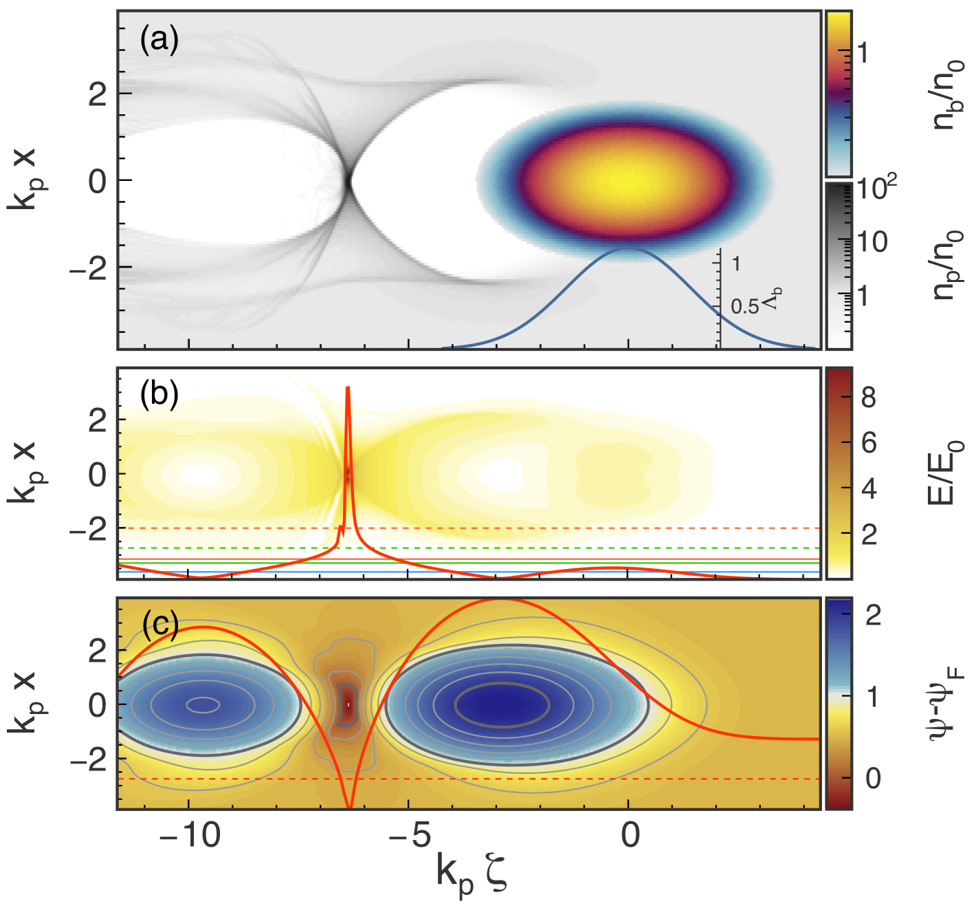
In ionization injection, the electrons are released into the plasma wake from a previously un-ionized gas component or ionization level. This is typically achieved by generating a plasma with a low-ionization-threshold (LIT) gas species, in which a beam drives a wake. Electrons may then be born inside the wake when the ionization threshold of a high-ionization-threshold (HIT) component of the plasma is overcome. This concept was first proposed [485] and demonstrated in LWFAs [380, 330, 84, 397]. Ionization injection can be achieved in PWFA by using the electric fields of the wake, beam, or a high-intensity laser, as discussed below.
Wakefield-triggered injection
The electric field of the wake can itself be strong enough to ionize and trap electrons, specifically at the rear of the ion cavity [323, 326], as shown in Fig. 31(b). A high-peak-current beam () is required in order to generate wakefields sufficient for this scheme. For high beam quality, the area of injection needs to be restricted to the back of the wake period such that unwanted trapping of electrons ionized by the driver fields (see Sec. III.3.1 below) can be avoided. This can be achieved by restricting the HIT dopant to a small region at the beginning of the plasma source before beam-pinching can occur [323]. So far, the mechanism has not been experimentally demonstrated but the predicted beam properties, including attosecond bunch lengths, are promising. Given that these beams could drive a blowout in a subsequent stage with a higher plasma density, “self-similar staging” was proposed [326], whereby each stage boosts the brightness of the previous stage.
Beam-triggered injection
If the relativistic beam driver is focused to a very small beam size ( scale), its radial electric field, often combined with the wakefield, can ionize electrons from a HIT component. Typically, this only occurs when the focusing force of the blowout ion column causes envelope oscillation and pinching of a mismatched beam driver (see Sec. II.2.1 and Fig. 22). Because of the relative simplicity of the scheme, it is one of the few with multiple experimental demonstrations, both by Öz et al. [378] (see Fig. 32) and by Vafaei-Najafabadi et al. [487], the latter also demonstrating that the injected electrons altered the wake through beam loading (see Sec. II.3.1). Further, simulations as well as experimental evidence [489] indicate that this method can produce multiple distinct bunches of different energy, useful e.g. for producing two-color FEL gain (see Sec. V.2).
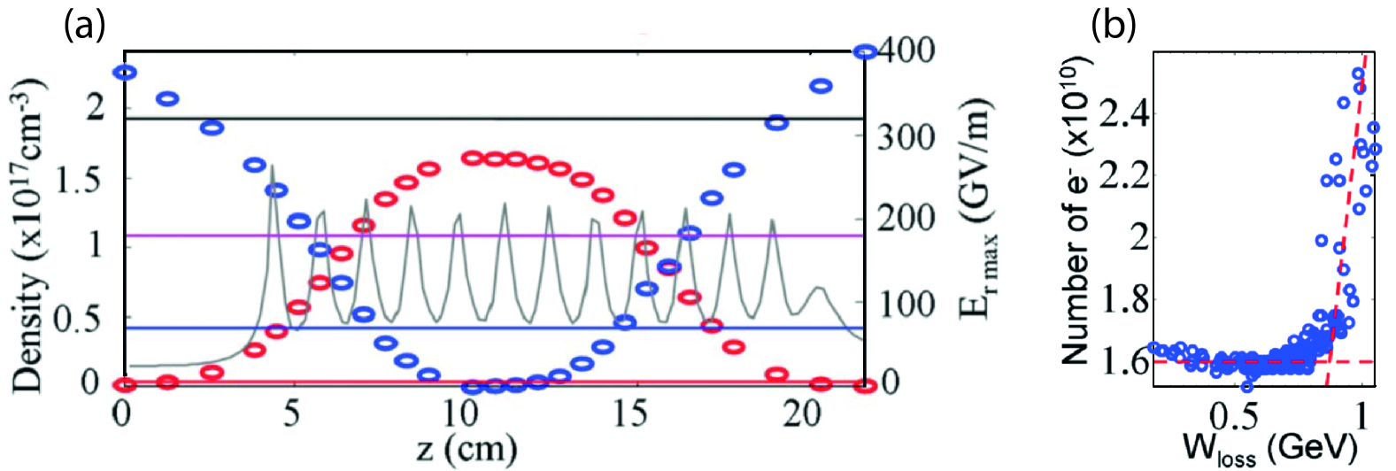
Laser-triggered injection
Instead of the beam field or the wakefield itself triggering ionization, it is possible to use a high-intensity laser pulse intercepting the wake to ionize a small volume inside. This typically requires a high-peak-current beam to ensure trapping from rest, but is more relaxed than for the above schemes since the ionization may be produced in the wake center (i.e. at the location of maximum trapping potential) [see Fig. 31(c)].
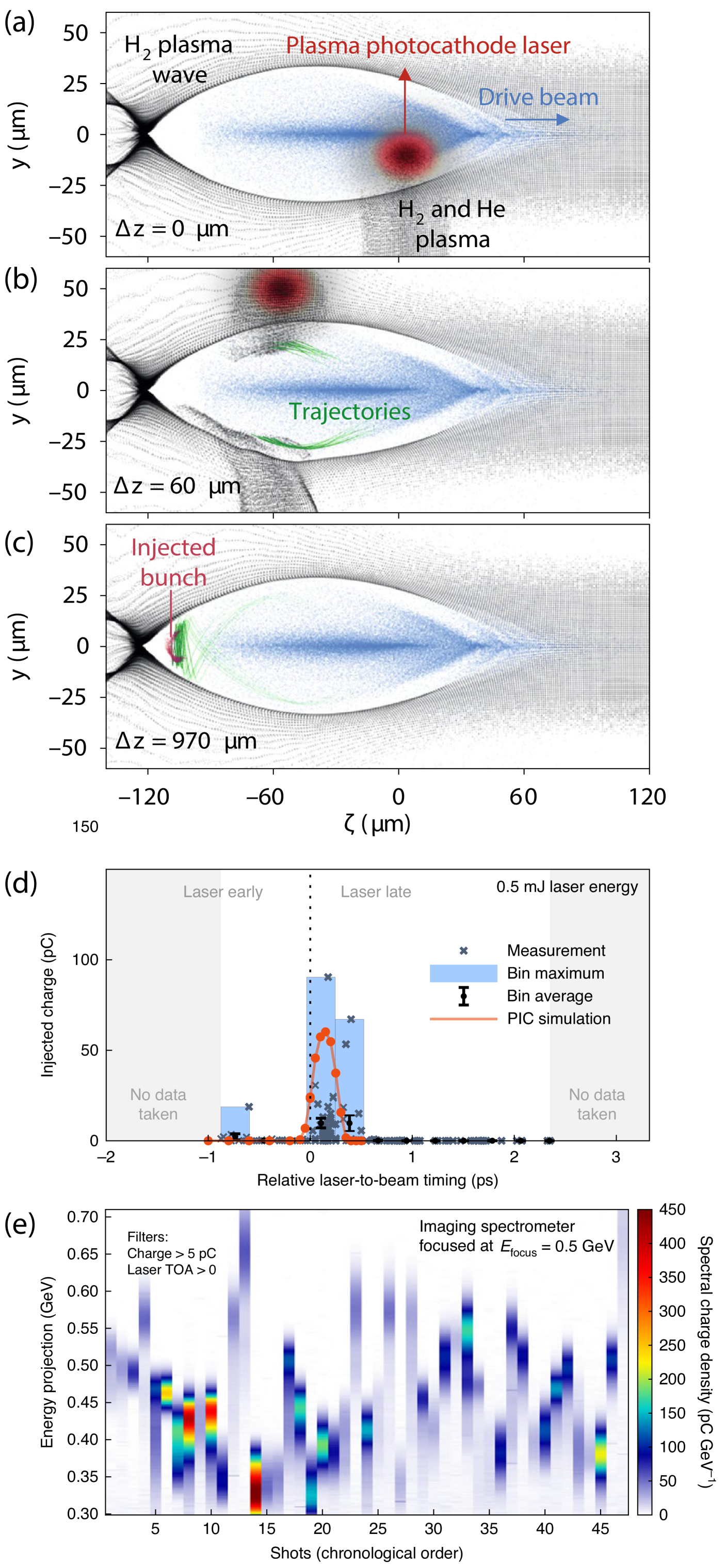
An example of laser-assisted injection, referred to as a “plasma photocathode”, uses a high-intensity laser co-propagating directly behind a high-peak-current beam driver with the laser focal plane situated close to the beginning of the acceleration stage [205]. The laser parameters are chosen such that it only ionizes the HIT dopant at and around its waist, so that the ionization is localized in a small volume and occurs over a short timescale—achievable with a Ti:Sapphire laser of moderate strength. This requires high spatial and temporal precision; a small fraction of the plasma wavelength and oscillation period, respectively. The resulting electron beams can have very low normalized transverse emittance () when the electrons are released close to the wakefield axis, enabled by the moderate laser vector potential requirements for ionization, which mitigates ponderomotive heating. A variation on this scheme, using a transverse rather than co-propagating ionization laser [see Figs. 33(a–c)] has been experimentally demonstrated [109] [see Figs. 33(d–e)].
The trapping conditions on the drive-beam peak current can be further reduced by utilizing the ponderomotive force of an obliquely incident laser to ionize electrons and accelerate them into the propagation direction of the plasma wakefield to facilitate trapping [544]. However, this comes at the expense of an increase in emittance. A more complex laser-assisted injection scheme based on beat waves, whereby two counter-propagating transverse lasers interfere and trigger ionization from within the wake [276] (see Fig. 3), may lead to ultrashort () beams with moderately high peak current () and ultralow emittance () owing to a decreased injection volume.
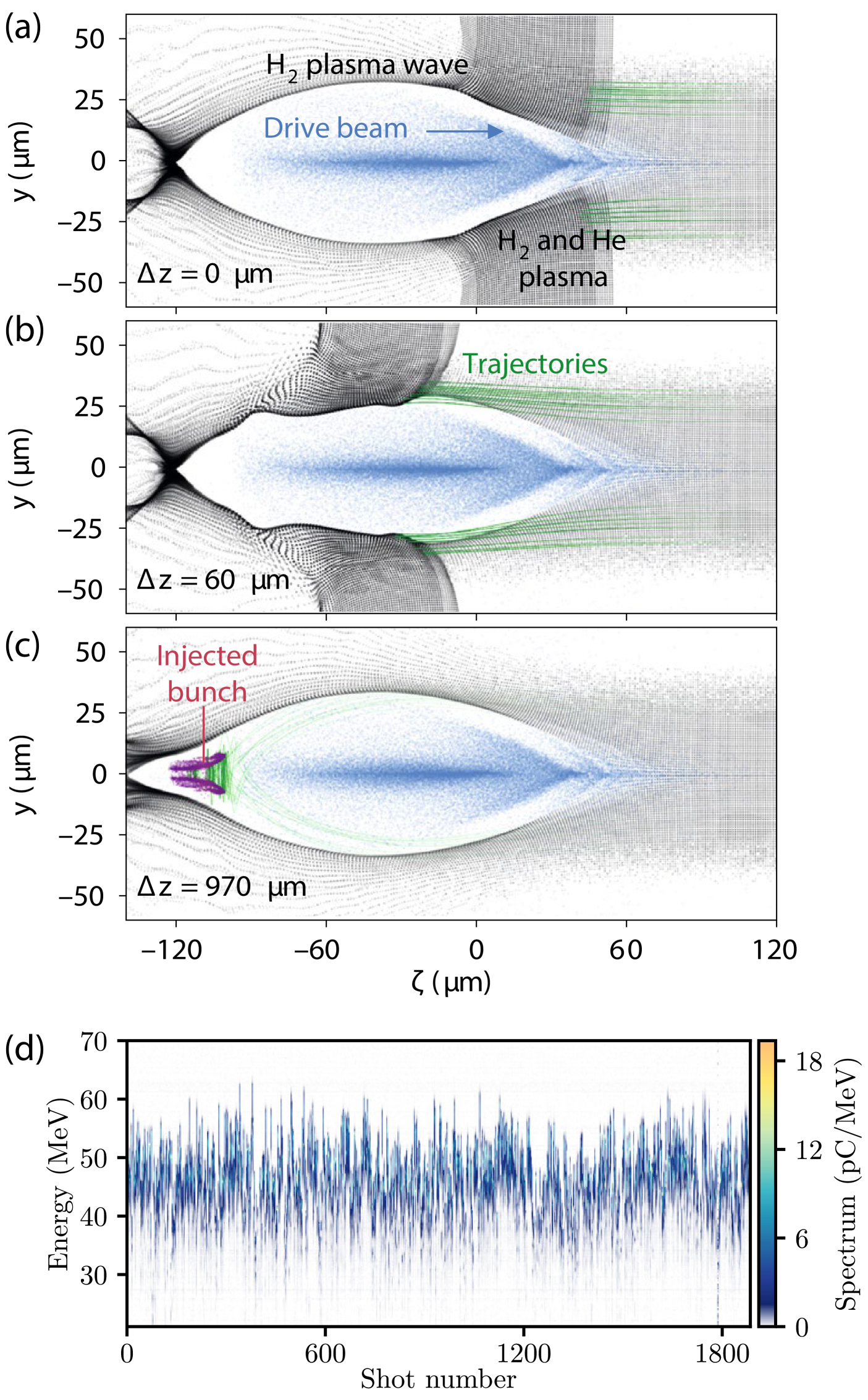
III.3.2 Phase-velocity reduction and downramp injection
Streaming plasma electrons can be injected into the wakefield by temporarily reducing the phase velocity of the wake, , to below the speed of the plasma electrons, , via a dynamic elongation of the wake period. Defining an effective plasma frequency and wavenumber , the local phase velocity of the wake is given by , i.e.
| (79) |
where is the co-moving coordinate and is the local phase of the plasma wave, assuming the driver moves at and is located at [60, 132]. According to Eq. (79), the phase velocity of the wake can be locally reduced by a negative wavenumber gradient in (noting that behind the driver). This is achieved in practice by introducing a density gradient in the longitudinal plasma-density profile—so-called downramp injection. Alternatively, it can be achieved by decreasing the driver spot size in the plasma, either with strong external focusing or using a mismatched beam, such that the kinetic energy of the plasma electrons increases [98]. In each case, the blowout-cavity length increases. As the wakefield driver propagates in an expanding blowout cavity, the phase velocity of the wake decreases until it becomes equal to or smaller than the maximum forward velocity of the oscillating plasma electrons, resulting in wavebreaking. A sufficient condition for trapping in an adiabatically evolving wakefield is [236, 542], where is the variation of the nonstationary Hamiltonian of a plasma electron in the comoving coordinate system (). Here, in contrast to Eq. (77), is not constant because the wakefield is evolving during trapping.
The concept of trapping using a density downramp was first proposed for LWFA [60], in which a gentle density drop much longer than the plasma skin depth facilitates injection of background plasma electrons. Later, Suk et al. [471] suggested that a sharp density transition with length less than a plasma-skin depth be used, such that plasma-electron trapping occurs due to a localized non-laminar motion near the sharp density transition and at wake amplitudes well below the wavebreaking threshold [see Figs. 34(a–c)].
Experimentally, density downramps are often generated hydrodynamically, including by means of shocks in a gas flow then turned into plasma, first demonstrated in LWFA [441] and later achieved in PWFA [93] driven by electron bunches from an LWFA. This was extended to optically-generated hydrodynamic shocks [155], also in a hybrid LWFA-driven PWFA (see Sec. IV.2.8). An alternative method for the generation of sharp density transitions is using a transverse ionization laser [527]. This method, known as “plasma torch” injection, offers increased flexibility and was first used at FACET (Sec. IV.2.4) to establish temporal overlap of the transverse laser with the plasma wake [440] in the plasma-photocathode experiment [109]. Subsequently, the method was demonstrated by Knetsch et al. [251] with improved stability at FLASHForward (Sec. IV.2.7); see Fig. 34(d).
The injection dynamics and the quality of the generated beams have been studied with simulations, and the results are somewhat complex. For downramp lengths of a few plasma skin depths, Martinez de la Ossa et al. [324], Grebenyuk et al. [185] showed that shorter ramps result in reduced slice emittances, whereas the amount of injected charge diminishes drastically when the length of the ramp is increased. Zhang et al. [548] showed that the slice emittance can be reduced from 0.1 to by using a gentler ramp and increasing its length from 5 to 25 . Xu et al. [537] uncovered a new mechanism that leads to the generation of unprecedented beam brightness in downramp injection with gentle ramps. In the high-density electron spike at the rear of the blowout cavity, electrons experience defocusing fields that can reduce their transverse momentum just as they are streaming into the wake to be trapped. These defocusing fields vanish once injected in the blowout cavity, and with proper optimization, electrons become trapped with extremely small residual transverse momenta, and thus with ultralow emittances and very high brightness. For both gentle ramps [537] and evolving drivers [98], the resulting 6D brightness [Eq. (51)] scales linearly with the plasma density and can reach for a plasma density of cm-3. Driving PWFA at such plasma densities could be enabled by the intense beams of the FACET-II facility (Sec. IV.2.4). For the slice energy spread of reported in these studies, this also corresponds to a 5D brightness of . Finally, Zhang et al. [548] showed the practical importance of cylindrical beam symmetry, with injected beam emittances up to 10 times larger for noncylindrical drivers compared to that of cylindrical drivers.
III.4 Long-term plasma evolution
The average beam current is an important figure of merit for the performance of an accelerator as it is proportional to the integrated luminosity of a collider (see Sec. V.1), i.e. the number of collision events within a certain time, and the average brilliance of a light source (see Sec. V.2). To compete with rf technology, plasma accelerators must be capable of accelerating thousands or even millions of bunches per second. Unlike with rf technology, the quality factor of a plasma accelerator is low [369], such that the electromagnetic wave damps after only a few to tens of oscillations. This means that energy should be maximally extracted from the first oscillation cycle, after which the plasma is left to equilibrate (or recover) until a following, similar acceleration event can be driven. The long-term evolution of the plasma thus plays a critical role in determining the maximum number of acceleration events per second.
The initial perturbation and subsequent motion of plasma ions is expected to be one of the main mechanisms in determining the long-term evolution of the plasma. Ions are typically considered static on the timescale of the plasma-electron wavelength due to their high mass compared to that of electrons. This is typically an adequate assumption when modeling plasma dynamics close to the driver. However, on longer timescales, and for high-density drivers, the motion of plasma ions becomes important. There are two main forces acting on the ions. Firstly, the ions may be accelerated directly by the fields of the beams. This is especially relevant for dense beams () as this can cause a collapse of the ions onto the beam axis within the first plasma-electron wavelength, resulting in a distortion of the accelerating and focusing fields [429] (see Sec. II.3.2). Secondly, the trailing plasma wave exerts a ponderomotive force (integrated over all existing plasma-electron periods) on the ion background, which lasts until the plasma-electron wave eventually breaks down. This process was first predicted for laser drivers [181, 182] and later adapted for long proton drivers [503, 504] (see Sec. III.2), the latter of which has recently been demonstrated experimentally [483] at AWAKE (see Sec. IV.2.5).
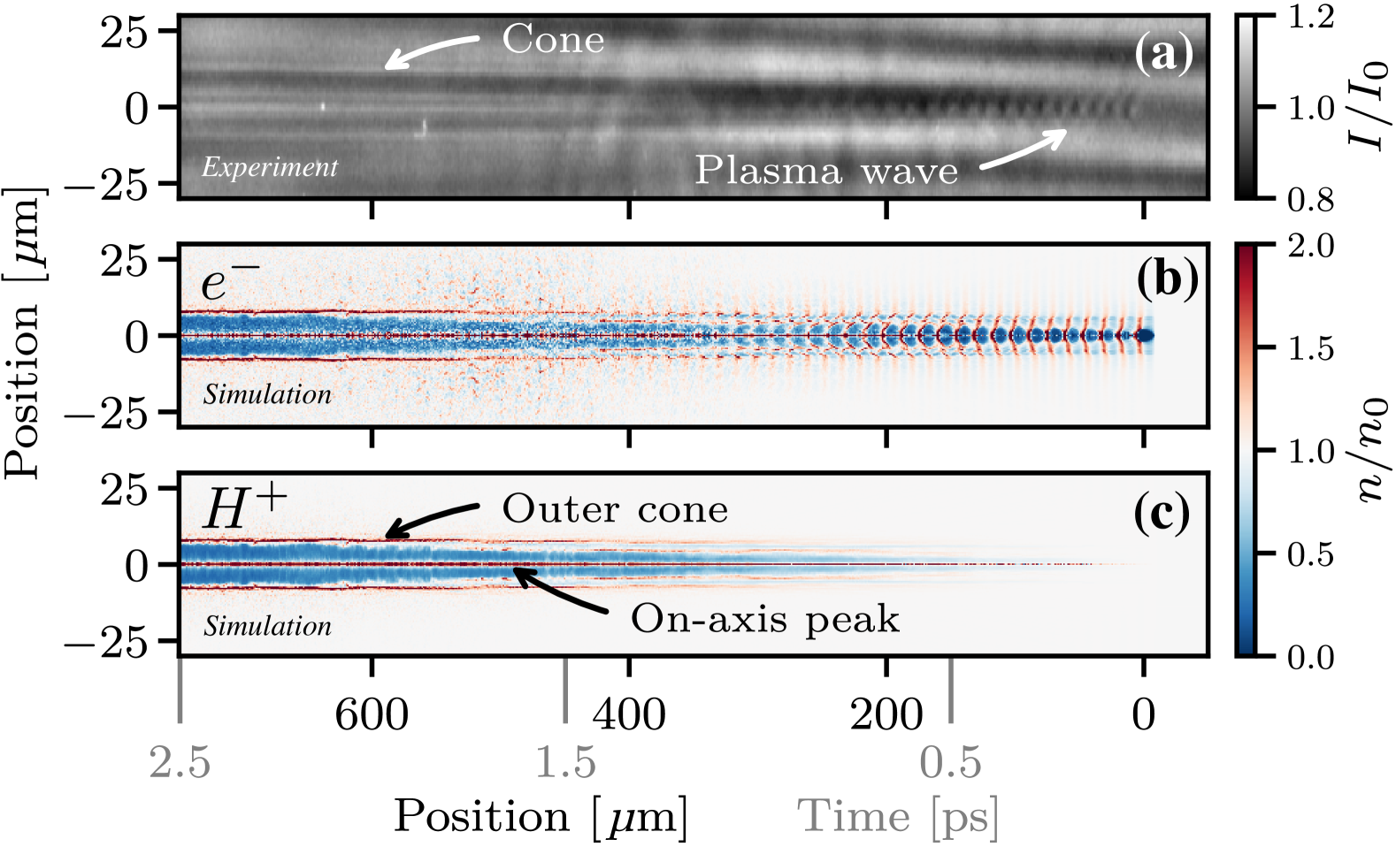
These studies show that the ponderomotive force of the plasma wave leads to the formation of an annular channel with an on-axis peak in the ion density at very early timescales. A transverse shadowgraphic [59, 453, 439] measurement of the ion-channel formation is shown in Fig. 35 [172]. Here, a few-fs-long probe laser pulse is propagated transversely through the plasma wave, where the plasma-density perturbations lead to a local phase retardation that results in a shadowgram. The plasma wave is driven by a and fs-long electron beam (from an LWFA; see Sec. IV.2.8) with in a hydrogen plasma of density . The ion channel starts to appear after several plasma periods and lasts for at least tens of picoseconds—the diagnostic reach is limited by the maximum achievable delay between the drive- and probe-pulse. Simulations show that the formation of the ion channel causes the plasma wave to break down, after which time electrons follow the accelerated ions and the plasma becomes mostly neutral.
Going further, into the nanosecond timescale, an experiment at FACET (see Sec. IV.2.4) measured the formation of a meter-scale ion channel by using grazing-incidence shadowgraphy [546]. This technique, in which the probe and drive beams have a shallow oblique angle [278], is suitable for probing targets not easily accessible with transverse probes, such as enclosed or long targets. This enabled the measurement of ion-channel evolution over timescales of up to . Corresponding numerical simulations suggest that the majority of energy deposited in the plasma is initially transferred from the driving beam to the plasma electrons, with eventually about 90% of the total deposited energy transferred to the plasma ions on the ns-timescale due to electron–ion and subsequent ion–ion collisions.
Studies at FLASHForward (see Sec. IV.2.7) went even further by measuring the time it takes for the coherent motion of the plasma ions to equilibrate, thus setting a timescale for the “recovery time” of the plasma [102]. This was achieved by exciting the plasma with an initial GV/m wakefield event and using a probing drive–trailing bunch pair with variable delay to sample the evolving plasma properties. This showed that the plasma recovered within (see Fig. 36), after which the energy of the probe-bunch pair was no longer influenced by the presence of the previous driver. This recovery time would in principle support repetition rates on the order of , making plasma accelerators compatible with the bunch-train patterns of current FELs and future linear-collider facilities. Simulations of the plasma motion show that the accelerated ions move radially outwards in the form of an ion acoustic wave, with the on-axis depletion of ions replenished by inwardly streaming cold ions from beyond the radius of the plasma wave. The equilibrated plasma profile can then be used for a subsequent acceleration event. Further studies at SPARC_LAB (see Sec. IV.2.6) have been performed in a hydrogen plasma [402].
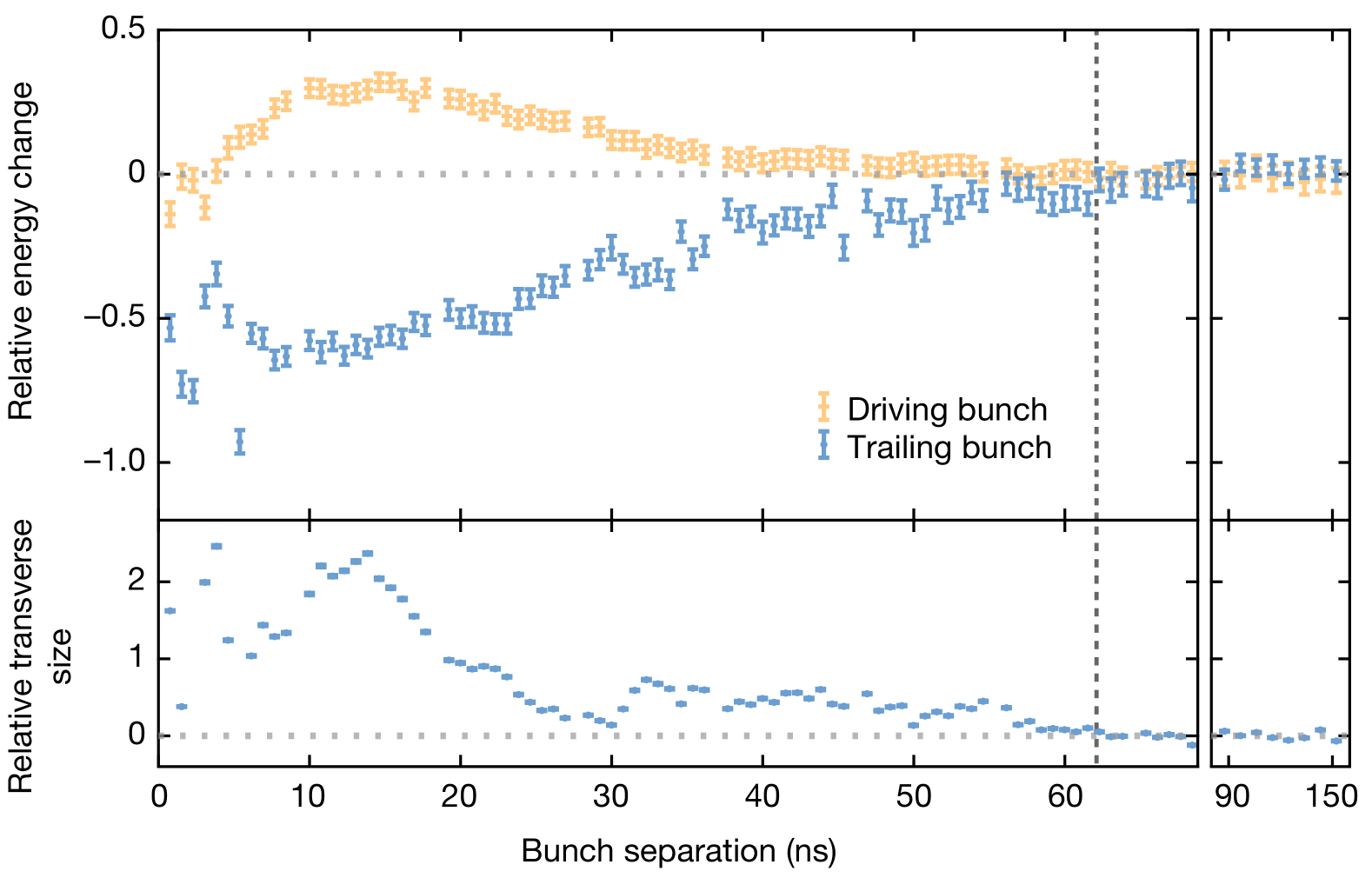
Long-term plasma motion is stimulated by residual energy transferred from the drive bunch to the plasma and not extracted by the trailing bunch (see Sec. II.3.1). Although the average plasma profile was shown to have recovered (Fig. 36), the cumulative energy deposited in the plasma from sustained acceleration at high repetition rates will likely result in large thermal energies (i.e, keV). Such thermal energies are expected to modify the wakefield properties, although limited numerical studies of non-zero plasma-temperature effects have been performed (see Sec. II.1.6). Furthermore, some proportion of the remnant energy in the plasma will conductively heat the surrounding plasma-cell material. High-average-power plasma stages will therefore necessitate the consideration of temperature-stabilization techniques.
III.5 Multistage acceleration
Accelerating particle bunches of high charge to high energies is one of the main goals for PWFA. This requires efficient transfer of energy from drivers with high energy content. In linear colliders (see Sec. V.1), for instance, the colliding bunches each contain of order . However, electron drivers of the required spatial dimensions typically only contain of order or less, which means multiple drivers are required—each in their own accelerating stage. Only proton drivers are able to extend this energy-depletion limit, as proton bunches can be accelerated to very high energies in synchrotrons (see Sec. III.2); e.g., per particle and per bunch at Super Proton Synchrotron (SPS) [191]. That said, the repetition rate and energy efficiency of proton bunch production is currently too low for linear colliders. Therefore, use of multiple stages—known as staging—is likely required, at least for high-luminosity particle colliders. In practice, staging is challenging and has only seen rudimentary experimental exploration, as detailed below. For a more complete review of staging, see Lindstrøm [281].
The staging problem stems from the fact that plasma accelerators focus the trailing bunch strongly, which leads to small beta functions and beam sizes inside the stages and highly diverging beams outside. Since some space is required to extract the depleted driver and re-inject a new one, stages must be separated (by up to several meters, depending on the energy). This leads to issues with preservation of beam quality and overall compactness.
Refocusing and chromaticity
The first issue is that the high-divergence trailing bunch expands rapidly and must be refocused into the subsequent stage. This is problematic because the beta function in the refocusing lens(es) is large compared to inside the stage , which leads to strongly energy-dependent focusing, known as chromaticity [556]. This is often quantified using the chromatic amplitude , which if unmitigated increases by approximately in a focusing element, where is the focal length and is the distance from the stage to the refocusing lens. Approximating , the relative (squared) emittance growth from chromaticity [18, 338] can therefore be approximated as
| (80) |
where is the relative energy spread. As an example, consider a beam with around 0.5% energy spread: if the plasma density is , the matched beta function would be of order , and the stage-to-lens separation around (assuming focusing strengths ), resulting in an emittance growth of about 100% per stage—clearly unacceptable if multiple stages are used. Using a more detailed model, Thomas and Seipt [475] found that a linear collider (accelerating beams to over 85 stages) would require maintaining an energy spread below in order to keep emittance growth below , which would be extremely challenging in practice. Instead, we must either greatly reduce the chromaticity, by reducing the focal length of the lens or by increasing the matched beta function of the stage. Short-focal-length beam optics include plasma lenses, which come in two forms: active plasma lenses, which use the azimuthal magnetic field from an electrical current through a plasma [381, 490, 398, 289]; or passive plasma lenses, which use the strong electric fields in a plasma wake [76, 362, 319, 121]. Increasing the matched beta function is possible by use of plasma-density ramps [321, 120, 538, 20] at the entrance and exit of the stage (discussed in Sec. II.3.2). Alternatively, we can introduce achromatic (and nonlinear) beam optics [341, 284] between the stages—a strategy successfully employed in linear-collider final-focus systems [408, 523], but at the cost of significantly increasing the accelerator length. Recent work suggests combining these solutions by using nonlinear plasma lenses [123].
Geometric accelerating gradient
The second issue, which is related to the required optics, is that separating the stages ultimately reduces the longitudinally averaged (or geometric) accelerating gradient of the plasma accelerator. Importantly, because refocusing is required, the interstage distance increases with energy. The length scaling can be found by considering that the focal length of the refocusing lens must be proportional to the interstage distance: , where and are the length and strength of the refocusing lens, respectively. If the lens is operated at maximum strength , where is a constant field strength and is the particle momentum at that stage, and that the lens takes up a given fraction of the interstage distance (i.e., is constant), we find that , or equivalently . As a consequence, at some energy the distance between stages will exceed the length of the stage itself, and therefore, ultimately the total length of a multistage plasma accelerator will be dominated by staging, scaling as , where is the number of stages. For this reason, the number of stages should be minimized, although an optimization must also consider the longer rf accelerator needed to produce the drivers. Also relevant is the way drivers are distributed across multiple stages, for which concepts have been proposed [259, 2, 391]: this will take up significant space and must be considered as part of the overall size of a facility.
In- and out-coupling of drivers
In- and out-coupling, the process of merging and separating the driver and trailing bunches, is also non-trivial. The sub-ps separation between these bunches is too short for conventional kickers, which operate with ns or longer rise times. Unless ultra-fast plasma- or laser-based kickers are introduced, the bunches must be separated by energy, which requires the use of magnetic dipoles between stages. This introduces a transverse dispersion not only in the driver but also in the trailing bunch, which must be canceled to avoid emittance growth. Moreover, incoherent and coherent synchrotron radiation may be disruptive, at high and low energies, respectively. Finally, a magnetic chicane will introduce a longitudinal dispersion, , which can compress or stretch the trailing bunch. Naively, we would require , but recent work has shown that a non-zero can in fact be beneficial, leading to energy-spread compensation, if applied across two stages [145], or even a more complete self-correction mechanism in longitudinal phase space [282] if applied over many stages (see Fig. 37).
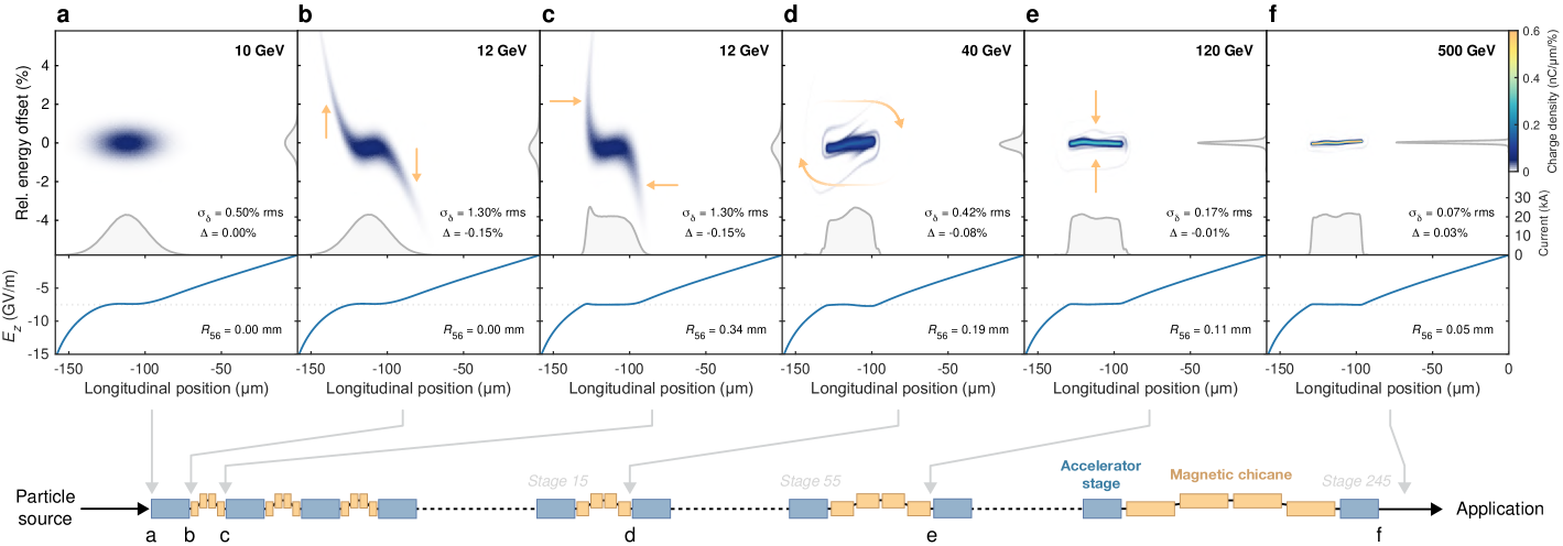
An alternative method is to use a driver train that traverses all the stages, and is progressively shifted backwards using a chicane between each stage [250]. If the plasma is formed just ahead of the trailing bunch (with a laser pulse), only the rear-most driver interacts with the plasma. This gated staging scheme greatly simplifies driver in- and out-coupling and distribution, but also requires picosecond-scale driver separations—challenging to achieve in an rf accelerator, though it is in principle possible [353].
Alignment and synchronization
Finally, staging influences the tolerances of both alignment and synchronization. The already strict misalignment tolerances for a single stage (see Sec. II.3.2) are made even stricter in a multistage accelerator, as each stage can separately contribute emittance growth. While the full dynamics is complex and yet to be fully explored, it is expected that if the misalignment of (the driver in) each stage is uncorrelated, the emittance growth will increase by a factor [77, 452, 285, 474]. The situation is different for synchronization tolerances between the driver and the trailing bunch, which a priori follows a similar scaling, but can in fact be significantly improved by use of multiple stages if a non-zero and the self-correction mechanism is applied [282] (Fig. 37).
To date, there has been no experimental demonstration of staging of beam-driven plasma accelerators. This will require a dedicated medium-scale facility (i.e., larger and more complex than current single-stage experiments), concepts for which are currently being developed. However, a relevant experiment was conducted using a two-stage LWFA at Lawrence Berkeley National Lab [466]: the first stage produced electron bunches with a broad energy spectrum (60% FWHM), then focused by an active plasma lens into the second stage, which added up to of additional energy gain. While successful at accelerating electrons, this experiment highlights the challenge of energy spread and chromaticity, as only 3.5% of the electrons were accelerated in the second stage. Nevertheless, the experiment was groundbreaking in its use of a plasma lens for refocusing, which is likely also to be key for staging PWFAs.
IV Research methods and results
How do researchers study beam-driven plasma wakefields and what is the experimental basis of the physics described in Secs. II and III? Decades of theoretical and experimental research have yielded numerous important methods and results, covered in Secs. IV.1 and IV.2.
IV.1 Numerical modeling and codes
Interactions between plasma and intense beams can require the description of individual particle dynamics and nonlinear phenomena not captured by a fluid-based, or hydrodynamic, model. In a collisionless plasma, typical for plasma accelerators, such interactions can be simulated with a kinetic description, using the particle-in-cell (PIC) method. Invented in the 1950s by Buneman, Hockney, Birdsall, Dawson and others [see the review by Nishikawa et al. [366]], the PIC method is based on charged particles moving in a grid of cells, in each of which electromagnetic fields are averaged. The method follows a basic four-step loop: (1) the charge and current density is calculated based on the particle distribution; (2) this is used to solve for the electromagnetic fields at the corners of each cell; (3) the resulting force is interpolated at the location of each particle; and finally (4) the particles are pushed forward by a time step.
Nearly all theoretical research in plasma acceleration that goes beyond the analytical descriptions in Sec. II.1 makes use of the PIC method. However, performing well-resolved, three-dimensional simulations based purely on the above loop requires immense computational resources. This is due to the large number of cells required to spatially resolve the often microscopic structures of beams and wakefields, as well as the correspondingly small time step [95]; for a typical -scale spatial resolution, fs-scale time resolution is required, while the acceleration process can last for many nanoseconds. While fully electromagnetic PIC codes, including for instance OOPIC [496] and later OSIRIS [201, 156], provide an invaluable accuracy benchmark for the physics, a number of implementations have been made that speed up calculations and lower hardware requirements by using various approximations—for a comprehensive survey of these codes, covering both laser and beam drivers, see the review by Vay and Lehe [493]. Below is a brief description of the main approximations that have been used to reduce the computational requirements of beam-driven plasma-wakefield simulations specifically.
The quasistatic approximation [465, 345] (see Sec. II.1.2), which can speed up PWFA simulations by several orders of magnitude, is perhaps the most successful such approximation. It is based on the observation that a highly relativistic particle beam () evolves on a much longer timescale than that of the plasma electrons, which means that the plasma wakefield calculated from the beam distribution does not evolve (in a coordinate frame that is co-propagating with the beam) until the beam has evolved in shape (see Fig. 38). The time step used to evolve the beam is therefore not a fraction of the plasma period , but instead a fraction of the much longer betatron-oscillation period (see Sec. II.2.1). The quasistatic approximation was first implemented in the code WAKE [345] and subsequently in QuickPIC [214] and HiPACE [331]. Note that quasistatic codes are not suitable for modeling internal injection (see Sec. III.3).
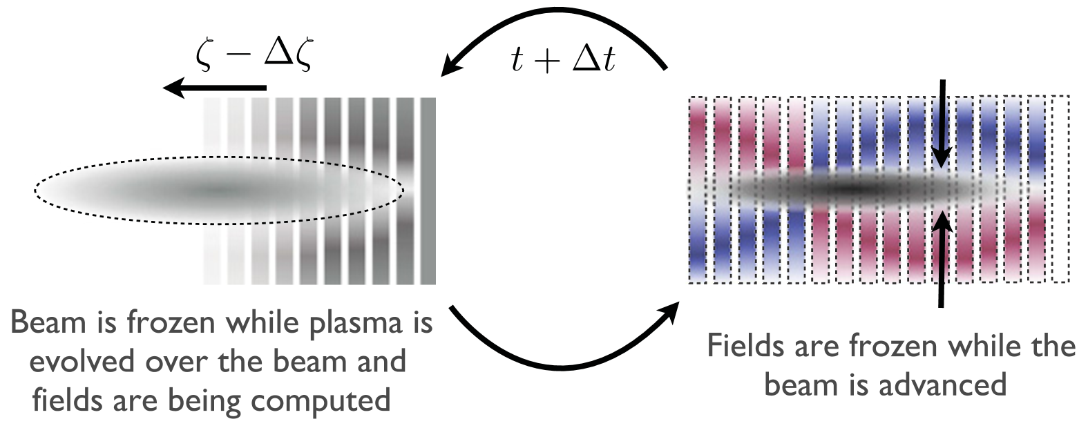
Reduced dimensionality is another important approximation. Early PIC codes used for the very first PWFA simulations, such as WAVE [348] and ZOHAR [264], simulated only one or two spatial dimensions, in a Euclidian geometry. In order to simulate axisymmetric beams, which are more realistic, cylindrical symmetry was introduced, as in the codes LCODE [299] and INF&RNO [40]. A somewhat more sophisticated version of this is Fourier decomposition [280], as employed in FBPIC [272] and QPAD [275], whereby several azimuthal modes can be included to simulate the lowest-order moments of a transverse asymmetry.
If only small regions of the simulation grid require high resolution, it is possible to use adaptive mesh refinement [492]. This was first employed in the code Warp [189]. An updated version of this code, WarpX [494], as well as FBPIC and the quasistatic code HiPACE++ [114], were also early adopters of GPU acceleration, which provides a significant speedup compared to CPU operation.
Lastly, in order to study long-term evolution of the plasma after the passage of the beam (see Sec. III.4), some codes employ kinetic–fluid hybrid methods: modeling the beam as particles, but the plasma as a hydrodynamic fluid, with the associated limitation of not capturing kinetic plasma effects such as trajectory crossing (see Sec. II.1.3). Examples include the above-mentioned 2D codes LCODE and INF&RNO, as well as the 3D code Architect [318]. Another use of such hybrid methods is mixed dimensionality; by simplifying the description of the plasma even further, using models by Lu et al. [312] (1D) or Baxevanis and Stupakov [38] (2D), while maintaining a 3D beam, simulations can be very fast—the code Wake-T [144], which implements such a strategy, is currently one of the fastest codes for basic PWFA simulations.
IV.2 Experimental facilities and results
Since the inception of PWFA [74, 433], experimental test facilities have been planned and operated. Early beam–plasma experiments were performed in Soviet Ukraine [242, 137], but modern investigations began with those conducted in the United States by Rosenzweig et al. [428]. Results from facilities across the US, Japan and Europe are covered lab-by-lab in chronological order of first commissioning. For a general overview of experimental methods and diagnostics for plasma accelerators, see the review by Downer et al. [122].
IV.2.1 Argonne National Laboratory: AATF and AWA
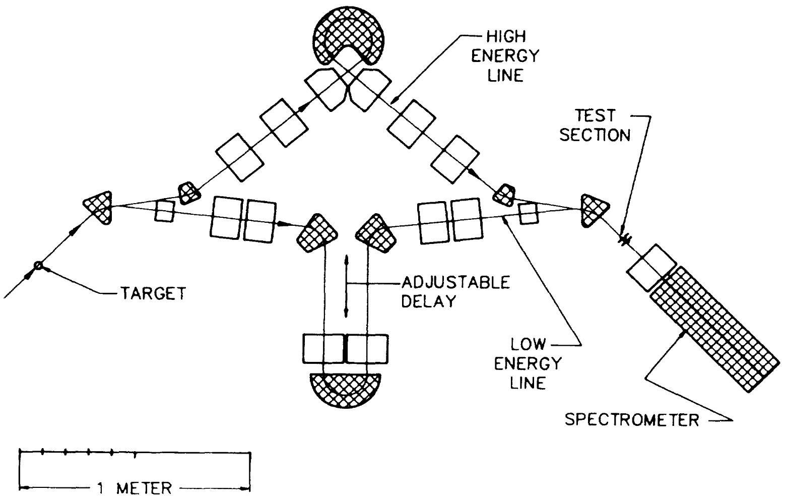
The first proof-of-principle demonstration of beam-driven plasma wakefields by Rosenzweig et al. [427] (see Fig. 4) was achieved at Argonne National Laboratory’s Advanced Accelerator Test Facility (AATF). Here (see Fig. 39), two bunches of energy 21 and were created by sending a small portion (transversely) of a single bunch through a carbon target, transporting the low- and high-energy bunches through separate beam lines—one with an adjustable “trombone” delay section—and combining them into a 20–-long hollow-cathode arc source filled with argon operating at a plasma density of 0.7– [422]. The driver had of charge and a length of rms. The observed wakefield, at around , agreed with the linear theory [74]. Later experiments with higher charge (2.9–) showed nonlinear steepening of the wakefields and a density perturbation of around [430]. Additionally, electron self-focusing, or passive plasma lensing, was observed [431].
Later, the Argonne Wakefield Accelerator (AWA) test facility, which provided low-energy () but high-charge beams (), was the first to reach the blowout regime [33] by producing a beam density () higher than the plasma density (). More recently, an emittance-exchange chicane was installed to shape the current profile, which was used to demonstrate a transformer ratio as high as 7.8 [432] (see Fig. 9 and Sec. II.1.4).
IV.2.2 KEK and Tokyo University
Early PWFA experiments were also performed in Japan [368] between 1989 and the mid-1990s at KEK and Tokyo University, discussed below. Related experiments were also conducted at Utsunomiya University using low-energy ion bunches [365].
The first experiments were performed at KEK [359] using the positron linac of the Photon Factory and TRISTAN Accumulation Ring, which could deliver electrons and positrons at . Six nC-level electron bunches spaced by were injected into a -long helicon source ionizing argon to a density of –. The plasma density was measured with a Langmuir probe, which also measured a temperature of 2–, while a streak camera and dipole spectrometer were used to measure the beam in longitudinal phase space. Accelerating fields higher than were observed, but the resonant build-up was not consistent with linear theory after the first three bunches, likely due to transverse misalignment of the later bunches.
Lower-energy experiments were performed at Tokyo University [360], using beams from two independent linacs operated at different energies (14–18 and 24–) combined into a similar plasma source as that described above. Early experiments, using only one beam, showed resonant buildup of the wakefield from a train of multiple bunches, measured with a coaxial diode, reaching 400 times the amplitude of a single bunch [370]. Twin-linac experiments were then performed, first in the overdense regime [371] and later in the underdense regime [372, 254], the latter showing hints of nonlinear behavior.
IV.2.3 Brookhaven National Laboratory: ATF
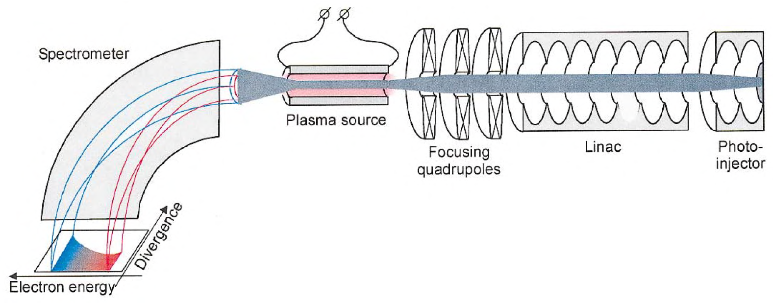
The Accelerator Test Facility (ATF) at Brookhaven National Laboratory, USA, performed PWFA experiments [396] using a high-quality electron beam from a photocathode. Initial experiments (see setup in Fig. 40), using a -long capillary-discharge plasma source [234], demonstrated that the accelerating and focusing fields had a phase offset of [540], as expected in the linear regime. The facility pioneered the use of collimator masks in energetically dispersive sections to generate bunches separated by picoseconds [539, 351] and was the first to use this technique for double-bunch plasma acceleration [235], showing a loaded accelerating field up to ( unloaded) at a plasma density of . Resonant excitation using multiple bunches was also demonstrated [353, 350]. Finally, experiments were performed that demonstrated a current-filamentation instability [13] as well as seeding of the self-modulation instability [140] (see Secs. II.2.4 and III.2).
IV.2.4 SLAC National Accelerator Laboratory: FFTB, FACET, and FACET-II
SLAC has hosted three beam test facilities that support PWFA research. The Final Focus Test Beam (FFTB) operated from 1993–2006 [63]. The Facility for Advanced Accelerator Tests (FACET) operated from 2011–2016 [82]. The successor to FACET, FACET-II, has been operating since 2020 [541]. Each of these facilities leverage the infrastructure that was built for the original SLAC complex, including electron and positron sources and the high energy linac. Additionally, PWFA research at SLAC greatly benefited from the construction of the Sub-Picosecond Photon Source (SPPS) chicane that was installed in the main linac to test bunch compression concepts for LCLS [42].
The FFTB PWFA program consisted of four experiments: E157, E162, E164 and E167. The experiments used meter-scale lithium vapor heat-pipe ovens [501] that were photo-ionized or beam-ionized to produce a plasma [352, 367]. The E157 experiment explored PWFA with the mm-long electron bunch [239, 23, 209, 83]. Results from E157 included the refraction and guiding of electron beams inside a plasma column [355, 354], matched beam propagation in plasma [356], and observation of x-ray betatron radiation from the plasma [512]. The E162 experiment replaced electron beams with positron beams. Results included positron transport through meter-scale plasmas [210], acceleration of positrons in plasma [46], and halo formation due to nonlinear focusing of positron beams in plasma [357].
The E164 and E167 experiments operated with shorter electron bunches which enabled the use of higher plasma densities and gradients. This led to the observation of multi-GeV energy gain [211] and eventually the energy-doubling result [48] (see Fig. 5). Additional results include positron generation from betatron radiation [228] and ionization injection of bright bunches [378, 247].
The FFTB program ended with the construction of LCLS, which only required the final kilometer of the SLAC linac for operation. Based on the success of the FFTB PWFA program, FACET was proposed as a user facility to host accelerator R&D with a specific emphasis on PWFA research [82]. FACET added a variable chicane at the end of the linac to provide additional compression and control of the longitudinal bunch profile. The final chicane included a notch collimator in a dispersive region that was used to convert a single bunch to two bunches with -scale separation—much smaller than the rf bucket spacing. FACET was also capable of running with compressed positron bunches and included a Ti:Sapphire laser used to pre-ionize the plasma source [186].
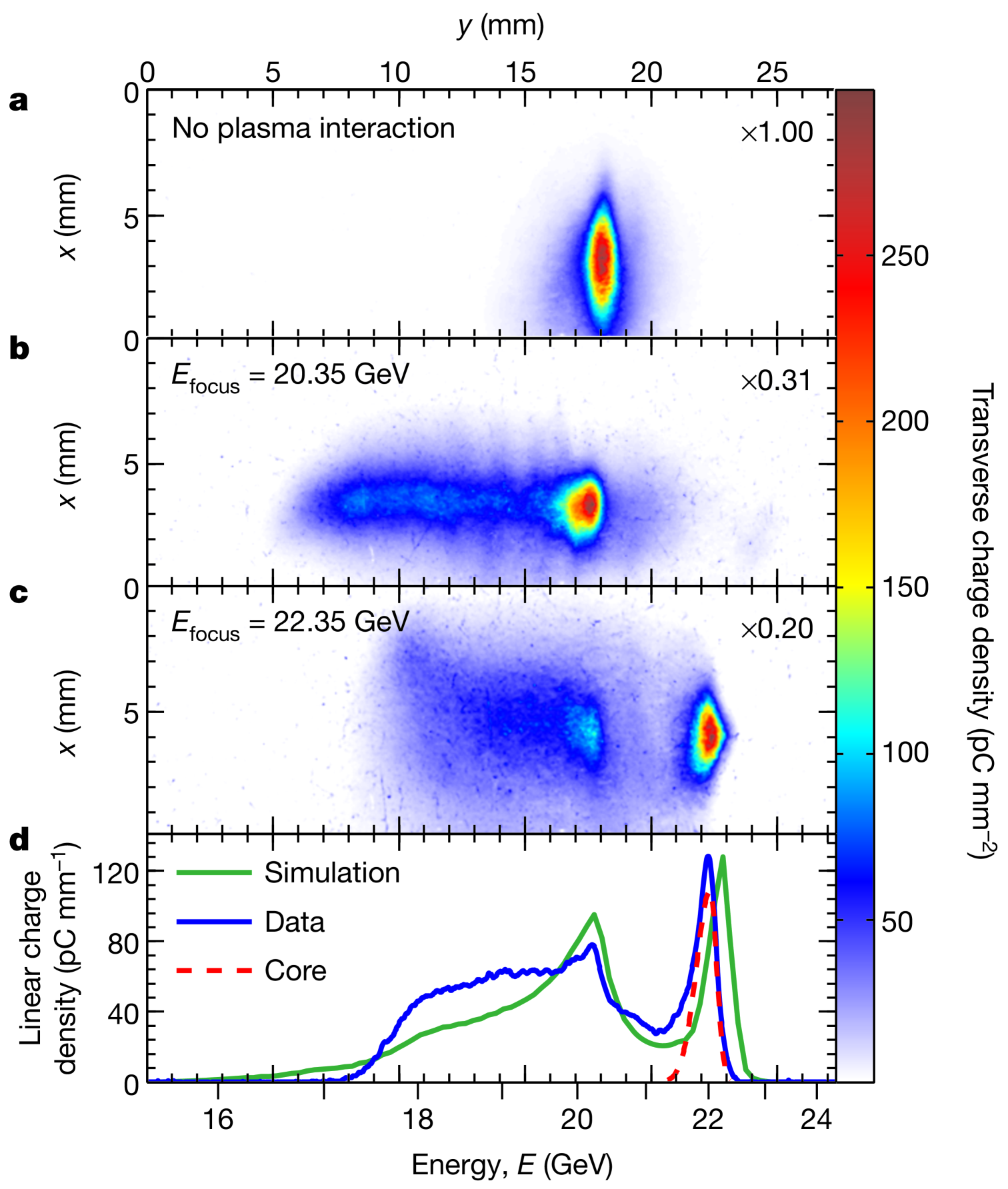
The E200 experiment [212] demonstrated high energy-transfer efficiency PWFA [292], with efficiencies as high as 30% with energy gain (see Fig. 41). With a longer oven, the energy gain was raised to [293]. FACET also demonstrated the acceleration of low-energy spread positron bunches [89] [see Fig. 18(c)], two-bunch positron acceleration [118], and a positron beam-driven hollow-channel plasma accelerator [166] (see Sec. III.1.2 and Fig. 28). Further results on hollow-channel positron acceleration included the measurement of transverse wakefields [288] (Fig. 29) and acceleration of a trailing positron bunch in the channel [168].
The wider E200 program included beam physics [85, 4] and high-field acceleration studies [90]. A number of ionization-injection experiments were pursued at FACET [487, 488, 489], including the plasma photocathode [109] (see Sec. III.3 and Fig. 33). Novel techniques to measure the long-term evolution of the plasma using an oblique-angle laser probe helped to determine the lifetime and energy deposited in the plasma [546] (see Sec. III.4).
The FACET program ended in 2016 to allow the re-purposing of the first third of the SLAC linac for the LCLS-II superconducting rf FEL. The facility concept for FACET-II [541] replicates the LCLS normal-conducting rf design [134]. The normal-conducting rf photocathode gun provides short, low-emittance electron beams. The cathode laser may be double pulsed to provide two electron bunches in the same rf bucket. This level of control was not possible with damping-ring sources at FACET. FACET-II is capable of producing extremely high peak-current beams, which can be diagnosed in part through their interactions with the plasma [549, 127]. Experiments include E300 [233, 467], which aims to demonstrate controlled two-bunch acceleration with high overall efficiency (see Sec. II.3.1) and beam-quality preservation (see Sec. II.3.2).
IV.2.5 CERN: AWAKE
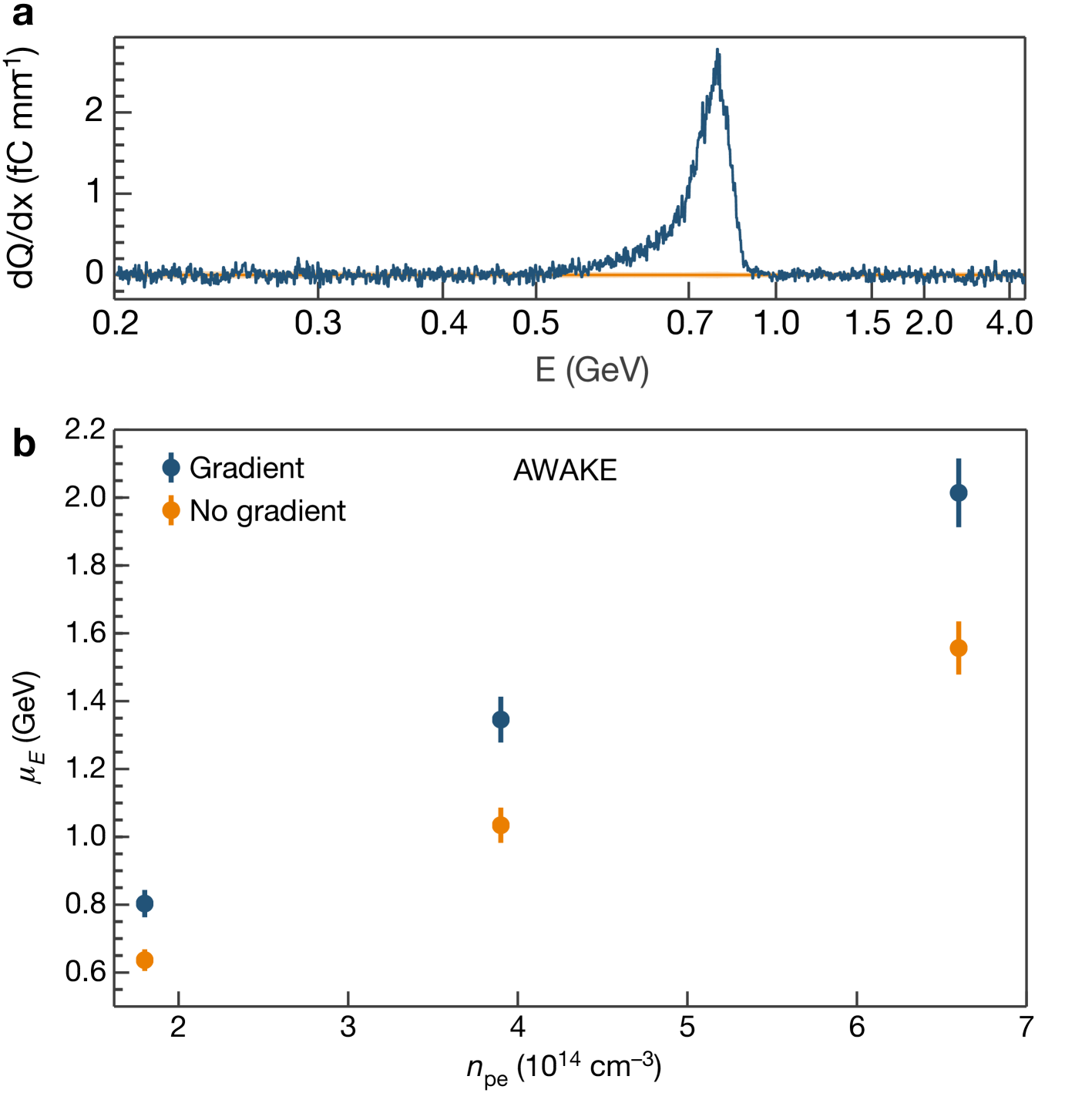
The AWAKE facility at CERN is the world’s only proton-beam-driven PWFA facility [24, 68, 191, 358], using protons from the SPS delivered 2–4 times per minute. It occupies the tunnel formerly used by the CNGS neutrino experiment [190]. AWAKE has an electron beamline producing bunches with ps bunch length [388, 243] used for external injection into a self-modulated wakefield (see Sec. III.2). The experiment employs a unique, laser-ionized [107] -long rubidium plasma source [377, 394]. Diagnostic systems include streak cameras [418], beam-halo monitors [480], and an electron-energy spectrometer [36].
AWAKE demonstrated acceleration of electrons in a proton beam-driven plasma wakefield up to [6, 193] (see Fig. 42 and Sec. III.2.2). Subsequent studies mapped the strength of the self-modulated wakefield by scanning both the timing of the laser seed pulse that creates the relativistic ionization front and the timing of the injected electron bunch [482, 72]. The facility is also well suited to measuring fundamental plasma-physics processes, using its long plasma source and unique suite of diagnostics. Measurements include observation of proton-bunch hosing [361] (see Sec. II.2.3), observation of transverse filamentation [499] (see Sec. II.2.4), and the effect of ion motion on wake formation [483].
An upgrade of the AWAKE facility is planned [194], making space for longer plasma cells. The plasma cell will be split into a modulation stage and an acceleration stage, between which electrons are injected—higher electron energy is used in order to increase the charge-capture efficiency [410]. The upgraded facility will feature novel, extendable plasma sources such as helicon plasma cells [65].
IV.2.6 INFN: SPARC_LAB and EuPRAXIA
The SPARC_LAB facility [148]—the result of the PLASMONX project [12]—is located at INFN in Frascati, Italy, and builds on the existing SPARC accelerator and FEL facility [11]. It uses a electron rf accelerator with velocity bunching to perform PWFA experiments. Multi-bunch generation is based on comb-like laser pulses directly on the photocathode [147, 81]. A set of permanent magnetic quadrupoles provides compact final focusing into the plasma [399]. The plasma source, used for PWFA as well as for active-plasma-lens experiments [319, 399], is a -long 3D-printed discharge capillary [151], characterized using optical spectroscopy [91].
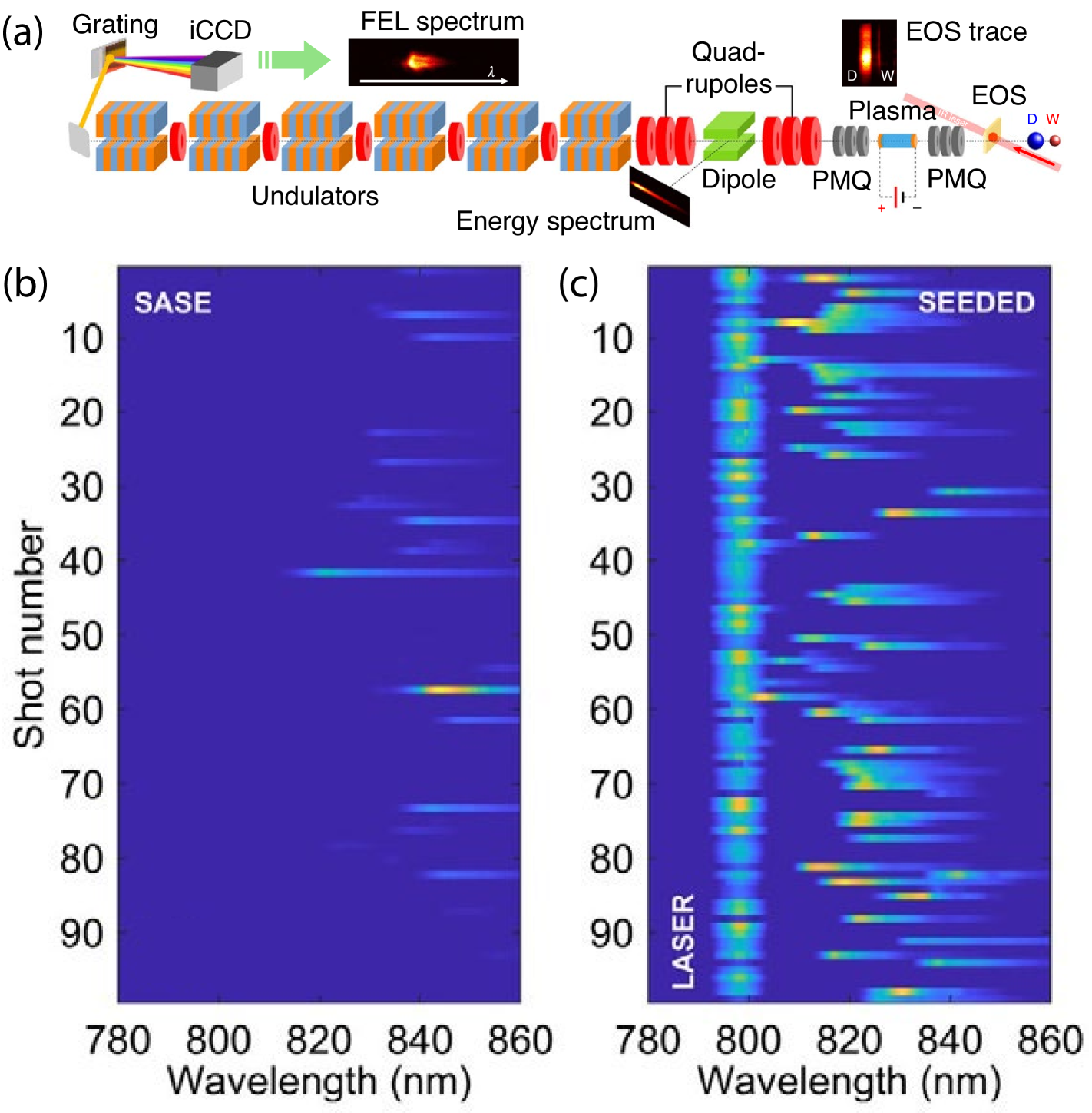
Early experiments included reduction of energy spread, either through dechirping of a single bunch [459] or using a double-bunch setup where the dechirped bunch was also accelerated [400]. First emittance measurements were also performed, using a multi-shot quadrupole scan [460]. A seminal result was the use of the PWFA module to boost the energy of a high-quality bunch, from 88 to , before using it in an FEL application; the quality was sufficiently preserved to demonstrate FEL gain [401]. This experiment included seeding of the FEL process with an infrared laser [163] (see Fig. 43). Recent experiments include the use of an integrated plasma source with upstream and downstream plasma lenses for improved matching [403], measurements of ns-scale recovery of the plasma density in hydrogen [402], and observation of plasma screening of relativistic beam fields [500].
IV.2.7 DESY: PITZ and FLASHForward
Two separate facilities have been performing PWFA experiments at the Deutsches Elektronen-Synchrotron (DESY) in Germany: PITZ at the Zeuthen site and FLASHForward at the Hamburg site.
The PITZ facility [187], dedicated to photo-injector research, delivers fairly long electron bunches () at energies up to . An -long heat-pipe oven was used to create a lithium plasma, ionized by a UV laser, in the density range . Two key experimental results were achieved: first demonstration of the self-modulation instability, measured in longitudinal phase space using a combination of an rf deflector and a magnetic dipole [188]; and the first demonstration of high transformer ratios (see Sec. II.1.4), up to 4.6, by employing a long driver with ramped current profile [296]. Later work includes the development of low-jitter discharge-based plasma sources [298].
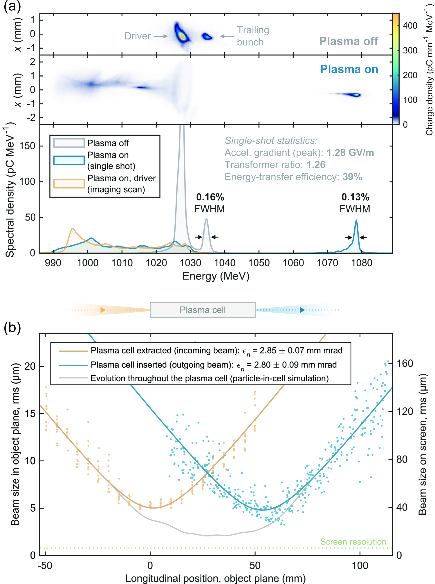
The FLASHForward facility [21, 100] makes use of , electron bunches accelerated in the FLASH linac, a free-electron laser facility based on superconducting rf cavities and a high-quality photocathode electron source. The experimental area includes a collimator system for double-bunch generation [443], a capillary-based plasma source, ionized by either a Ti:sapphire laser or a high-voltage discharge, an imaging-spectrometer setup with both broadband and high-resolution screens, and a polarizable transverse-deflection structure [180] for measuring the longitudinal phase space. The facility is unique in its ability to deliver bunches at up to repetition rate and, in principle, up to of beam power. Three major directions have been pursued: downramp injection for beam-brightness transformation (Sec. III.3.2), external injection with beam-quality preservation and high energy-transfer efficiency (Sec. II.3), and experiments investigating the limits of repetition rate (Sec. III.4).
Initial experiments at FLASHForward included a demonstration of dechirping [101] (see Fig. 21), in which the energy spread of a bunch was reduced from 1.31% to 0.33% FWHM in a -long plasma; high-resolution measurements of plasma wakefields [444] based on collimation; and a novel BPM-based diagnostics technique for measuring small beta functions [286]. Stable density-downramp injection was achieved [251] [see Fig. 34(d)], with a 95% injection probability and a normalized emittance of for the injected electron bunch. Optimal beam loading was demonstrated [290] [see Fig. 20(a)], showing simultaneous high energy-transfer efficiency of and preservation of 0.16% FWHM energy spread, followed by demonstration of emittance preservation at with energy gain [291], shown in Fig. 44(a) and (b), respectively. High driver-energy depletion was also demonstrated with [387] (Fig. 15 and Sec. II.2.5). The longitudinal phase space of beam-loaded bunches was measured for the first time [see Figs. 20(c–e)], which was used to set a new upper bound on the transverse uniformity of accelerating field observed inside the plasma wake: 0.6% rms at 68% confidence level [179]. Limits on repetition rate in PWFA were also established [102], indicating that long-term ion motion requires at least 10– (in argon) before repeatable acceleration is recovered (see Fig. 36).
IV.2.8 Hybrid LWFA-driven PWFA
LWFA can generate electron bunches that are suitable for driving the PWFA process. A transition from laser-driven to beam-driven plasma waves can naturally happen in LWFA when the laser driver depletes and the accelerated electron bunch takes the role of a driver. This has been observed in early numerical studies [479, 379], and several experimental studies found indications for this transition [88, 328, 200, 196].
A hybrid acceleration scheme, where LWFA is used specifically to generate PWFA drivers, is depicted in Figs. 45(a–c). The concept was proposed as an energy booster for LWFA [204], but it soon became apparent that its prospects are much broader [see e.g. Hidding et al. [206, 203]]. The hybrid scheme allows to utilize the strengths of both LWFA and PWFA, i.e., the availability, compactness and comparatively low cost of LWFAs, and the prospects of high beam qualities from PWFAs. Such hybrid accelerators may then be used, e.g., as compact and low-cost drivers for FELs (see Sec. V.2). Hybrid LWFA–PWFA can also open new opportunities for ultrabright gamma-ray sources, which can be obtained from betatron radiation [512] in a high-density PWFA driven by an electron beam generated in a low-density LWFA [150].
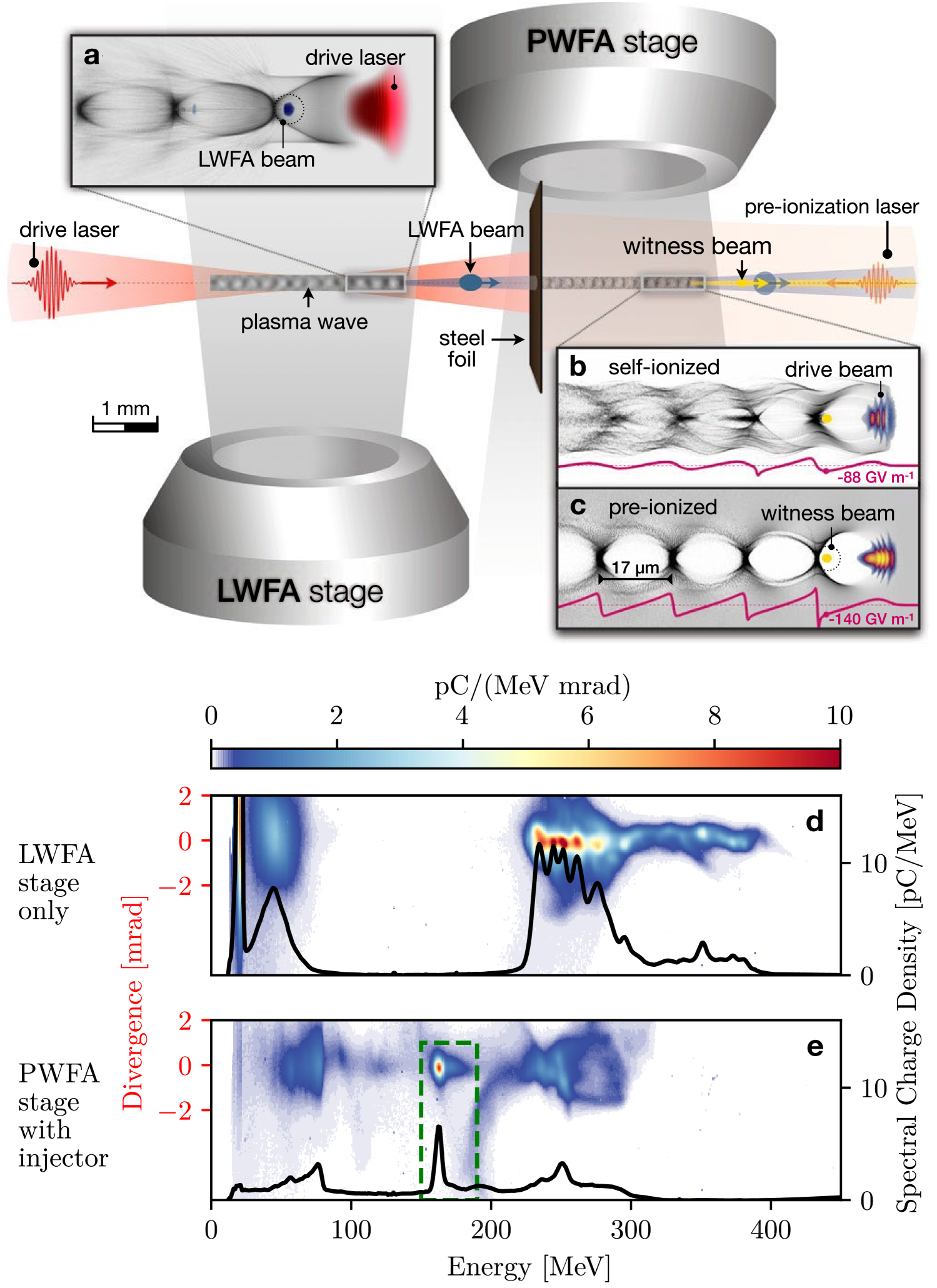
Experimental progress in hybrid LWFA-driven PWFA, reviewed by Hidding et al. [207], has mainly been driven by three facilities: (i) the Laboratory for Extreme Photonics (LEX) at the Ludwig-Maximilians-Universität München with the ATLAS 300 laser (until 2016); (ii) the Helmholtz-Zentrum Dresden-Rossendorf (HZDR) with the -class DRACO laser; and (iii) the Centre for Advanced Laser Applications (CALA) at the Ludwig-Maximilians-Universität München with the upgraded ATLAS 3000 laser (from 2017).
Proof-of-principle experiments demonstrated that PWFA can be powered by LWFA-generated electron bunches, by observing plasma lensing [262] and deceleration [80] of the drive electron bunch and the acceleration of a trailing electron bunch [261] in the PWFA stage, and by taking the first snapshots of PWFA plasma waves [172] (see Fig. 35). Shortly after, internal injection based on density-downramp injection (see Sec. III.3.2) in the PWFA stage and subsequent acceleration have been achieved in two different laboratories [93, 155]. Foerster et al. [155] showed that the hybrid scheme can act as a quality transformer, where lower-quality LWFA beams can generate higher-quality electron beams in the PWFA process [see Figs. 45(d–e)].
The hybrid scheme also enables fundamental PWFA research in widely available laser laboratories, which can support the research towards large-scale high-energy accelerators and colliders (see Sec. V.1). Götzfried et al. [184] used a pair of electron bunches from LWFA to study PWFA with a two-bunch configuration. Schöbel et al. [454] observed the damping of PWFA plasma waves in a self-ionized plasma (i.e., an initially neutral gas ionized by the fields of the drive electron beam) and the elongation of the first PWFA plasma period with higher PWFA drive charge. The inherently synchronized laser that drives the LWFA can easily be used for optical diagnostics like few-cycle shadowgraphy [59, 453, 439]. This allowed, e.g., to study the long-term plasma response with high spatial and temporal resolution [172] (see Sec. III.4). This inherent synchronization facilitates advanced concepts of internal injection that require an additional laser to trigger injection, e.g. the plasma-photocathode scheme (see Sec. III.3.1).
V Applications
Beam-driven PWFA has historically been motivated by the potential to shrink the footprint and cost of large-scale and high-power particle accelerators, such as those used for high-energy physics and photon science. This most prominently includes particle colliders (Sec. V.1) and free-electron lasers (Sec. V.2), as detailed below, but also other applications such as fixed-target experiments [526], synchrotron injectors [517] and potentially strong-field QED experiments [86, 395, 339, 329].
V.1 Particle colliders
The concept of PWFA emerged from basic research on laser–plasma [472] and beam–plasma interactions [74, 433], but it was immediately recognized by the high-energy physics community as a promising technology for future colliders at the TeV scale [417, 231].
The first conceptual design of a collider based on beam-driven plasma accelerators was introduced by Rosenzweig et al. [420, 421], as shown in Fig. 46(a). It was based on one low-gradient () and high-power () rf linac providing electron drivers for two PWFA linacs, each with multiple -long stages accelerating at . This collider concept was envisioned as a gamma–gamma collider [173], where both arms accelerate electron beams converted to photon beams shortly before the interaction point.
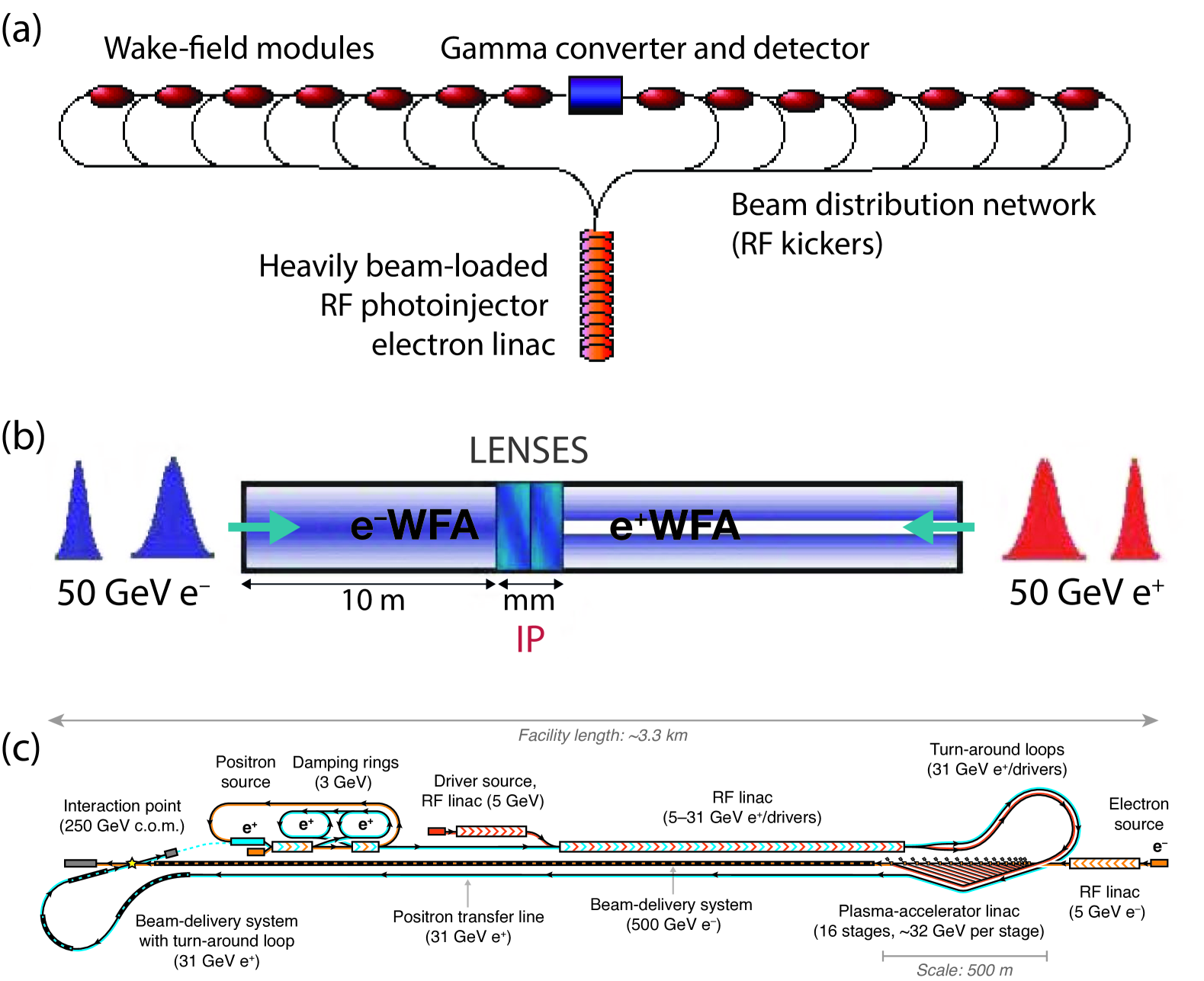
The next concept to be introduced was the “plasma afterburner” or “energy doubler” [270] [see Fig. 46(b)]. This uses beams from an existing linear collider, splits them longitudinally into two bunches, doubling the energy of the trailing bunch just prior to the interaction point. It was also proposed to use hollow channels for positrons (see Sec. III.1.2) and plasma lenses for final focusing [73]. The original study used beams from the Stanford Linear Collider, but was later extended to beams from ILC [412], inspiring studies into the detrimental effect of ion motion [429] (see Sec. II.3.2). A multi-bunch version of the afterburner concept was proposed by Maeda et al. [314], using up to five unequally spaced drivers to give higher energy gain (2.8 the initial energy) and lower energy spread (4%).
A new iteration of the multistage collider, colliding electrons and positrons, was proposed by Seryi et al. [456], Pei et al. [385], as shown in Fig. 2. Inspired by CLIC [9], it fleshed out the rf driver linac design, beam loading (Sec. II.3.1), and the driver-distribution system using kickers and 180-degree turn-arounds. An updated version was later introduced by Adli et al. [2], Delahaye et al. [106], who simplified the driver-distribution system with an undulating chicane design instead of turn-arounds. This version was estimated to reach a wall-plug energy efficiency of approximately 10% and a similar luminosity-per-power [Eq. (52)] to that of CLIC. However, it also focused a spotlight on the challenge of high-quality positron acceleration [70] (see Sec. III.1) as well as compact, quality-preserving staging (see Sec. III.5), which remained unsolved in these designs [7].
The hybrid, asymmetric, linear Higgs factory (HALHF) concept by Foster et al. [157] sidesteps the positron problem by only accelerating electrons with PWFA (to high energy), colliding them with positrons accelerated by an rf accelerator (to lower energy), as illustrated in Fig. 46(c). HALHF initially proposed to collide electrons with positrons, resulting in a center-of-mass energy; an updated baseline [158] uses 375 and , respectively. Asymmetric collisions requires more energy overall, as the collision products have a forward boost, but this can be re-couped by using asymmetric bunch charges: more charge in the low-energy positrons and less in the high-energy electrons. Moreover, the higher electron energy allows for a higher normalized emittance (but similar geometric emittance) in the PWFA linac, which mitigates issues such as transverse tolerances (see Sec. II.3.2) and ion motion (see Sec. II.3.2). Cost estimates obtained by scaling from ILC and CLIC showed significant cost savings compared to rf-only-based colliders [8]. As with previous concepts, more realism in design leads to new specific challenges, including plasma heating and cooling (see Sec. III.4), as well as cross-plane emittance mixing of flat beams [113].
While all the above concepts used electron drivers, proton-driven collider concepts have also been proposed. One concept is the very high energy electron–proton collider (VHEeP) proposed by Caldwell and Wing [67], using protons from the LHC to accelerate electrons up to in a self-modulated wake (Sec. III.2) colliding with another LHC proton beam. Specifically, this could reach parton momentum fractions, , down to for photon virtualities, , of . Another concept is the plasma electron–proton/ion collider (PEPIC) [192], siphoning off LHC beams to a proton-driven PWFA to produce and re-inject electrons into the LHC for – collisions. Lastly, an electron–positron collider based on PWFA driven by short proton bunches was recently proposed by Farmer et al. [141], utilizing fast-ramping proton rings.
V.2 Free-electron lasers
In photon science, which makes use of bright photon beams for research in e.g. biology, chemistry, and material science [52], PWFAs can open new possibilities with the application of a plasma-based free-electron laser. Recently, FELs powered by plasma accelerators saw their first real-world demonstrations, for both LWFA [515, 263] and PWFA [401, 163], successfully operating in either self-amplified spontaneous emission (SASE) or seeded configurations (see Fig. 43). These experimental breakthroughs represent a cornerstone in the development of photon-science applications of plasma accelerators, opening prospects for both more compact FELs and higher photon brightness [125, 162], as discussed below.
PWFA offers several avenues for reducing the size and cost of FELs. A standard quality-preserving PWFA module can be used as a cost-effective energy booster or upgrade for the FEL electron beam driver, which can be of interest to existing FEL facilities [220, 442] as well as new facilities, e.g. EuPRAXIA [25]. In the latter case, the PWFA “pillar” of EuPRAXIA uses a 0.5– driver and trailing bunch from an X-band linac [486] to reach 1– after the PWFA stage, lasing in the undulators at a wavelength of a few nm [149, 390]. Looking ahead, PWFA R&D may allow use of high-transformer ratio (see Sec. II.1.4) or multistage acceleration (see Sec. III.5) to extend the energy reach beyond what a standard PWFA module can provide. Ultimately, this could enable x-ray FELs (XFELs) [386] with electron drivers in the 10– range with a total accelerator length (i.e., rf linac and PWFA) of less than , comparable or shorter than the undulator section. Finally, plasmas or lasers can themselves be used as compact undulators, replacing magnetic undulators by a “plasma wiggler” in the so-called ion-channel laser [524, 131, 103] or by an optical undulator [536].
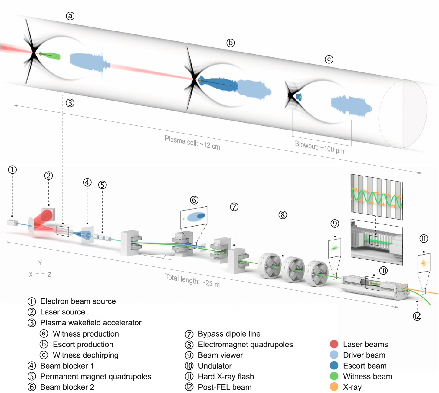
The other key motivation, with a potentially strong physics impact, comes from the new capabilities opened by ultrabright and ultrashort beams from PWFA. Internal injection (Sec. III.3) in PWFA offers new means to generate beams of superior brightness, e.g. using the plasma photocathode scheme [205] that can deliver 6D brightness [Eq. (51)] of [316, 198], as well as pre-bunched beams [535]. Beams internally injected and accelerated in a PWFA are generally chirped (see Sec. II.3.1) and can be further compressed to attosecond duration and near-MA currents in a magnetic chicane [124, 202]. Alternatively, an externally injected trailing bunch from the linac can be chirped in a PWFA stage for further compression to near-MA currents [126]. These unique beam properties enable novel possibilities with near-single-spike temporally coherent FEL radiation pulses with duration of the order of FWHM or below and GW-to-TW peak power. In addition, higher brightness and beam current lead to much reduced FEL gain length, resulting in a more compact undulator section [37]. For example, in the conceptual design depicted in Fig. 47, the plasma photocathode, beam transport and undulators fit in a total length of while delivering attosecond and angstrom FEL light [198].
Combining the above advantages of PWFA, a very competitive PWFA-based FEL facility design was proposed by Hogan [208] (see Fig. 17 therein), leveraging high-repetition-rate beam drivers to drive multiple FELs, high-transformer-ratio PWFA for compact acceleration, and plasma photocathode for compact undulators and for single-spike attosecond FEL light whose photon brightness exceeds the current state-of-the-art. An alternative design for a compact FEL relies on hybrid LWFA-driven PWFA (see Sec. IV.2.8), which benefits from the beam quality offered by PWFA, the compactness and comparatively low cost of LWFA, and the inherently precise synchronization between lasers and beams that originate from a single laser system.
VI Conclusion and outlook
The field of beam-driven plasma acceleration is currently witnessing extraordinary progress. Collaborative efforts among national laboratories and university research groups have successfully merged diverse expertise in accelerators, lasers, plasmas, and computational methodologies, resulting in pioneering experiments at state-of-the-art accelerator test facilities. Recent workshops [129, 349] have culminated in comprehensive roadmaps that prioritize essential areas such as emittance preservation, effective staging, and the operation of systems capable of delivering high average beam power.
At a basic level, an accelerator is a power source and an accelerating structure. In PWFA, the power source is a high-energy particle beam, and the structure is a plasma. The ongoing development of high-quality, high-power, high-energy electron beams at facilities like the European XFEL and LCLS-II, coupled with the ability of plasmas to sustain GV/m accelerating fields and MT/m focusing gradients, positions the PWFA community at the forefront of accelerator R&D. These advances enable the acceleration of high-brightness electron beams, potentially adding GeVs of energy while preserving beam quality. As we strive for brighter electron beams, we unlock the potential for enhanced photon generation, opening new avenues for applications in photon science.
Future endeavors in the medium term likely involve the implementation of multi-stage plasma accelerators to achieve energies of order . Achieving these energy levels will enable forefront studies into strong-field quantum electrodynamics [283] or high-energy-physics studies including precision quantum chromodynamics and Beyond the Standard Model physics measurements [61]. Furthermore, the most ambitious concepts envisage employing plasmas to drastically reduce the size, cost, and carbon footprint associated with colliders examining the Higgs boson and subsequently the energy frontier of particle physics. In this context, plasma serves as a compact energy transformer, converting, e.g., a , beam into a , beam for high-energy-physics applications. However, these exciting opportunities are accompanied by challenges in areas such as cell heating, staging and emittance preservation that require new solutions to ensure competitive luminosity and power efficiency.
The conceptual frameworks articulated in this Review not only illustrate the immense potential of PWFA but also highlight critical research priorities. Notable design initiatives, such as EuPRAXIA [25], HALHF [157, 158], and the ongoing study of a parton center-of-momentum wakefield-based energy frontier collider [165], will provide further guidance and focus for research directions and will identify needs for future R&D and demonstrator facilities. Continued progress in demonstrating plasma acceleration as a viable technology necessitates the establishment of robust test facilities for experimental validation of new theories and designs. Moreover, the development of advanced simulation capabilities, integrating reduced models, artificial intelligence and machine learning surrogates, and exascale computing, will be vital for exploring the vast available parameter space, optimizing performance, and determining tolerance metrics.
This is an exhilarating era for plasma-wakefield accelerator research, marked by the promise of groundbreaking applications and theoretical refinement. The coming years are poised to yield further discoveries and the first realization of practical applications, leading to refined concepts for light sources and energy-frontier colliders. As the field continues to evolve, it is set to significantly impact high-energy physics and beyond, driving advances in both scientific inquiry and technological innovation.
Acknowledgements.
The authors would like to thank B. Foster for valuable feedback. This work was funded by the Research Council of Norway (NFR Grant No. 313770) and the European Research Council (ERC Grant Agreement No. 715807 and No. 101116161). This work was supported in part by the Director, Office of Science, Office of High Energy Physics, of the U.S. Department of Energy, under contract numbers DE-AC02-76SF00515 and DE-AC02-05CH11231.References
- Abbott et al. [2016] Abbott, D, et al. (PEPPo Collaboration) (2016), Phys. Rev. Lett. 116, 214801.
- Adli et al. [2013] Adli, E, J.-P. Delahaye, S. J. Gessner, M. J. Hogan, T. Raubenheimer, W. An, C. Joshi, and W. Mori (2013), arXiv:1308.1145 .
- Adli and Muggli [2016] Adli, E, and P. Muggli (2016), Rev. Accel. Sci. Tech. 9, 85–104.
- Adli et al. [2016a] Adli, E, et al. (2016a), New J. Phys. 18, 103013.
- Adli et al. [2016b] Adli, E, et al. (2016b), Nucl. Instrum. Methods Phys. Res. A 829, 94–98.
- Adli et al. [2018] Adli, E, et al. (AWAKE Collaboration) (2018), Nature (London) 561, 363–367.
- Adli et al. [2019] Adli, E, et al. (AWAKE Collaboration) (2019), Phys. Rev. Lett. 122, 054802.
- Adli et al. [2025] Adli, E, et al. (HALHF Collaboration) (2025), arXiv:2503.19880 .
- Aicheler et al. [2012] Aicheler, M, et al. (2012), CERN Yellow Reports: Monographs No. CERN-2012-007 (CERN, Geneva, Switzerland).
- Akhiezer and Polovin [1956] Akhiezer, A I, and R. V. Polovin (1956), J. Exp. Theor. Phys. (U.S.S.R.) 3, 696–705.
- Alesini et al. [2003] Alesini, D, et al. (2003), Nucl. Instrum. Methods Phys. Res. A 507, 345–349.
- Alesini et al. [2005] Alesini, D, et al. (2005), in Proceedings of the 2005 Particle Accelerator Conf. (IEEE) pp. 820–822.
- Allen et al. [2012] Allen, B, V. Yakimenko, M. Babzien, M. Fedurin, K. Kusche, and P. Muggli (2012), Phys. Rev. Lett. 109, 185007.
- Amorim et al. [2023] Amorim, L D, C. Benedetti, S. S. Bulanov, D. Terzani, A. Huebl, C. B. Schroeder, J.-L. Vay, and E. Esarey (2023), Plasma Phys. Control. Fusion 65, 085016.
- An et al. [2017] An, W, W. Lu, C. Huang, X. Xu, M. J. Hogan, C. Joshi, and W. B. Mori (2017), Phys. Rev. Lett. 118, 244801.
- An et al. [2013] An, W, et al. (2013), Phys. Rev. ST Accel. Beams 16, 101301.
- Andreev et al. [1996] Andreev, N E, S. S. Bychkov, V. V. Kotlyar, L. Ya. Margolin, L. N. Pyatnitskii, and P. G. Serafimovich (1996), Quantum Electron. 26, 126–130.
- Antici et al. [2012] Antici, P, et al. (2012), J. Appl. Phys. 112, 044902.
- Antipov et al. [2014] Antipov, S, S. Baturin, C. Jing, M. Fedurin, A. Kanareykin, C. Swinson, P. Schoessow, W. Gai, and A. Zholents (2014), Phys. Rev. Lett. 112, 114801.
- Ariniello et al. [2019] Ariniello, R, C. E. Doss, K. Hunt-Stone, J. R. Cary, and M. D. Litos (2019), Phys. Rev. Accel. Beams 22, 041304.
- Aschikhin et al. [2016] Aschikhin, A, et al. (2016), Nucl. Instrum. Methods Phys. Res. A 806, 175–183.
- Assmann and Yokoya [1998] Assmann, R, and K. Yokoya (1998), Nucl. Instrum. Methods Phys. Res. A 410, 544–548.
- Assmann et al. [1998] Assmann, R, et al. (1998), Nucl. Instrum. Methods Phys. Res. A 410, 396–406.
- Assmann et al. [2014] Assmann, R, et al. (2014), Plasma Phys. Control. Fusion 56, 084013.
- Assmann et al. [2020] Assmann, R, et al. (2020), Eur. Phys. J. Spec. Top. 229, 3675–4284.
- Balakin et al. [1983] Balakin, V E, A. V. Novokhatsky, and V. P. Smirnov (1983), in 12th Int. Conf. on High-Energy Accelerators, HEACC, Vol. 830811 (Fermilab, Batavia, IL, United States) pp. 119–120.
- Bane et al. [1985a] Bane, K L F, Pisin Chen, and P. B. Wilson (1985a), IEEE T. Nucl. Sci. 32, 3524–3526.
- Bane et al. [1985b] Bane, K L F, P. B. Wilson, and T. Weiland (1985b), in AIP Conf. Proc., Vol. 127 (AIP) pp. 875–928.
- Barber et al. [2017] Barber, S K, et al. (2017), Phys. Rev. Lett. 119, 104801.
- Bargmann et al. [1959] Bargmann, V, L. Michel, and V. L. Telegdi (1959), Phys. Rev. Lett. 2, 435–436.
- Barov et al. [1998] Barov, N, M. E. Conde, W. Gai, and J. B. Rosenzweig (1998), Phys. Rev. Lett. 80, 81–84.
- Barov and Rosenzweig [1994] Barov, N, and J. B. Rosenzweig (1994), Phys. Rev. E 49, 4407–4416.
- Barov et al. [2000] Barov, N, J. B. Rosenzweig, M. E. Conde, W. Gai, and J. G. Power (2000), Phys. Rev. ST Accel. Beams 3, 011301.
- Barov et al. [2004] Barov, N, J. B. Rosenzweig, M. C. Thompson, and R. B. Yoder (2004), Phys. Rev. ST Accel. Beams 7, 061301.
- Batsch et al. [2021] Batsch, F, et al. (AWAKE Collaboration) (2021), Phys. Rev. Lett. 126, 164802.
- Bauche et al. [2019] Bauche, J, et al. (2019), Nucl. Instrum. Methods Phys. Res. A 940, 103–108.
- Baxevanis et al. [2017] Baxevanis, P, M. J. Hogan, Z. Huang, M. Litos, B. O’Shea, T. O. Raubenheimer, J. C. Frisch, G. White, X. L. Xu, and W. Mori (2017), in AIP Conf. Proc., Vol. 1812 (AIP) p. 100013.
- Baxevanis and Stupakov [2018] Baxevanis, P, and G. Stupakov (2018), Phys. Rev. Accel. Beams 21, 071301.
- Benedetti et al. [2021] Benedetti, C, T. J. Mehrling, C. B. Schroeder, C. G. R. Geddes, and E. Esarey (2021), Phys. Plasmas 28, 053102.
- Benedetti et al. [2010] Benedetti, C, C. B. Schroeder, E. Esarey, C. G. R. Geddes, and W. P. Leemans (2010), in AIP Conf. Proc., Vol. 1299 (AIP) pp. 250–255.
- Benedetti et al. [2017] Benedetti, C, C. B. Schroeder, E. Esarey, and W. P. Leemans (2017), Phys. Rev. Accel. Beams 20, 111301.
- Bentson et al. [2003] Bentson, L, P. Bolton, E. Bong, P. Emma, J. Galayda, J. Hastings, P. Krejcik, C. Rago, J. Rifkin, and C. M. Spencer (2003), Nucl. Instrum. Methods Phys. Res. A 507, 205–209.
- Beringer et al. [2012] Beringer, J, et al. (2012), Phys. Rev. D 86, 328.
- Bethe [1953] Bethe, H A (1953), Phys. Rev. 89, 1256–1266.
- Blachman and Courant [1948] Blachman, N M, and E. D. Courant (1948), Phys. Rev. 74, 140–144.
- Blue et al. [2003] Blue, B E, et al. (2003), Phys. Rev. Lett. 90, 214801.
- Blumenfeld [2009] Blumenfeld, I (2009), PhD Thesis (Stanford University).
- Blumenfeld et al. [2007] Blumenfeld, I, et al. (2007), Nature (London) 445, 741–744.
- Blumenfeld et al. [2010] Blumenfeld, I, et al. (2010), Phys. Rev. ST Accel. Beams 13, 111301.
- Bohlen et al. [2023] Bohlen, S, Z. Gong, M. J. Quin, M. Tamburini, and K. Põder (2023), Phys. Rev. Research 5, 033205.
- Bonatto et al. [2015] Bonatto, A, C. B. Schroeder, J.-L. Vay, C. G. R. Geddes, C. Benedetti, E. Esarey, and W. P. Leemans (2015), Phys. Plasmas 22, 083106.
- Bostedt et al. [2016] Bostedt, C, et al. (2016), Rev. Mod. Phys. 88, 015007.
- Braunmüller et al. [2020] Braunmüller, F, et al. (AWAKE Collaboration) (2020), Phys. Rev. Lett. 125, 264801.
- Bret et al. [2005] Bret, A, M.-C. Firpo, and C. Deutsch (2005), Phys. Rev. Lett. 94, 115002.
- Bret et al. [2010] Bret, A, L. Gremillet, and M. E. Dieckmann (2010), Phys. Plasmas 17, 120501.
- Brinkmann et al. [2017] Brinkmann, R, et al. (2017), Phys. Rev. Lett. 118, 214801.
- Brunetti et al. [2010] Brunetti, E, et al. (2010), Phys. Rev. Lett. 105, 215007.
- Buchanan [1987] Buchanan, H Lee (1987), Phys. Fluids 30, 221–231.
- Buck et al. [2011] Buck, A, M. Nicolai, K. Schmid, C. M. S. Sears, A. Sävert, J. M. Mikhailova, F. Krausz, M. C. Kaluza, and L. Veisz (2011), Nat. Phys. 7, 543–548.
- Bulanov et al. [1998] Bulanov, S, N. Naumova, F. Pegoraro, and J. Sakai (1998), Phys. Rev. E 58, R5257–R5260.
- Bulanov et al. [2024] Bulanov, S S, et al. (2024), J. Instrum. 19, T01010.
- Bulanov et al. [1997] Bulanov, S V, F. Pegoraro, A. M. Pukhov, and A. S. Sakharov (1997), Phys. Rev. Lett. 78, 4205–4208.
- Burke [1991] Burke, D (1991), in Proceedings of the 1991 Particle Accelerator Conf. (IEEE) p. 2055–2057.
- Butler et al. [2002] Butler, A, D. J. Spence, and S. M. Hooker (2002), Phys. Rev. Lett. 89, 185003.
- Buttenschön et al. [2018] Buttenschön, B, N. Fahrenkamp, and O. Grulke (2018), Plasma Phys. Control. Fusion 60, 075005.
- Caldwell et al. [2009] Caldwell, A, K. Lotov, A. Pukhov, and F. Simon (2009), Nat. Phys. 5, 363–367.
- Caldwell and Wing [2016] Caldwell, A, and M. Wing (2016), Eur. Phys. J. C 76, 463.
- Caldwell et al. [2016] Caldwell, A, et al. (AWAKE Collaboration) (2016), Nucl. Instrum. Methods Phys. Res. A 829, 3–16.
- Cao [2023] Cao, G J (2023), Instruments 7, 37.
- Cao et al. [2024] Cao, G J, C. A. Lindstrøm, E. Adli, S. Corde, and S. Gessner (2024), Phys. Rev. Accel. Beams 27, 034801.
- Chao [1993] Chao, A W (1993), Physics of collective beam instabilities in high-energy accelerators (Wiley).
- Chappell et al. [2021] Chappell, J, et al. (AWAKE Collaboration) (2021), Phys. Rev. Accel. Beams 24, 011301.
- Chen [1987] Chen, P (1987), Part. Accel. 20, 171–182.
- Chen et al. [1985] Chen, P, J. M. Dawson, R. W. Huff, and T. Katsouleas (1985), Phys. Rev. Lett. 54, 693–696.
- Chen et al. [1990] Chen, P, K. Oide, A. M. Sessler, and S. S. Yu (1990), Phys. Rev. Lett. 64, 1231–1234.
- Chen et al. [1986] Chen, P, J. J. Su, J. M. Dawson, K. L. F. Bane, and P. B. Wilson (1986), Phys. Rev. Lett. 56, 1252–1255.
- Cheshkov et al. [2000] Cheshkov, S, T. Tajima, W. Horton, and K. Yokoya (2000), Phys. Rev. ST Accel. Beams 3, 071301.
- Chiou and Katsouleas [1998] Chiou, T C, and T. Katsouleas (1998), Phys. Rev. Lett. 81, 3411–3414.
- Chiou et al. [1996] Chiou, T C, T. Katsouleas, and W. B. Mori (1996), Phys. Plasmas 3, 1700–1708.
- Chou et al. [2016] Chou, S, J. Xu, K. Khrennikov, D. E. Cardenas, J. Wenz, M. Heigoldt, L. Hofmann, L. Veisz, and S. Karsch (2016), Phys. Rev. Lett. 117, 144801.
- Cianchi et al. [2015] Cianchi, A, et al. (2015), Phys. Rev. ST Accel. Beams 18, 082804.
- Clarke et al. [2011] Clarke, C I, et al. (2011), in Proceedings of the 2nd Int. Particle Accelerator Conf. (JACoW, Geneva, Switzerland) pp. 1953–1955.
- Clayton et al. [2002] Clayton, C E, et al. (2002), Phys. Rev. Lett. 88, 154801.
- Clayton et al. [2010] Clayton, C E, et al. (2010), Phys. Rev. Lett. 105, 105003.
- Clayton et al. [2016] Clayton, C E, et al. (2016), Nat. Commun. 7, 12483.
- Cole et al. [2018] Cole, J M, et al. (2018), Phys. Rev. X 8, 011020.
- Corde et al. [2013] Corde, S, C. Thaury, A. Lifschitz, G. Lambert, K. Ta Phuoc, X. Davoine, R. Lehe, D. Douillet, A. Rousse, and V. Malka (2013), Nat. Commun. 4, 1501.
- Corde et al. [2011] Corde, S, et al. (2011), Phys. Rev. Lett. 107, 215004.
- Corde et al. [2015] Corde, S, et al. (2015), Nature (London) 524, 442–445.
- Corde et al. [2016] Corde, S, et al. (2016), Nat. Commun. 7, 11898.
- Costa et al. [2022] Costa, G, et al. (2022), Plasma Phys. Control. Fusion 64, 044012.
- Couperus et al. [2017] Couperus, J P, et al. (2017), Nat. Commun. 8, 487.
- Couperus Cabadağ et al. [2021] Couperus Cabadağ, J P, et al. (2021), Phys. Rev. Research 3, L042005.
- Courant and Snyder [1958] Courant, E D, and H. S. Snyder (1958), Ann. Phys. 3, 1–48.
- Courant et al. [1928] Courant, R, K. Friedrichs, and H. Lewy (1928), Math. Ann. 100, 32–74.
- Cowley et al. [2017] Cowley, J, et al. (2017), Phys. Rev. Lett. 119, 044802.
- Curcio et al. [2017] Curcio, A, et al. (2017), Phys. Rev. Accel. Beams 20, 012801.
- Dalichaouch et al. [2020] Dalichaouch, T N, X. L. Xu, F. Li, A. Tableman, F. S. Tsung, W. An, and W. B. Mori (2020), Phys. Rev. Accel. Beams 23, 021304.
- Dalichaouch et al. [2021] Dalichaouch, T N, X. L. Xu, A. Tableman, F. Li, F. S. Tsung, and W. B. Mori (2021), Phys. Plasmas 28, 063103.
- D’Arcy et al. [2019a] D’Arcy, R, et al. (2019a), Philos. Trans. R. Soc. A 377, 20180392.
- D’Arcy et al. [2019b] D’Arcy, R, et al. (2019b), Phys. Rev. Lett. 122, 034801.
- D’Arcy et al. [2022] D’Arcy, R, et al. (2022), Nature (London) 603, 58–62.
- Davoine et al. [2018] Davoine, X, F. Fiúza, R. A. Fonseca, W. B. Mori, and L. O. Silva (2018), J. Plasma Phys. 84, 905840304.
- Dawson [1959] Dawson, J M (1959), Phys. Rev. 113, 383–387.
- Dawson [2001] Dawson, J M (2001), in AIP Conf. Proc., Vol. 569 (AIP) pp. 3–22.
- Delahaye et al. [2014] Delahaye, J-P, E. Adli, W. An, S. Gessner, M. Hogan, C. Joshi, W. Mori, and T. Raubenheimer (2014), in Proceedings of the 5th Int. Particle Accelerator Conf. (JACoW, Geneva, Switzerland) pp. 2755–2758.
- Demeter et al. [2021] Demeter, G, et al. (2021), Phys. Rev. A 104, 033506.
- Deng et al. [2012] Deng, A, K. Nakajima, J. Liu, B. Shen, X. Zhang, Y. Yu, W. Li, R. Li, and Z. Xu (2012), Phys. Rev. ST Accel. Beams 15, 081303.
- Deng et al. [2019] Deng, A, et al. (2019), Nat. Phys. 15, 1156–1160.
- Diederichs et al. [2020] Diederichs, S, C. Benedetti, E. Esarey, J. Osterhoff, and C. B. Schroeder (2020), Phys. Rev. Accel. Beams 23, 121301.
- Diederichs et al. [2022a] Diederichs, S, C. Benedetti, E. Esarey, M. Thévenet, J. Osterhoff, and C. B. Schroeder (2022a), Phys. Plasmas 29, 043101.
- Diederichs et al. [2023] Diederichs, S, C. Benedetti, E. Esarey, M. Thévenet, A. Sinn, J. Osterhoff, and C. B. Schroeder (2023), Phys. Plasmas 30, 073104.
- Diederichs et al. [2024] Diederichs, S, C. Benedetti, A. Ferran Pousa, A. Sinn, J. Osterhoff, C. B. Schroeder, and M. Thévenet (2024), Phys. Rev. Lett. 133, 265003.
- Diederichs et al. [2022b] Diederichs, S, C. Benedetti, A. Huebl, R. Lehe, A. Myers, A. Sinn, J.-L. Vay, W. Zhang, and M. Thévenet (2022b), Comput. Phys. Commun. 278, 108421.
- Diederichs et al. [2022c] Diederichs, S, C. Benedetti, M. Thévenet, E. Esarey, J. Osterhoff, and C. B. Schroeder (2022c), Phys. Rev. Accel. Beams 25, 091304.
- Diederichs et al. [2019] Diederichs, S, T. J. Mehrling, C. Benedetti, C. B. Schroeder, A. Knetsch, E. Esarey, and J. Osterhoff (2019), Phys. Rev. Accel. Beams 22, 081301.
- Doche [2018] Doche, A (2018), PhD Thesis (Université Paris Saclay).
- Doche et al. [2017] Doche, A, et al. (2017), Sci. Rep. 7, 14180.
- Döpp et al. [2018] Döpp, A, et al. (2018), Phys. Rev. Lett. 121, 074802.
- Dornmair et al. [2015] Dornmair, I, K. Floettmann, and A. R. Maier (2015), Phys. Rev. ST Accel. Beams 18, 041302.
- Doss et al. [2019] Doss, C E, et al. (2019), Phys. Rev. Accel. Beams 22, 111001.
- Downer et al. [2018] Downer, M C, R. Zgadzaj, A. Debus, U. Schramm, and M. C. Kaluza (2018), Rev. Mod. Phys. 90, 035002.
- Drobniak et al. [2025] Drobniak, P, E. Adli, H. Bergravf Anderson, A. Dyson, S. M. Mewes, K. N. Sjobak, M. Thévenet, and C. A. Lindstrøm (2025), Nucl. Instrum. Methods Phys. Res. A 1072, 170223.
- Emma et al. [2021a] Emma, C, X. Xu, A. Fisher, R. Robles, J. P. MacArthur, J. Cryan, M. J. Hogan, P. Musumeci, G. White, and A. Marinelli (2021a), APL Photonics 6, 076107.
- Emma et al. [2021b] Emma, C, et al. (2021b), High Pow. Laser Sci. Eng. 9, e57.
- Emma et al. [2021c] Emma, C, et al. (2021c), in Proceedings of the 12th Int. Particle Accelerator Conf. (JACoW, Geneva, Switzerland) pp. 2755–2758.
- Emma et al. [2025] Emma, C, et al. (2025), Phys. Rev. Lett. 134, 085001.
- Emma et al. [2014] Emma, P, et al. (2014), Phys. Rev. Lett. 112, 034801.
- US Department of Energy [2016] US Department of Energy, Office of Science (2016), Advanced Accelerator Development Strategy Report: DOE Advanced Accelerator Concepts Research Roadmap Workshop, Tech. Rep.
- England et al. [2008] England, R J, J. B. Rosenzweig, and G. Travish (2008), Phys. Rev. Lett. 100, 214802.
- Ersfeld et al. [2014] Ersfeld, B, R Bonifacio, S Chen, M R Islam, P W Smorenburg, and D A Jaroszynski (2014), New J. Phys. 16, 093025.
- Esarey et al. [2009] Esarey, E, C. B. Schroeder, and W. P. Leemans (2009), Rev. Mod. Phys. 81, 1229–1285.
- Esarey et al. [2002] Esarey, E, B. A. Shadwick, P. Catravas, and W. P. Leemans (2002), Phys. Rev. E 65, 056505.
- FACET [2016] FACET, (2016), Technical Design Report for the FACET-II Project at SLAC National Accelerator Laboratory.
- Faĭnberg [1956] Faĭnberg, Ya B (1956), in CERN Symposium on High Energy Accelerators and Pion Physics (CERN) pp. 84–90.
- Faĭnberg [1960] Faĭnberg, Ya B (1960), Sov. At. Energy. 6, 297–309.
- Faĭnberg [1968] Faĭnberg, Ya B (1968), Sov. Phys. Uspekhi 10, 750–758.
- Fan et al. [2022] Fan, H C, et al. (2022), New J. Phys. 24, 083047.
- Fan et al. [2000] Fan, J, E. Parra, I. Alexeev, K. Y. Kim, H. M. Milchberg, L. Ya. Margolin, and L. N. Pyatnitskii (2000), Phys. Rev. E 62, R7603–R7606.
- Fang et al. [2014] Fang, Y, V. E. Yakimenko, M. Babzien, M. Fedurin, K. P. Kusche, R. Malone, J. Vieira, W. B. Mori, and P. Muggli (2014), Phys. Rev. Lett. 112, 045001.
- Farmer et al. [2024] Farmer, J, A. Caldwell, and A. Pukhov (2024), New J. Phys. 26, 113011.
- Farmer et al. [2021] Farmer, J, E. Gschwendtner, L. Liang, P. Muggli, and M. Weidl (2021), in Proceedings of the 12th Int. Particle Accelerator Conf. (JACoW, Geneva, Switzerland) pp. 1753–1756.
- Farmer et al. [2015] Farmer, J P, R. Martorelli, and A. Pukhov (2015), Phys. Plasmas 22, 123113.
- Ferran Pousa et al. [2019] Ferran Pousa, Á, R. Assmann, and A. Martinez De La Ossa (2019), in Proceedings of the 10th Int. Particle Accelerator Conf. (JACoW, Geneva, Switzerland) pp. 3601–3604.
- Ferran Pousa et al. [2019] Ferran Pousa, A, A. Martinez de la Ossa, R. Brinkmann, and R. W. Assmann (2019), Phys. Rev. Lett. 123, 054801.
- Ferran Pousa et al. [2022] Ferran Pousa, Á, et al. (2022), Phys. Rev. Lett. 129, 094801.
- Ferrario et al. [2011] Ferrario, M, et al. (2011), Nucl. Instrum. Methods Phys. Res. A 637, S43–S46.
- Ferrario et al. [2013] Ferrario, M, et al. (2013), Nucl. Instrum. Methods Phys. Res. B 309, 183–188.
- Ferrario et al. [2018] Ferrario, M, et al. (2018), Nucl. Instrum. Methods Phys. Res. A 909, 134–138.
- Ferri et al. [2018] Ferri, J, et al. (2018), Phys. Rev. Lett. 120, 254802.
- Filippi et al. [2018] Filippi, F, M. P. Anania, A. Biagioni, E. Chiadroni, A. Cianchi, Y. Ferber, M. Ferrario, and A. Zigler (2018), Rev. Sci. Instrum. 89, 083502.
- Finnerud et al. [2025] Finnerud, O G, C. A. Lindstrøm, and E. Adli (2025), arXiv:2501.10602 .
- Floettmann [2003] Floettmann, K (2003), Phys. Rev. ST Accel. Beams 6, 034202.
- Floettmann [2014] Floettmann, K (2014), Phys. Rev. ST Accel. Beams 17, 054402.
- Foerster et al. [2022] Foerster, F M, et al. (2022), Phys. Rev. X 12, 041016.
- Fonseca et al. [2002] Fonseca, R A, et al. (2002), in Lect. Notes Comput. Sci. (Springer Berlin Heidelberg) pp. 342–351.
- Foster et al. [2023] Foster, B, R. D’Arcy, and C. A. Lindstrøm (2023), New J. Phys. 25, 093037.
- Foster et al. [2025] Foster, B, et al. (2025), Phys. Open 23, 100261.
- Fritzler et al. [2004] Fritzler, S, E. Lefebvre, V. Malka, F. Burgy, A. E. Dangor, K. Krushelnick, S. P. D. Mangles, Z. Najmudin, J.-P. Rousseau, and B. Walton (2004), Phys. Rev. Lett. 92, 165006.
- Fujii et al. [2019] Fujii, H, K. A. Marsh, W. An, S. Corde, M. J. Hogan, V. Yakimenko, and C. Joshi (2019), Phys. Rev. Accel. Beams 22, 091301.
- Gai et al. [1997] Gai, W, A. D. Kanareykin, A. L. Kustov, and J. Simpson (1997), Phys. Rev. E 55, 3481–3488.
- Galletti et al. [2024] Galletti, M, R. Assmann, M. E. Couprie, M. Ferrario, L. Giannessi, A. Irman, R. Pompili, and W. Wang (2024), Nat. Photon. 18, 780–791.
- Galletti et al. [2022] Galletti, M, et al. (2022), Phys. Rev. Lett. 129, 234801.
- Gao et al. [2018] Gao, Q, et al. (2018), Phys. Rev. Lett. 120, 114801.
- Gessner et al. [2025] Gessner, S, J. Osterhoff, et al. (2025), arXiv:2503.20214 .
- Gessner et al. [2016] Gessner, S, et al. (2016), Nat. Commun. 7, 11785.
- Gessner et al. [2020] Gessner, S, et al. (AWAKE Collaboration) (2020), arXiv:2006.09991 .
- Gessner et al. [2023] Gessner, S, et al. (2023), arXiv:2304.01700 .
- Gessner [2016] Gessner, S J (2016), PhD Thesis (Stanford University).
- Gholizadeh et al. [2011] Gholizadeh, R, T. Katsouleas, C. Huang, W. B. Mori, and P. Muggli (2011), Phys. Rev. ST Accel. Beams 14, 021303.
- Gholizadeh et al. [2010] Gholizadeh, R, T. Katsouleas, P. Muggli, C. Huang, and W. Mori (2010), Phys. Rev. Lett. 104, 155001.
- Gilljohann et al. [2019] Gilljohann, M F, et al. (2019), Phys. Rev. X 9, 011046.
- Ginzburg et al. [1983] Ginzburg, I F, G. L. Kotkin, V. G. Serbo, and V. I. Telnov (1983), Nucl. Instrum. Methods Phys. Res. 205, 47–68.
- Glashausser [1979] Glashausser, C (1979), Annu. Rev. Nucl. Part. Sci. 29, 33–68.
- Goldston and Rutherford [1995] Goldston, R J, and P. H. Rutherford (1995), Introduction to plasma physics (Taylor & Francis Group, New York).
- Golovanov et al. [2023] Golovanov, A, I. Yu. Kostyukov, A. Pukhov, and V. Malka (2023), Phys. Rev. Lett. 130, 105001.
- Golovanov et al. [2017] Golovanov, A A, I. Yu. Kostyukov, J. Thomas, and A. Pukhov (2017), Phys. Plasmas 24, 103104.
- Golovanov et al. [2022] Golovanov, A A, E. N. Nerush, and I. Yu. Kostyukov (2022), New J. Phys. 24, 033011.
- González Caminal [2022] González Caminal, P (2022), PhD Thesis (Hamburg University).
- González Caminal et al. [2024] González Caminal, P, et al. (2024), Phys. Rev. Accel. Beams 27, 032801.
- Gorbunov et al. [2001] Gorbunov, L M, P. Mora, and A. A. Solodov (2001), Phys. Rev. Lett. 86, 3332–3335.
- Gorbunov et al. [2003] Gorbunov, L M, P. Mora, and A. A. Solodov (2003), Phys. Plasmas 10, 1124–1134.
- Gorn et al. [2018] Gorn, A A, P. V. Tuev, A. V. Petrenko, A. P. Sosedkin, and K. V. Lotov (2018), Phys. Plasmas 25, 063108.
- Götzfried et al. [2020] Götzfried, J, A. Döpp, M. F. Gilljohann, F. M. Foerster, H. Ding, S. Schindler, G. Schilling, A. Buck, L. Veisz, and S. Karsch (2020), Phys. Rev. X 10, 041015.
- Grebenyuk et al. [2014] Grebenyuk, J, A. Martinez de la Ossa, T. Mehrling, and J. Osterhoff (2014), Nucl. Instrum. Methods Phys. Res. A 740, 246–249.
- Green et al. [2014] Green, S Z, et al. (2014), Plasma Phys. Control. Fusion 56, 084011.
- Gross et al. [2014] Gross, M, R. Brinkmann, J.D. Good, F. Grüner, M. Khojoyan, A. Martinez de la Ossa, J. Osterhoff, G. Pathak, C. Schroeder, and F. Stephan (2014), Nucl. Instrum. Methods Phys. Res. A 740, 74–80.
- Gross et al. [2018] Gross, M, et al. (2018), Phys. Rev. Lett. 120, 144802.
- Grote et al. [2005] Grote, D P, A. Friedman, J.-L. Vay, and I. Haber (2005), in AIP Conf. Proc., Vol. 749 (AIP) pp. 55–58.
- Gschwendtner [2006] Gschwendtner, E (2006), in 2006 IEEE Nuclear Science Symposium Conference Record (IEEE) pp. 1489–1492.
- Gschwendtner et al. [2016] Gschwendtner, E, et al. (AWAKE Collaboration) (2016), Nucl. Instrum. Methods Phys. Res. A 829, 76–82.
- Gschwendtner et al. [2018] Gschwendtner, E, et al. (2018), Tech. Rep. CERN-PBC-REPORT-2018-005 (CERN, Geneva, Switzerland).
- Gschwendtner et al. [2019] Gschwendtner, E, et al. (AWAKE Collaboration) (2019), Philos. Trans. R. Soc. A 377, 20180418.
- Gschwendtner et al. [2022] Gschwendtner, E, et al. (AWAKE Collaboration) (2022), Symmetry 14, 1680.
- Guetg et al. [2015] Guetg, M W, B. Beutner, E. Prat, and S. Reiche (2015), Phys. Rev. ST Accel. Beams 18, 030701.
- Guillaume et al. [2015] Guillaume, E, A. Döpp, C. Thaury, A. Lifschitz, J-P. Goddet, A. Tafzi, F. Sylla, G. Iaquanello, T. Lefrou, P. Rousseau, K. Ta Phuoc, and V. Malka (2015), Phys. Rev. ST Accel. Beams 18, 061301.
- Ha et al. [2017] Ha, G, et al. (2017), Phys. Rev. Lett. 118, 104801.
- Habib et al. [2023] Habib, A F, et al. (2023), Nat. Commun. 14, 1054.
- Hanahoe et al. [2017] Hanahoe, K, G. Xia, M. Islam, Y. Li, Ö. Mete-Apsimon, B. Hidding, and J. Smith (2017), Phys. Plasmas 24, 023120.
- Heigoldt et al. [2015] Heigoldt, M, A. Popp, K. Khrennikov, J. Wenz, S. W. Chou, S. Karsch, S. I. Bajlekov, S. M. Hooker, and B. Schmidt (2015), Phys. Rev. ST Accel. Beams 18, 121302.
- Hemker et al. [1999] Hemker, R G, F. S. Tsung, V. K. Decyk, W. B. Mori, S. Lee, and T. Katsouleas (1999), in Proceedings of the 1999 Particle Accelerator Conf., PAC-99 (IEEE) pp. 3672–3674.
- Hessami et al. [2024] Hessami, R, J. Morgan, R. Robles, K. A. Larsen, A. Marinelli, and C. Emma (2024), Phys. Rev. Accel. Beams 27, 070701.
- Hidding et al. [2019a] Hidding, B, B. Foster, M. J. Hogan, P. Muggli, and J. B. Rosenzweig (2019a), Philos. Trans. R. Soc. A 377, 20190215.
- Hidding et al. [2010] Hidding, B, T. Königstein, J. Osterholz, S. Karsch, O. Willi, and G. Pretzler (2010), Phys. Rev. Lett. 104, 195002.
- Hidding et al. [2012] Hidding, B, G. Pretzler, J. B. Rosenzweig, T. Königstein, D. Schiller, and D. L. Bruhwiler (2012), Phys. Rev. Lett. 108, 035001.
- Hidding et al. [2019b] Hidding, B, et al. (2019b), Appl. Sci. 9, 2626.
- Hidding et al. [2023] Hidding, B, et al. (2023), Photonics 10, 99.
- Hogan [2016] Hogan, M J (2016), Rev. Accel. Sci. Tech. 9, 209–233.
- Hogan et al. [2000] Hogan, M J, et al. (2000), Phys. Plasmas 7, 2241–2248.
- Hogan et al. [2003] Hogan, M J, et al. (2003), Phys. Rev. Lett. 90, 205002.
- Hogan et al. [2005] Hogan, M J, et al. (2005), Phys. Rev. Lett. 95, 054802.
- Hogan et al. [2010] Hogan, M J, et al. (2010), New J. Phys. 12, 055030.
- Hooker et al. [2014] Hooker, S M, R. Bartolini, S. P. D. Mangles, A. Tünnermann, L. Corner, J. Limpert, A. Seryi, and R. Walczak (2014), J. Phys. B 47, 234003.
- Huang et al. [2006] Huang, C, V.K. Decyk, C. Ren, M. Zhou, W. Lu, W.B. Mori, J.H. Cooley, T.M. Antonsen, and T. Katsouleas (2006), J. Comput. Phys. 217, 658–679.
- Huang et al. [2007] Huang, C, et al. (2007), Phys. Rev. Lett. 99, 255001.
- Hue [2020] Hue, C (2020), PhD Thesis (Institut Polytechnique de Paris).
- Hue et al. [2023] Hue, C, A. Golovanov, S. Tata, S. Corde, and V. Malka (2023), J. Plasma Phys. 89, 965890502.
- Hue et al. [2021] Hue, C S, G. J. Cao, I. A. Andriyash, A. Knetsch, M. J. Hogan, E. Adli, S. Gessner, and S. Corde (2021), Phys. Rev. Research 3, 043063.
- Humphries [1990] Humphries, S (1990), Charged Particle Beams (John Wiley and Sons, New York).
- Israeli et al. [2016] Israeli, Y, J. Vieira, S. Reiche, M. Pedrozzi, and P. Muggli (2016), arXiv:1601.00480 .
- Jain [2019] Jain, N (2019), Phys. Plasmas 26, 023107.
- Jain et al. [2015a] Jain, N, T. M. Antonsen, and J. P. Palastro (2015a), Phys. Rev. Lett. 115, 195001.
- Jain et al. [2015b] Jain, N, J. Palastro, Jr. Antonsen, T. M., W. B. Mori, and W. An (2015b), Phys. Plasmas 22, 023103.
- Jakobsson et al. [2019] Jakobsson, O, A. Bonatto, Y. Li, Y. Zhao, R. P. Nunes, B. Williamson, G. Xia, and T. Tajima (2019), Plasma Phys. Control. Fusion 61, 124002.
- Jiang et al. [2012] Jiang, B, C. Jing, P. Schoessow, J. Power, and W. Gai (2012), Phys. Rev. ST Accel. Beams 15, 011301.
- Jing et al. [2007] Jing, C, A. Kanareykin, J. G. Power, M. Conde, Z. Yusof, P. Schoessow, and W. Gai (2007), Phys. Rev. Lett. 98, 144801.
- Jing et al. [2011] Jing, C, J. G. Power, M. Conde, W. Liu, Z. Yusof, A. Kanareykin, and W. Gai (2011), Phys. Rev. ST Accel. Beams 14, 021302.
- Johnson et al. [2006] Johnson, D K, et al. (2006), Phys. Rev. Lett. 97, 175003.
- Joint Commission on Atomic Energy [1972] Joint Commission on Atomic Energy, (1972), in AEC authorizing legislation, fiscal year 1973: Hearings, Ninety-second Congress, second session (U.S. Government Printing Office) pp. 2005–2046.
- Joshi [2001] Joshi, C (2001), in AIP Conf. Proc., Vol. 569 (AIP) pp. 26–30.
- Joshi [2012] Joshi, C (2012), in AIP Conf. Proc., Vol. 91 (AIP) pp. 61–66.
- Joshi et al. [1981] Joshi, C, T. Tajima, J. M. Dawson, H. A. Baldis, and N. A. Ebrahim (1981), Phys. Rev. Lett. 47, 1285–1288.
- Joshi et al. [2018] Joshi, C, et al. (2018), Plasma Phys. Control. Fusion 60, 034001.
- Kaganovich et al. [1997] Kaganovich, D, P. V. Sasorov, Y. Ehrlich, C. Cohen, and A. Zigler (1997), Appl. Phys. Lett. 71, 2925–2927.
- Kallos et al. [2008] Kallos, E, T. Katsouleas, W. D. Kimura, K. Kusche, P. Muggli, I. Pavlishin, I. Pogorelsky, D. Stolyarov, and V. Yakimenko (2008), Phys. Rev. Lett. 100, 074802.
- Kalmykov et al. [2009] Kalmykov, S, S. A. Yi, V. Khudik, and G. Shvets (2009), Phys. Rev. Lett. 103, 135004.
- Katsouleas [1986] Katsouleas, T (1986), Phys. Rev. A 33, 2056–2064.
- Katsouleas and Mori [1988] Katsouleas, T, and W. B. Mori (1988), Phys. Rev. Lett. 61, 90–93.
- Katsouleas et al. [1998] Katsouleas, T, et al. (1998), in Proceedings of the 1997 Particle Accelerator Conf. (IEEE) p. 687.
- Katsouleas et al. [1987] Katsouleas, T C, S. Wilks, P. Chen, J. M. Dawson, and J. J. Su (1987), Part. Accel. 22, 81–99.
- Keinigs and Jones [1987] Keinigs, R, and M. E. Jones (1987), Phys. Fluids 30, 252–263.
- Kharchenko et al. [1960] Kharchenko, I F, Ya. B. Faĭnberg, R. M. Nikolaev, E. A. Kornilov, E. A. Lutsenko, and N. S. Pedenko (1960), J. Exp. Theor. Phys. (U.S.S.R.) 38, 685–692.
- Kim et al. [2020] Kim, S-Y, et al. (2020), Nucl. Instrum. Methods Phys. Res. A 953, 163194.
- Kimura et al. [2011] Kimura, W D, H. M. Milchberg, P. Muggli, X. Li, and W. B. Mori (2011), Phys. Rev. ST Accel. Beams 14, 041301.
- Kirby et al. [2007] Kirby, N, M. Berry, I. Blumenfeld, M. J. Hogan, R. Ischebeck, and R. Siemann (2007), in Proceedings of the 2007 Particle Accelerator Conf. (IEEE) pp. 3097–3099.
- Kirby et al. [2009a] Kirby, N, I. Blumenfeld, M. J. Hogan, R. H. Siemann, D. R. Walz, A. W. Davidson, and C. Huang (2009a), in Proceedings of the 2009 Particle Accelerator Conf. (JACoW) pp. 4566–4568.
- Kirby et al. [2009b] Kirby, N, et al. (2009b), Phys. Rev. ST Accel. Beams 12, 051302.
- Kiselev et al. [1976] Kiselev, V A, A. K. Berezin, and Ya. B. Faĭnberg (1976), J. Exp. Theor. Phys. (U.S.S.R.) 44, 101–105.
- Kneip et al. [2012] Kneip, S, et al. (2012), Phys. Rev. ST Accel. Beams 15, 021302.
- Knetsch et al. [2023] Knetsch, A, I. A. Andriyash, M. Gilljohann, O. Kononenko, A. Matheron, Y. Mankovska, P. San Miguel Claveria, V. Zakharova, E. Adli, and S. Corde (2023), Phys. Rev. Lett. 131, 135001.
- Knetsch et al. [2021] Knetsch, A, et al. (2021), Phys. Rev. Accel. Beams 24, 101302.
- Kostyukov et al. [2004] Kostyukov, I, A. Pukhov, and S. Kiselev (2004), Phys. Plasmas 11, 5256–5264.
- Kostyukov et al. [2012] Kostyukov, I Yu, E. N. Nerush, and A. G. Litvak (2012), Phys. Rev. ST Accel. Beams 15, 111001.
- Kozawa et al. [1997] Kozawa, T, et al. (1997), in AIP Conf. Proc., Vol. 395, pp. 343–353.
- Krall and Joyce [1995] Krall, J, and G. Joyce (1995), Phys. Plasmas 2, 1326–1331.
- Krall et al. [1991] Krall, J, G. Joyce, and E. Esarey (1991), Phys. Rev. A 44, 6854–6861.
- Krall et al. [1989] Krall, J, K. Nguyen, and G. Joyce (1989), 1, 2099–2105.
- Kruer [2003] Kruer, W L (2003), The Physics Of Laser Plasma Interactions (CRC Press, Boca Raton, FL, United States).
- Kudryavtsev et al. [1998] Kudryavtsev, A M, K. V. Lotov, and A. N. Skrinsky (1998), Nucl. Instrum. Methods Phys. Res. A 410, 388–395.
- Kumar et al. [2010] Kumar, N, A. Pukhov, and K. Lotov (2010), Phys. Rev. Lett. 104, 255003.
- Kurz et al. [2021] Kurz, T, et al. (2021), Nat. Commun. 12, 2895.
- Kuschel et al. [2016] Kuschel, S, et al. (2016), Phys. Rev. Accel. Beams 19, 071301.
- Labat et al. [2023] Labat, M, et al. (2023), Nat. Photon. 17, 150–156.
- Langdon and Lasinski [1976] Langdon, A B, and B. F. Lasinski (1976), in Controlled Fusion (Elsevier) pp. 327–366.
- Lawson [1972] Lawson, J D (1972), Part. Accel. 3, 21–33.
- Lebedev et al. [2017] Lebedev, V, A. Burov, and S. Nagaitsev (2017), Phys. Rev. Accel. Beams 20, 121301.
- Lee and Katsouleas [1999] Lee, S, and T. Katsouleas (1999), in AIP Conf. Proc., Vol. 472 (AIP) pp. 524–533.
- Lee et al. [2000] Lee, S, T. Katsouleas, R. Hemker, and W. B. Mori (2000), Phys. Rev. E 61, 7014–7021.
- Lee et al. [2001] Lee, S, T. Katsouleas, R. G. Hemker, E. S. Dodd, and W. B. Mori (2001), Phys. Rev. E 64, 045501.
- Lee et al. [2002] Lee, S, et al. (2002), Phys. Rev. ST Accel. Beams 5, 011001.
- Leemans et al. [2006] Leemans, W P, B. Nagler, A. J. Gonsalves, Cs. Tóth, K. Nakamura, C. G. R. Geddes, E. Esarey, C. B. Schroeder, and S. M. Hooker (2006), Nat. Phys. 2, 696–699.
- Lehe et al. [2016] Lehe, R, M. Kirchen, I. A. Andriyash, B. B. Godfrey, and J.-L. Vay (2016), Comput. Phys. Commun. 203, 66–82.
- Lemery and Piot [2015] Lemery, F, and P. Piot (2015), Phys. Rev. ST Accel. Beams 18, 081301.
- Li et al. [2014] Li, C, W. Gai, C. Jing, J. G. Power, C. X. Tang, and A. Zholents (2014), Phys. Rev. ST Accel. Beams 17, 091302.
- Li et al. [2021] Li, F, W. An, V. K. Decyk, X. Xu, M. J. Hogan, and W. B. Mori (2021), Comput. Phys. Commun. 261, 107784.
- Li et al. [2013] Li, F, et al. (2013), Phys. Rev. Lett. 111, 015003.
- Li et al. [2019] Li, X, A. Chancé, and P. A. P. Nghiem (2019), Phys. Rev. Accel. Beams 22, 021304.
- Li et al. [2012] Li, Z, R. Zgadzaj, X. Wang, Y.-Y. Chang, and M. C. Downer (2012), in AIP Conf. Proc. (AIP) pp. 160–168.
- Lien [1970] Lien, E L (1970), in 1969 International Electron Devices Meeting, p. 98.
- Lifschitz et al. [2009] Lifschitz, A F, X. Davoine, E. Lefebvre, J. Faure, C. Rechatin, and V. Malka (2009), J. Comput. Phys. 228, 1803–1814.
- Lindstrøm [2021a] Lindstrøm, C A (2021a), Phys. Rev. Accel. Beams 24, 014801.
- Lindstrøm [2021b] Lindstrøm, C A (2021b), arXiv:2104.14460 .
- Lindstrøm [2023] Lindstrøm, C A (2023), “SPARTA: Staging of Plasma accelerators for Realizing Timely Applications,” European Commission.
- Lindstrøm and Adli [2016] Lindstrøm, C A, and E. Adli (2016), Phys. Rev. Accel. Beams 19, 071002.
- Lindstrøm et al. [2016] Lindstrøm, C A, E. Adli, E. Marín, J. Pfingstner, and D. Schulte (2016), in Proceedings of the 7th Int. Particle Accelerator Conf. (JACoW, Geneva, Switzerland) pp. 2561–2564.
- Lindstrøm et al. [2020] Lindstrøm, C A, R. D’Arcy, M. J. Garland, P. Gonzalez, B. Schmidt, S. Schröder, S. Wesch, and J. Osterhoff (2020), Phys. Rev. Accel. Beams 23, 052802.
- Lindstrøm and Thévenet [2022] Lindstrøm, C A, and M. Thévenet (2022), J. Instrum. 17, P05016.
- Lindstrøm et al. [2018a] Lindstrøm, C A, et al. (2018a), Phys. Rev. Lett. 120, 124802.
- Lindstrøm et al. [2018b] Lindstrøm, C A, et al. (2018b), Phys. Rev. Lett. 121, 194801.
- Lindstrøm et al. [2021] Lindstrøm, C A, et al. (2021), Phys. Rev. Lett. 126, 014801.
- Lindstrøm et al. [2024] Lindstrøm, C A, et al. (2024), Nat. Commun. 15, 6097.
- Litos et al. [2014] Litos, M, et al. (2014), Nature (London) 515, 92–95.
- Litos et al. [2016] Litos, M, et al. (2016), Plasma Phys. Control. Fusion 58, 034017.
- Liu et al. [2024] Liu, S, et al. (2024), Phys. Rev. Lett. 133, 175001.
- Liu et al. [2022] Liu, W-Y, K. Xue, F. Wan, M. Chen, J.-X. Li, F. Liu, S.-M. Weng, Z.-M. Sheng, and J. Zhang (2022), Phys. Rev. Research 4, L022028.
- Loisch et al. [2018a] Loisch, G, et al. (2018a), Phys. Rev. Lett. 121, 064801.
- Loisch et al. [2018b] Loisch, G, et al. (2018b), Nucl. Instrum. Methods Phys. Res. A 909, 107–110.
- Loisch et al. [2019] Loisch, G, et al. (2019), J. Appl. Phys. 125, 063301.
- Lotov [1998] Lotov, K V (1998), Phys. Plasmas 5, 785–791.
- Lotov [2003] Lotov, K V (2003), Phys. Rev. ST Accel. Beams 6, 061301.
- Lotov [2004] Lotov, K V (2004), Phys. Rev. E 69, 046405.
- Lotov [2005] Lotov, K V (2005), Phys. Plasmas 12, 053105.
- Lotov [2007] Lotov, K V (2007), Phys. Plasmas 14, 023101.
- Lotov [2011] Lotov, K V (2011), Phys. Plasmas 18, 024501.
- Lotov [2015] Lotov, K V (2015), Phys. Plasmas 22, 103110.
- Lotov [2017] Lotov, K V (2017), Phys. Plasmas 24, 023119.
- Lotov et al. [2013a] Lotov, K V, G. Z. Lotova, V. I. Lotov, A. Upadhyay, T. Tückmantel, A. Pukhov, and A. Caldwell (2013a), Phys. Rev. ST Accel. Beams 16, 041301.
- Lotov et al. [2013b] Lotov, K V, A. Pukhov, and A. Caldwell (2013b), Phys. Plasmas 20, 013102.
- Lotov et al. [2014] Lotov, K V, A. P. Sosedkin, A. V. Petrenko, L. D. Amorim, J. Vieira, R. A. Fonseca, L. O. Silva, E. Gschwendtner, and P. Muggli (2014), Phys. Plasmas 21, 123116.
- Lu [2006] Lu, W (2006), PhD Thesis (University of California Los Angeles).
- Lu et al. [2010] Lu, W, W. An, M. Zhou, C. Joshi, C. Huang, and W. B. Mori (2010), New J. Phys. 12, 085002.
- Lu et al. [2006a] Lu, W, C. Huang, M. Zhou, W. B. Mori, and T. Katsouleas (2006a), Phys. Rev. Lett. 96, 165002.
- Lu et al. [2006b] Lu, W, C. Huang, M. Zhou, M. Tzoufras, F. S. Tsung, W. B. Mori, and T. Katsouleas (2006b), Phys. Plasmas 13, 056709.
- Maeda et al. [2004] Maeda, R, T. Katsouleas, P. Muggli, C. Joshi, W. Mori, and W. Quillinan (2004), Phys. Rev. ST Accel. Beams 7, 111301.
- Manahan et al. [2016] Manahan, G G, et al. (2016), Phys. Rev. Accel. Beams 19, 011303.
- Manahan et al. [2017] Manahan, G G, et al. (2017), Nat. Commun. 8, 15705.
- Mane et al. [2005] Mane, S R, Yu. M. Shatunov, and K. Yokoya (2005), Rep. Prog. Phys. 68, 1997–2265.
- Marocchino et al. [2016] Marocchino, A, F. Massimo, A. R. Rossi, E. Chiadroni, and M. Ferrario (2016), Nucl. Instrum. Methods Phys. Res. A 829, 386–391.
- Marocchino et al. [2017] Marocchino, A, et al. (2017), Appl. Phys. Lett. 111, 184101.
- Marsh et al. [2003] Marsh, K A, et al. (2003), in Proceedings of the 2003 Particle Accelerator Conf. (IEEE) pp. 731–733.
- Marsh et al. [2005] Marsh, K A, et al. (2005), in Proceedings of the 2005 Particle Accelerator Conf. (IEEE) pp. 2702–2704.
- Martinez et al. [2023] Martinez, B, B. Barbosa, and M. Vranic (2023), Phys. Rev. Accel. Beams 26, 011301.
- Martinez de la Ossa et al. [2013] Martinez de la Ossa, A, J. Grebenyuk, T. Mehrling, L. Schaper, and J. Osterhoff (2013), Phys. Rev. Lett. 111, 245003.
- Martinez de la Ossa et al. [2017] Martinez de la Ossa, A, Z. Hu, M. J. V. Streeter, T. J. Mehrling, O. Kononenko, B. Sheeran, and J. Osterhoff (2017), Phys. Rev. Accel. Beams 20, 091301.
- Martinez de la Ossa et al. [2018] Martinez de la Ossa, A, T. J. Mehrling, and J. Osterhoff (2018), Phys. Rev. Lett. 121, 064803.
- Martinez de la Ossa et al. [2015] Martinez de la Ossa, A, T. J. Mehrling, L. Schaper, M. J. V. Streeter, and J. Osterhoff (2015), Phys. Plasmas 22, 093107.
- Massimo et al. [2014] Massimo, F, A. Marocchino, E. Chiadroni, M. Ferrario, A. Mostacci, P. Musumeci, and L. Palumbo (2014), Nucl. Instrum. Methods Phys. Res. A 740, 242–245.
- Masson-Laborde et al. [2014] Masson-Laborde, P E, M. Z. Mo, A. Ali, S. Fourmaux, P. Lassonde, J. C. Kieffer, W. Rozmus, D. Teychenné, and R. Fedosejevs (2014), Phys. Plasmas 21, 123113.
- Matheron et al. [2024] Matheron, A, et al. (2024), arXiv:2412.19337 .
- McGuffey et al. [2010] McGuffey, C, et al. (2010), Phys. Rev. Lett. 104, 025004.
- Mehrling et al. [2014] Mehrling, T, C. Benedetti, C. B. Schroeder, and J. Osterhoff (2014), Plasma Phys. Control. Fusion 56, 084012.
- Mehrling et al. [2012] Mehrling, T, J. Grebenyuk, F. S. Tsung, K. Floettmann, and J. Osterhoff (2012), Phys. Rev. ST Accel. Beams 15, 111303.
- Mehrling et al. [2018] Mehrling, T J, C. Benedetti, C. B. Schroeder, E. Esarey, and W. P. Leemans (2018), Phys. Rev. Lett. 121, 264802.
- Mehrling et al. [2017] Mehrling, T J, R. A. Fonseca, A. Martinez de la Ossa, and J. Vieira (2017), Phys. Rev. Lett. 118, 174801.
- Mehrling et al. [2019] Mehrling, T J, R. A. Fonseca, A. Martinez de la Ossa, and J. Vieira (2019), Phys. Rev. Accel. Beams 22, 031302.
- Mendonça and Vieira [2014] Mendonça, J T, and J. Vieira (2014), Phys. Plasmas 21, 033107.
- Michel et al. [2006] Michel, P, C. B. Schroeder, B. A. Shadwick, E. Esarey, and W. P. Leemans (2006), Phys. Rev. E 74, 026501.
- Migliorati et al. [2013] Migliorati, M, A. Bacci, C. Benedetti, E. Chiadroni, M. Ferrario, A. Mostacci, L. Palumbo, A. R. Rossi, L. Serafini, and P. Antici (2013), Phys. Rev. ST Accel. Beams 16, 011302.
- Mirzaie et al. [2024] Mirzaie, M, et al. (2024), Nat. Photon. 18, 1212–1217.
- Modena et al. [1995] Modena, A, et al. (1995), Nature (London) 377, 606–608.
- Montague [1979] Montague, B W (1979), Tech. Rep. LEP Note 165 (CERN, Geneva, Switzerland).
- Montague [1984] Montague, B W (1984), Tech. Rep. CERN-LEP-TH-84-24 (CERN, Geneva, Switzerland).
- Moortgat-Pick et al. [2008] Moortgat-Pick, G, et al. (2008), Phys. Rep. 460, 131–243.
- Mora and Antonsen [1996] Mora, P, and T. M. Antonsen (1996), Phys. Rev. E 53, R2068–R2071.
- Mora and Antonsen [1997] Mora, P, and T. M. Antonsen (1997), Phys. Plasmas 4, 217–229.
- Morales Guzmán et al. [2021] Morales Guzmán, P I, et al. (AWAKE Collaboration) (2021), Phys. Rev. Accel. Beams 24, 101301.
- Moreira et al. [2023] Moreira, M, P. Muggli, and J. Vieira (2023), Phys. Rev. Lett. 130, 115001.
- Morse and Nielson [1971] Morse, R L, and C. W. Nielson (1971), Phys. Fluids 14, 830–840.
- Mounet [2022] Mounet, N, Ed. (2022), European Strategy for Particle Physics - Accelerator R&D Roadmap (CERN, Geneva, Switzerland).
- Muggli et al. [2010] Muggli, P, B. Allen, V. Yakimenko, M. Fedurin, K. Kusche, and M. Babzien (2010), in AIP Conf. Proc., Vol. 1299 (AIP) pp. 495–499.
- Muggli et al. [2007] Muggli, P, W. D. Kimura, E. Kallos, T. C. Katsouleas, K. P. Kusche, I. V. Pavlishin, D. Stolyarov, and V. E. Yakimenko (2007), in Proceedings of the 2007 Particle Accelerator Conf. (IEEE) pp. 3073–3075.
- Muggli et al. [1999] Muggli, P, K. A. Marsh, S. Wang, C. E. Clayton, S. Lee, T. C. Katsouleas, and C. Joshi (1999), IEEE T. Plasma Sci. 27, 791–799.
- Muggli et al. [2008a] Muggli, P, V. Yakimenko, M. Babzien, E. Kallos, and K. P. Kusche (2008a), Phys. Rev. Lett. 101, 054801.
- Muggli et al. [2001a] Muggli, P, et al. (2001a), Phys. Rev. ST Accel. Beams 4, 091301.
- Muggli et al. [2001b] Muggli, P, et al. (2001b), Nature (London) 411, 43.
- Muggli et al. [2004] Muggli, P, et al. (2004), Phys. Rev. Lett. 93, 014802.
- Muggli et al. [2008b] Muggli, P, et al. (2008b), Phys. Rev. Lett. 101, 055001.
- Muggli et al. [2017] Muggli, P, et al. (2017), Plasma Phys. Control. Fusion 60, 014046.
- Nakajima et al. [1990] Nakajima, K, A. Enomoto, H. Kobayashi, H. Nakanishi, Y. Nishida, A. Ogata, S. Ohsawa, T. Oogoe, T. Shoji, and T. Urano (1990), Nucl. Instrum. Methods Phys. Res. A 292, 12–20.
- Nakanishi et al. [1993] Nakanishi, H, et al. (1993), Nucl. Instrum. Methods Phys. Res. A 328, 596–598.
- Nechaeva et al. [2024] Nechaeva, T, et al. (AWAKE Collaboration) (2024), Phys. Rev. Lett. 132, 075001.
- Ng et al. [2001] Ng, J S T, et al. (2001), Phys. Rev. Lett. 87, 244801.
- Nie et al. [2021] Nie, Z, et al. (2021), Phys. Rev. Lett. 126, 054801.
- Nie et al. [2022] Nie, Z, et al. (2022), Phys. Rev. Research 4, 033015.
- Nishida et al. [1991] Nishida, Y, T. Okazaki, N. Yugami, and T. Nagasawa (1991), Phys. Rev. Lett. 66, 2328–2331.
- Nishikawa et al. [2021] Nishikawa, K, I. Duţan, C. Köhn, and Y. Mizuno (2021), Living Rev. Comput. Astrophys. 7, 1.
- O’Connell et al. [2006] O’Connell, C L, et al. (2006), Phys. Rev. ST Accel. Beams 9, 101301.
- Ogata [1992] Ogata, A (1992), in AIP Conf. Proc., Vol. 279 (AIP) pp. 420–449.
- Ogata et al. [1998] Ogata, A, J.B. Rosenzweig, and M. Ferrario (1998), Nucl. Instrum. Methods Phys. Res. A 410, 549–561.
- Ogata et al. [1991] Ogata, A, Y. Yoshida, N. Yugami, Y. Nishida, H. Nakanishi, K. Nakajima, H. Shibata, T. Kozawa, T. Kobayashi, and T. Ueda (1991), in Proceedings of the 1991 Particle Accelerator Conf. (IEEE) pp. 622–624.
- Ogata et al. [1994] Ogata, A, et al. (1994), Phys. Scr. T52, 69–72.
- Ogata et al. [1995] Ogata, A, et al. (1995), in AIP Conf. Proc., Vol. 335 (AIP) pp. 501–504.
- Olsen and Maximon [1959] Olsen, H, and L. C. Maximon (1959), Phys. Rev. 114, 887–904.
- Olsen et al. [2018] Olsen, V K B, E. Adli, and P. Muggli (2018), Phys. Rev. Accel. Beams 21, 011301.
- O’Shea et al. [2012] O’Shea, B, J. Rosenzweig, S. Barber, A. Fukasawa, O. Williams, P. Muggli, V. Yakimenko, and K. Kusche (2012), in AIP Conf. Proc., Vol. 1507 (AIP) pp. 606–611.
- O’Shea et al. [2016] O’Shea, B D, et al. (2016), Nat. Commun. 7, 12763.
- Öz and Muggli [2014] Öz, E, and P. Muggli (2014), Nucl. Instrum. Methods Phys. Res. A 740, 197–202.
- Öz et al. [2007] Öz, E, et al. (2007), Phys. Rev. Lett. 98, 084801.
- Pae et al. [2010] Pae, K H, I. W. Choi, and J. Lee (2010), Phys. Plasmas 17, 123104.
- Pak et al. [2010] Pak, A, K. A. Marsh, S. F. Martins, W. Lu, W. B. Mori, and C. Joshi (2010), Phys. Rev. Lett. 104, 025003.
- Panofsky and Baker [1950] Panofsky, W K H, and W. R. Baker (1950), Rev. Sci. Instrum. 21, 445–447.
- Panofsky and Bander [1968] Panofsky, W K H, and M. Bander (1968), Rev. Sci. Instrum. 39, 206–212.
- Panofsky and Wenzel [1956] Panofsky, W K H, and W. A. Wenzel (1956), Rev. Sci. Instrum. 27, 967.
- Pathak et al. [2016] Pathak, N, A. Zhidkov, N. Nakanii, S. Masuda, T. Hosokai, and R. Kodama (2016), Phys. Plasmas 23, 033102.
- Pei et al. [2009] Pei, S, M. J. Hogan, T. O. Raubenheimer, A. Seryi, H. H. Braun, R. Corsini, and J. P. Delahaye (2009), in Proceedings of the 2009 Particle Accelerator Conf., pp. 2682–2684.
- Pellegrini et al. [2016] Pellegrini, C, A. Marinelli, and S. Reiche (2016), Rev. Mod. Phys. 88, 015006.
- Peña et al. [2024] Peña, F, et al. (2024), Phys. Rev. Research 6, 043090.
- Pepitone et al. [2018] Pepitone, K, et al. (AWAKE Collaboration) (2018), Nucl. Instrum. Methods Phys. Res. A 909, 102–106.
- Petrenko et al. [2016] Petrenko, A, K. Lotov, and A. Sosedkin (2016), Nucl. Instrum. Methods Phys. Res. A 829, 63–66.
- Petrillo et al. [2018] Petrillo, V, et al. (2018), Nucl. Instrum. Methods Phys. Res. A 909, 303–308.
- Pfingstner et al. [2016] Pfingstner, J, E. Adli, C. Lindstrøm, E. Marín, and D. Schulte (2016), in Proceedings of the 7th Int. Particle Accelerator Conf. (JACoW, Geneva, Switzerland) pp. 2565–2568.
- Pierce et al. [1975] Pierce, D T, F. Meier, and P. Zürcher (1975), Appl. Phys. Lett. 26, 670–672.
- Plateau et al. [2012] Plateau, G R, et al. (2012), Phys. Rev. Lett. 109, 064802.
- Plyushchev et al. [2017] Plyushchev, G, R. Kersevan, A. Petrenko, and P. Muggli (2017), J. Phys. D: Appl. Phys. 51, 025203.
- Poder et al. [2018] Poder, K, et al. (2018), Phys. Rev. X 8, 031004.
- Pogorelsky and Ben-Zvi [2014] Pogorelsky, I V, and I. Ben-Zvi (2014), Plasma Phys. Control. Fusion 56, 084017.
- Pollock et al. [2011] Pollock, B B, et al. (2011), Phys. Rev. Lett. 107, 045001.
- Pompili et al. [2018a] Pompili, R, et al. (2018a), Phys. Rev. Lett. 121, 174801.
- Pompili et al. [2018b] Pompili, R, et al. (2018b), Rev. Sci. Instrum. 89, 033302.
- Pompili et al. [2021] Pompili, R, et al. (2021), Nat. Phys. 17, 499–503.
- Pompili et al. [2022] Pompili, R, et al. (2022), Nature (London) 605, 659–662.
- Pompili et al. [2024a] Pompili, R, et al. (2024a), Commun. Phys. 7, 241.
- Pompili et al. [2024b] Pompili, R, et al. (2024b), Phys. Rev. E 109, 055202.
- Pukhov et al. [2004] Pukhov, A, S. Gordienko, S. Kiselev, and I. Kostyukov (2004), Plasma Phys. Control. Fusion 46, B179–B186.
- Pukhov and Kostyukov [2008] Pukhov, A, and I. Kostyukov (2008), Phys. Rev. E 77, 025401.
- Pukhov et al. [2011] Pukhov, A, N. Kumar, T. Tückmantel, A. Upadhyay, K. Lotov, P. Muggli, V. Khudik, C. Siemon, and G. Shvets (2011), Phys. Rev. Lett. 107, 145003.
- Qian et al. [2025] Qian, M, M. Kasa, J. Xu, S. Doran, S. Lee, S. Sorsher, N. Strelnikov, E. Trakhtenberg, and A. Zholents (2025), Phys. Rev. Accel. Beams 28, 012401.
- Raimondi and Seryi [2001] Raimondi, P, and A. Seryi (2001), Phys. Rev. Lett. 86, 3779–3782.
- Rakitzis et al. [2003] Rakitzis, T P, P. C. Samartzis, R. L. Toomes, T. N. Kitsopoulos, A. Brown, G. G. Balint-Kurti, O. S. Vasyutinskii, and J. A. Beswick (2003), Science 300, 1936–1938.
- Ramjiawan et al. [2023] Ramjiawan, R, V. Bencini, P. N. Burrows, and F. M. Velotti (2023), Nucl. Instrum. Methods Phys. Res. A 1049, 168094.
- Raubenheimer [1992] Raubenheimer, T O (1992), Tech. Rep. KEK-92-7 (KEK, Tsukuba, Japan).
- Raubenheimer [2004] Raubenheimer, T O (2004), in AIP Conf. Proc., Vol. 737 (AIP) pp. 86–94.
- Rechatin et al. [2009] Rechatin, C, X. Davoine, A. Lifschitz, A. Ben Ismail, J. Lim, E. Lefebvre, J. Faure, and V. Malka (2009), Phys. Rev. Lett. 103, 194804.
- Rechatin et al. [2010] Rechatin, C, et al. (2010), New J. Phys. 12, 045023.
- Reichwein et al. [2022] Reichwein, L, A. Pukhov, A. Golovanov, and I. Yu. Kostyukov (2022), Phys. Rev. E 105, 055207.
- Reiser [2008] Reiser, M (2008), Theory and Design of Charged Particle Beams (Wiley-VCH, Weinheim).
- Richter [1988] Richter, B (1988), Tech. Rep. SLAC-PUB-4614 (SLAC, Menlo Park, CA, United States).
- Rieger et al. [2017] Rieger, K, A. Caldwell, O. Reimann, and P. Muggli (2017), Rev. Sci. Instrum. 88, 025110.
- Riemann et al. [2011] Riemann, S, A. Schalicke, and A. Ushakov (2011), J. Phys.: Conf. Ser. 298, 012020.
- Rosenzweig et al. [1996] Rosenzweig, J, N. Barov, E. Colby, and P. Colestock (1996), in Proceedings of Snowmass 1996 (SLAC) pp. 394–398.
- Rosenzweig et al. [1998] Rosenzweig, J, N. Barov, A. Murokh, E. Colby, and P. Colestock (1998), Nucl. Instrum. Methods Phys. Res. A 410, 532–543.
- Rosenzweig et al. [1987] Rosenzweig, J, D. Cline, B. Cole, J. Detra, and P. Sealy (1987), in AIP Conf. Proc., Vol. 156 (AIP) pp. 231–246.
- Rosenzweig [1987] Rosenzweig, J B (1987), Phys. Rev. Lett. 58, 555–558.
- Rosenzweig [1988] Rosenzweig, J B (1988), Phys. Rev. A 38, 3634–3642.
- Rosenzweig et al. [2004] Rosenzweig, J B, N. Barov, M. C. Thompson, and R. B. Yoder (2004), Phys. Rev. ST Accel. Beams 7, 061302.
- Rosenzweig et al. [1991] Rosenzweig, J B, B. Breizman, T. Katsouleas, and J. J. Su (1991), Phys. Rev. A 44, R6189–R6192.
- Rosenzweig et al. [1988] Rosenzweig, J B, D. B. Cline, B. Cole, H. Figueroa, W. Gai, R. Konecny, J. Norem, P. Schoessow, and J. Simpson (1988), Phys. Rev. Lett. 61, 98–101.
- Rosenzweig et al. [1985] Rosenzweig, J B, D. B. Cline, R. N. Dexter, D. J. Larson, A. W. Leonard, K. R. Mengelt, J. C. Sprott, F. E. Mills, and F. T. Cole (1985), in AIP Conf. Proc., Vol. 130 (AIP) pp. 226–233.
- Rosenzweig et al. [2005] Rosenzweig, J B, A. M. Cook, A. Scott, M. C. Thompson, and R. B. Yoder (2005), Phys. Rev. Lett. 95, 195002.
- Rosenzweig et al. [1989] Rosenzweig, J B, P. Schoessow, B. Cole, W. Gai, R. Konecny, J. Norem, and J. Simpson (1989), Phys. Rev. A 39, 1586–1589.
- Rosenzweig et al. [1990] Rosenzweig, J B, P. Schoessow, B. Cole, C. Ho, W. Gai, R. Konecny, S. Mtingwa, J. Norem, M. Rosing, and J. Simpson (1990), Phys. Fluids B 2, 1376–1383.
- Roussel et al. [2020] Roussel, R, et al. (2020), Phys. Rev. Lett. 124, 044802.
- Ruth et al. [1985] Ruth, R D, A. W. Chao, P. L. Morton, and P. B. Wilson (1985), Part. Accel. 17, 171–189.
- Saberi et al. [2023] Saberi, H, G. Xia, M. R. Islam, L. Liang, and C. Davut (2023), Phys. Plasmas 30, 043104.
- Sahai [2018] Sahai, A A (2018), Phys. Rev. Accel. Beams 21, 081301.
- San Miguel Claveria et al. [2019] San Miguel Claveria, P, et al. (2019), Philos. Trans. R. Soc. A 377, 20180173.
- San Miguel Claveria et al. [2022] San Miguel Claveria, P, et al. (2022), Phys. Rev. Research 4, 023085.
- Sands [1991] Sands, M (1991), Tech. Rep. SLAC-AP-85 (SLAC, Menlo Park, CA, United States).
- Sävert et al. [2015] Sävert, A, et al. (2015), Phys. Rev. Lett. 115, 055002.
- Scherkl et al. [2022] Scherkl, P, et al. (2022), Phys. Rev. Accel. Beams 25, 052803.
- Schmid et al. [2010] Schmid, K, A. Buck, C. M. S. Sears, J. M. Mikhailova, R. Tautz, D. Herrmann, M. Geissler, F. Krausz, and L. Veisz (2010), Phys. Rev. ST Accel. Beams 13, 091301.
- Schröder et al. [2024] Schröder, S, J. Osterhoff, S. Wesch, and C. Schroeder (2024), arXiv:2407.15583 .
- Schröder et al. [2020a] Schröder, S, et al. (2020a), J. Phys.: Conf. Ser. 1596, 012002.
- Schröder et al. [2020b] Schröder, S, et al. (2020b), Nat. Commun. 11, 5984.
- Schroeder et al. [2011] Schroeder, C B, C. Benedetti, E. Esarey, F. J. Grüner, and W. P. Leemans (2011), Phys. Rev. Lett. 107, 145002.
- Schroeder et al. [2012] Schroeder, C B, C. Benedetti, E. Esarey, F. J. Grüner, and W. P. Leemans (2012), Phys. Plasmas 19, 010703.
- Schroeder et al. [2013a] Schroeder, C B, C. Benedetti, E. Esarey, F. J. Grüner, and W. P. Leemans (2013a), Phys. Plasmas 20, 056704.
- Schroeder et al. [2013b] Schroeder, C B, E. Esarey, C. Benedetti, and W. P. Leemans (2013b), Phys. Plasmas 20, 080701.
- Schroeder et al. [2010] Schroeder, C B, E. Esarey, C. G. R. Geddes, C. Benedetti, and W. P. Leemans (2010), Phys. Rev. ST Accel. Beams 13, 101301.
- Schroeder et al. [1999] Schroeder, C B, D. H. Whittum, and J. S. Wurtele (1999), Phys. Rev. Lett. 82, 1177–1180.
- Schroeder and Wurtele [2001] Schroeder, C B, and J. S. Wurtele (2001), in AIP Conf. Proc., Vol. 569 (AIP) pp. 616–629.
- Schulte [2016] Schulte, D (2016), Rev. Accel. Sci. Tech. 9, 209–233.
- Schwab et al. [2013] Schwab, M B, et al. (2013), Appl. Phys. Lett. 103, 191118.
- Schöbel et al. [2022] Schöbel, S, et al. (2022), New J. Phys. 24, 083034.
- Seryi [2015] Seryi, A (2015), Unifying Physics of Accelerators, Lasers and Plasma (CRC Press, Boca Raton, FL, United States).
- Seryi et al. [2009] Seryi, A, M. Hogan, S. Pei, T. Raubenheimer, P. Tenenbaum, T. Katsouleas, C. Huang, C. Joshi, W. Mori, and P. Muggli (2009), in Proceedings of the 2009 Particle Accelerator Conf., pp. 2688–2690.
- Shalloo et al. [2018] Shalloo, R J, C. Arran, L. Corner, J. Holloway, J. Jonnerby, R. Walczak, H. M. Milchberg, and S. M. Hooker (2018), Phys. Rev. E 97, 053203.
- Shiltsev and Zimmermann [2021] Shiltsev, V, and F. Zimmermann (2021), Rev. Mod. Phys. 93, 015006.
- Shpakov et al. [2019] Shpakov, V, et al. (2019), Phys. Rev. Lett. 122, 114801.
- Shpakov et al. [2021] Shpakov, V, et al. (2021), Phys. Rev. Accel. Beams 24, 051301.
- Shvets et al. [1996] Shvets, G, J.S. Wurtele, T.C. Chiou, and T.C. Katsouleas (1996), IEEE T. Plasma Sci. 24, 351–362.
- Silva et al. [2021] Silva, T, L. D. Amorim, M. C. Downer, M. J. Hogan, V. Yakimenko, R. Zgadzaj, and J. Vieira (2021), Phys. Rev. Lett. 127, 104801.
- Silva and Vieira [2023] Silva, T, and J. Vieira (2023), Phys. Rev. Accel. Beams 26, 091301.
- Sokolov and Ternov [1967] Sokolov, A A, and I. M. Ternov (1967), Sov. Phys. J. 10, 39–47.
- Sprangle et al. [1990] Sprangle, P, E. Esarey, and A. Ting (1990), Phys. Rev. Lett. 64, 2011–2014.
- Steinke et al. [2016] Steinke, S, et al. (2016), Nature (London) 530, 190–193.
- Storey et al. [2024] Storey, D, et al. (2024), Phys. Rev. Accel. Beams 27, 051302.
- Su et al. [1987] Su, J J, T. Katsouleas, J. M. Dawson, P. Chen, M. Jones, and R. Keinigs (1987), IEEE T. Plasma Sci. 15, 192–198.
- Su et al. [2023] Su, Q, et al. (2023), Phys. Plasmas 30, 053108.
- Sugimoto et al. [2023] Sugimoto, K, Y. He, N. Iwata, I-L. Yeh, K. Tangtartharakul, A. Arefiev, and Y. Sentoku (2023), Phys. Rev. Lett. 131, 065102.
- Suk et al. [2001] Suk, H, N. Barov, J. B. Rosenzweig, and E. Esarey (2001), Phys. Rev. Lett. 86, 1011–1014.
- Tajima and Dawson [1979] Tajima, T, and J. M. Dawson (1979), Phys. Rev. Lett. 43, 267–270.
- Terzani et al. [2023] Terzani, D, C. Benedetti, S. S. Bulanov, C. B. Schroeder, and E. Esarey (2023), Phys. Rev. Accel. Beams 26, 113401.
- Thévenet et al. [2019] Thévenet, M, R. Lehe, C. B. Schroeder, C. Benedetti, J.-L. Vay, E. Esarey, and W. P. Leemans (2019), Phys. Rev. Accel. Beams 22, 051302.
- Thomas and Seipt [2021] Thomas, A G R, and D. Seipt (2021), Phys. Rev. Accel. Beams 24, 104602.
- Thomas et al. [2020] Thomas, J, A. Hützen, A. Lehrach, A. Pukhov, L. Ji, Y. Wu, X. Geng, and M. Büscher (2020), Phys. Rev. Accel. Beams 23, 064401.
- Thomas [1927] Thomas, L H (1927), Phil. Mag. 3, 1–22.
- Ting et al. [1997] Ting, A, C. I. Moore, K. Krushelnick, C. Manka, E. Esarey, P. Sprangle, R. Hubbard, H. R. Burris, R. Fischer, and M. Baine (1997), Phys. Plasmas 4, 1889–1899.
- Tsung et al. [2004] Tsung, F S, R. Narang, W. B. Mori, C. Joshi, R. A. Fonseca, and L. O. Silva (2004), Phys. Rev. Lett. 93, 185002.
- Turner et al. [2017] Turner, M, B. Biskup, S. Burger, E. Gschwendtner, S. Mazzoni, and A. Petrenko (2017), Nucl. Instrum. Methods Phys. Res. A 854, 100–106.
- Turner et al. [2019] Turner, M, et al. (AWAKE Collaboration) (2019), Phys. Rev. Lett. 122, 054801.
- Turner et al. [2020] Turner, M, et al. (AWAKE Collaboration) (2020), Phys. Rev. Accel. Beams 23, 081302.
- Turner et al. [2025] Turner, M, et al. (AWAKE Collaboration) (2025), Phys. Rev. Lett. X, XX.
- Tzoufras et al. [2008] Tzoufras, M, W. Lu, F. S. Tsung, C. Huang, W. B. Mori, T. Katsouleas, J. Vieira, R. A. Fonseca, and L. O. Silva (2008), Phys. Rev. Lett. 101, 145002.
- Umstadter et al. [1996] Umstadter, D, J. K. Kim, and E. Dodd (1996), Phys. Rev. Lett. 76, 2073–2076.
- Vaccarezza et al. [2018] Vaccarezza, C, et al. (2018), Nucl. Instrum. Methods Phys. Res. A 909, 314–317.
- Vafaei-Najafabadi et al. [2014] Vafaei-Najafabadi, N, et al. (2014), Phys. Rev. Lett. 112, 025001.
- Vafaei-Najafabadi et al. [2016] Vafaei-Najafabadi, N, et al. (2016), Plasma Phys. Control. Fusion 58, 034009.
- Vafaei-Najafabadi et al. [2019] Vafaei-Najafabadi, N, et al. (2019), Philos. Trans. R. Soc. A 377, 20180184.
- van Tilborg et al. [2015] van Tilborg, J, et al. (2015), Phys. Rev. Lett. 115, 184802.
- Varian and Varian [1939] Varian, R H, and S. F. Varian (1939), J. Appl. Phys. 10, 321–327.
- Vay et al. [2002] Vay, J-L, P. Colella, P. McCorquodale, B. van Straalen, A. Friedman, and D. P. Grote (2002), Laser Part. Beams 20, 569–575.
- Vay and Lehe [2016] Vay, J-L, and R. Lehe (2016), Rev. Accel. Sci. Tech. 9, 165–186.
- Vay et al. [2018] Vay, J-L, et al. (2018), Nucl. Instrum. Methods Phys. Res. A 909, 476–479.
- Veksler [1956] Veksler, V I (1956), in CERN Symposium on High Energy Accelerators and Pion Physics (CERN, Geneva, Switzerland) pp. 80–83.
- Verboncoeur et al. [1995] Verboncoeur, J P, A. B. Langdon, and N. T. Gladd (1995), Comput. Phys. Commun. 87, 199–211.
- Verra et al. [2022] Verra, L, et al. (AWAKE Collaboration) (2022), Phys. Rev. Lett. 129, 024802.
- Verra et al. [2023] Verra, L, et al. (2023), Phys. Plasmas 30, 083104.
- Verra et al. [2024a] Verra, L, et al. (AWAKE Collaboration) (2024a), Phys. Rev. E 109, 055203.
- Verra et al. [2024b] Verra, L, et al. (2024b), Phys. Rev. Lett. 133.
- Vidal and Cooper [1969] Vidal, C R, and J. Cooper (1969), J. Appl. Phys. 40, 3370–3374.
- Vieira and Mendonça [2014] Vieira, J, and J. T. Mendonça (2014), Phys. Rev. Lett. 112, 215001.
- Vieira et al. [2012] Vieira, J, R. A. Fonseca, W. B. Mori, and L. O. Silva (2012), Phys. Rev. Lett. 109, 145005.
- Vieira et al. [2014a] Vieira, J, R. A. Fonseca, W. B. Mori, and L. O. Silva (2014a), Phys. Plasmas 21, 056705.
- Vieira et al. [2011a] Vieira, J, C.-K. Huang, W. B. Mori, and L. O. Silva (2011a), Phys. Rev. ST Accel. Beams 14, 071303.
- Vieira et al. [2011b] Vieira, J, S. F. Martins, V. B. Pathak, R. A. Fonseca, W. B. Mori, and L. O. Silva (2011b), Phys. Rev. Lett. 106, 225001.
- Vieira et al. [2016] Vieira, J, J. T. Mendonça, and L. O. Silva (2016), in AIP Conf. Proc., Vol. 1777 (AIP) p. 070012.
- Vieira et al. [2014b] Vieira, J, W. B. Mori, and P. Muggli (2014b), Phys. Rev. Lett. 112, 205001.
- Villa et al. [2023] Villa, F, et al. (2023), in X-Ray Free-Electron Lasers: Advances in Source Development and Instrumentation VI (SPIE) p. 125810H.
- Voss and Weiland [1982] Voss, G A, and T. Weiland (1982), Tech. Rep. DESY-82-074 (DESY, Hamburg, Germany).
- Wang et al. [2025] Wang, J, M. Zeng, D. Li, and J. Gao (2025), Phys. Rev. Accel. Beams 28, 031301.
- Wang et al. [2002] Wang, S, et al. (2002), Phys. Rev. Lett. 88, 135004.
- Wang et al. [2017] Wang, T, V. Khudik, B. Breizman, and G. Shvets (2017), Phys. Plasmas 24, 103117.
- Wang et al. [2021a] Wang, T, V. Khudik, and G. Shvets (2021a), arXiv:2110.10290 .
- Wang et al. [2021b] Wang, W, et al. (2021b), Nature (London) 595, 516–520.
- Wang et al. [2020] Wang, W P, et al. (2020), Phys. Rev. Lett. 125, 034801.
- Wang et al. [2022] Wang, X, J. Gao, W. An, S. Zhou, C. Meng, D. Wang, J. Wang, D. Li, M. Zeng, and W. Lu (2022), Int. J. Mod. Phys. A 37, 2246003.
- Wang et al. [2006] Wang, X, R. Ischebeck, C. Joshi, P. Muggli, and T. Katsouleas (2006), in AIP Conf. Proc., Vol. 877 (AIP) pp. 568–572.
- Wang et al. [2008] Wang, X, R. Ischebeck, P. Muggli, T. Katsouleas, C. Joshi, W. B. Mori, and M. J. Hogan (2008), Phys. Rev. Lett. 101, 124801.
- Wang et al. [2009] Wang, X, P. Muggli, T. Katsouleas, C. Joshi, W. B. Mori, R. Ischebeck, and M. J. Hogan (2009), Phys. Rev. ST Accel. Beams 12, 051303.
- Weingartner et al. [2012] Weingartner, R, et al. (2012), Phys. Rev. ST Accel. Beams 15, 111302.
- Wen et al. [2019] Wen, M, M. Tamburini, and C. H. Keitel (2019), Phys. Rev. Lett. 122, 214801.
- White et al. [2014] White, G R, et al. (ATF2 Collaboration) (2014), Phys. Rev. Lett. 112, 034802.
- Whittum et al. [1990] Whittum, D H, A. M. Sessler, and J. M. Dawson (1990), Phys. Rev. Lett. 64, 2511–2514.
- Whittum et al. [1991] Whittum, D H, W. M. Sharp, S. S. Yu, M. Lampe, and G. Joyce (1991), Phys. Rev. Lett. 67, 991–994.
- Wing [2019] Wing, M (2019), Philos. Trans. R. Soc. A 377, 20180185.
- Wittig et al. [2015] Wittig, G, et al. (2015), Phys. Rev. ST Accel. Beams 18, 081304.
- Wu et al. [2010] Wu, H-C, T. Tajima, D. Habs, A. W. Chao, and J. Meyer-ter Vehn (2010), Phys. Rev. ST Accel. Beams 13, 101303.
- Wu et al. [2020] Wu, Y, L. Ji, X. Geng, J. Thomas, M. Büscher, A. Pukhov, A. Hützen, L. Zhang, B. Shen, and R. Li (2020), Phys. Rev. Appl. 13, 044064.
- Wu et al. [2019a] Wu, Y, et al. (2019a), New J. Phys. 21, 073052.
- Wu et al. [2019b] Wu, Y, et al. (2019b), Phys. Rev. E 100, 043202.
- Wu et al. [2019c] Wu, Y P, et al. (2019c), Phys. Rev. Lett. 122, 204804.
- Wu et al. [2019d] Wu, Y P, et al. (2019d), Phys. Rev. Appl. 12, 064011.
- Xu et al. [2021] Xu, X, D. B. Cesar, S. Corde, V. Yakimenko, M. J. Hogan, C. Joshi, A. Marinelli, and W. B. Mori (2021), Phys. Rev. Lett. 126, 094801.
- Xu et al. [2022] Xu, X, F. Li, F. S. Tsung, K. Miller, V. Yakimenko, M. J. Hogan, C. Joshi, and W. B. Mori (2022), Nat. Commun. 13, 3364.
- Xu et al. [2024] Xu, X, J. Liu, T. Dalichaouch, F. S. Tsung, Z. Zhang, Z. Huang, M. J. Hogan, X. Yan, C. Joshi, and W. B. Mori (2024), Phys. Rev. Accel. Beams 27, 011301.
- Xu et al. [2017] Xu, X L, F. Li, W. An, T. N. Dalichaouch, P. Yu, W. Lu, C. Joshi, and W. B. Mori (2017), Phys. Rev. Accel. Beams 20, 111303.
- Xu et al. [2016] Xu, X L, et al. (2016), Phys. Rev. Lett. 116, 124801.
- Yakimenko et al. [2006] Yakimenko, V, M. Babzien, E. K. Kallos, W. D. Kimura, K. Kusche, and P. Muggli (2006), in Proceedings of FEL 2006 (JACoW, Geneva, Switzerland) pp. 481–484.
- Yakimenko et al. [2003] Yakimenko, V, et al. (2003), Phys. Rev. Lett. 91, 014802.
- Yakimenko et al. [2019] Yakimenko, V, et al. (2019), Phys. Rev. Accel. Beams 22, 101301.
- Yi et al. [2013] Yi, S A, V. Khudik, C. Siemon, and G. Shvets (2013), Phys. Plasmas 20, 013108.
- Yu et al. [2014] Yu, L-L, C. B. Schroeder, F.-Y. Li, C. Benedetti, M. Chen, S.-M. Weng, Z.-M. Sheng, and E. Esarey (2014), Phys. Plasmas 21, 120702.
- Zeng et al. [2020] Zeng, M, A. Martinez de la Ossa, and J. Osterhoff (2020), New J. Phys. 22, 123003.
- Zeng and Seto [2021] Zeng, M, and K. Seto (2021), New J. Phys. 23, 075008.
- Zgadzaj et al. [2020] Zgadzaj, R, et al. (2020), Nat. Commun. 11, 4753.
- Zha et al. [2016] Zha, H, A. Latina, A. Grudiev, G. De Michele, A. Solodko, W. Wuensch, D. Schulte, E. Adli, N. Lipkowitz, and G. S. Yocky (2016), Phys. Rev. Accel. Beams 19, 011001.
- Zhang et al. [2019] Zhang, C, C.-K. Huang, K. A. Marsh, X. L. Xu, F. Li, M. Hogan, V. Yakimenko, S. Corde, W. B. Mori, and C. Joshi (2019), Phys. Rev. Accel. Beams 22, 111301.
- Zhang et al. [2024] Zhang, C, et al. (2024), Plasma Phys. Control. Fusion 66, 025013.
- Zhao et al. [2020] Zhao, Y, R. Lehe, A. Myers, M. Thévenet, A. Huebl, C. B. Schroeder, and J.-L. Vay (2020), Phys. Plasmas 27, 113105.
- Zhao et al. [2024] Zhao, Y, et al. (2024), Phys. Plasmas 31, 063106.
- Zhou et al. [2007] Zhou, M, et al. (2007), in Proceedings of the 2007 Particle Accelerator Conf., pp. 3064–3066.
- Zhou et al. [2022a] Zhou, S, W. An, S. Ding, J. Hua, W. B. Mori, C. Joshi, and W. Lu (2022a), arXiv:2211.07962 .
- Zhou et al. [2021] Zhou, S, J. Hua, W. An, W. B. Mori, C. Joshi, J. Gao, and W. Lu (2021), Phys. Rev. Lett. 127, 174801.
- Zhou et al. [2022b] Zhou, S, J. Hua, W. Lu, W. An, Q. Su, W. B. Mori, and C. Joshi (2022b), Phys. Rev. Accel. Beams 25, 091303.
- Zyngier [1977] Zyngier, H (1977), Tech. Rep. LAL-77/35 (LAL, Orsay, France).