Geometry Based UAV Trajectory Planning for Mixed User Traffic in mmWave Communication
Abstract
Unmanned aerial vehicle (UAV) assisted communication is a revolutionary technology that has been recently presented as a potential candidate for beyond fifth-generation millimeter wave (mmWave) communications. Although mmWaves can offer a notably high data rate, their high penetration and propagation losses mean that line of sight (LoS) is necessary for effective communication. Due to the presence of obstacles and user mobility, UAV trajectory planning plays a crucial role in improving system performance. In this work, we propose a novel computational geometry-based trajectory planning scheme by considering the user mobility, the priority of the delay sensitive ultra-reliable low-latency communications (URLLC) and the high throughput requirements of the enhanced mobile broadband (eMBB) traffic. Specifically, we use geometric tools like Apollonius circle and minimum enclosing ball of balls to find the optimal position of the UAV that supports uninterrupted connections to the URLLC users and maximizes the aggregate throughput of the eMBB users. Finally, the numerical results demonstrate the benefits of the suggested approach over an existing state of the art benchmark scheme in terms of sum throughput obtained by URLLC and eMBB users.
Index Terms:
UAV, mmWave, URLLC, eMBB, Trajectory planning, Apollonius circle, Minimum enclosing ball.I Introduction
With the development of communication technologies, wireless communication is becoming the backbone of daily life. Because of their low acquisition costs, ease of deployment, and hovering capabilities, unmanned aerial vehicles (UAVs) are seen as a promising solution to meet ever-increasing traffic demands, improve coverage area, and avoid obstacles [1]. UAV-assisted millimeter wave (mmWave) communication is an appealing option to meet these growing demands because of its high bandwidth and an enormous amount of unoccupied spectrum. However, due to very high frequency, mmWaves suffer from its own set of shortcomings like significantly high penetration and propagation losses, resulting in connection failure in the presence of obstacles[2, 3]. According to the data requirements and delay sensitivity, there are mainly three different types of user traffic: enhanced mobile broadband (eMBB), ultra-reliable low-latency communications (URLLC), and massive machine-type communications (mMTC) [4, 5]. Since mMTCs is about wireless connectivity to tens of billions of machine-type terminals, here, we consider cost-efficient URLLCs and eMBB traffic that is adequate for human-type cellular communications [5]. The main focus of this manuscript is to develop a UAV trajectory planning that takes into account the user’s traffic characteristics and mobility.
In UAV-assisted air-to-ground (A2G) communication, direct line of sight (LoS) links may be blocked due to the presence of obstacles. The authors in [6], proposed a path loss model for both LoS and non-LoS (NLoS) communication. The authors in [7], use a sigmoid function to model the probability of LoS to a user, characterize the UAV’s coverage radius as a function of path loss, and show how optimizing the coverage radius in an interference-free environment can maximize the UAV height. The coverage analysis for low-altitude UAV networks in urban areas has been investigated well in [8]. However, both [7] and [8] considered that the users are static. In [9], the authors proposed an optimal UAV placement technique with respect to power loss and overall outage by considering both users and obstacles to be static. However, in most of the practical scenarios, users may not be static in nature [10]. Moreover, in [11], the authors proposed an optimization-based UAV placement strategy by considering the achievable data rate of the users. However, they did not consider the presence of obstacles and assumed LoS links are always available to the ground users. Furthermore, the authors of [12] and [13] gave a beautiful insight into power control and energy-efficient trajectory planning. However, they also did not consider the aspect of user mobility. A joint power control and optimal placement techniques have been proposed in [14] considering static URLLC users only. The authors of [15] proposed a trajectory planning algorithm without considering the impact of user’s traffic characteristics. To the best of our knowledge, this is the first work that considers heterogeneous user traffic characteristics along with user mobility for UAV trajectory planning in the presence of obstacles.
In this manuscript, we propose a UAV trajectory planning technique to serve the users by considering their traffic characteristics and mobility in the presence of obstacles. Specifically, due to the delay sensitivity of the URLLC traffic, we consider that a maximum number of URLLC users must be served. Here, we assume that the NLoS links are unable to provide the minimum data rate threshold for URLLC users and hence only LoS links are considered [3]. On the other hand, since eMBB traffic is susceptible to minor disruptions, we maximize the aggregate throughput of eMBB users with the help of both LoS and NLoS links, while ensuring that the maximum number of URLLC users is being served. Here, we use some basic computational geometry concepts, like the Apollonius circle and minimum enclosing ball of balls, to predict the appropriate UAV location for the next time instant to meet the desired objective. More specifically, our contributions are as follows:
-
•
In order to serve maximum URLLC users, we find the Apollonius circle or the minimum enclosing ball of balls and accordingly the probable zone for UAV location. Thereafter, discretizing that zone, we identify a set of potential candidate locations for UAV positioning, which can provide LoS links to all the probable positions of the URLLC users.
-
•
Next, after finding the zone for URLLC users, we move the UAV to a point within that zone from where the eMBB users get maximum aggregate throughput with the help of both LoS and NLoS links.
-
•
If we get more than one such point, we move the UAV to that point for which the displacement with respect to the previous location of the UAV is minimum.
We performed extensive simulations to demonstrate the benefits of the suggested approach over an existing state of the art benchmark scheme in terms of the sum throughput obtained by URLLC and eMBB users.
II System Model
II-A Network Topology
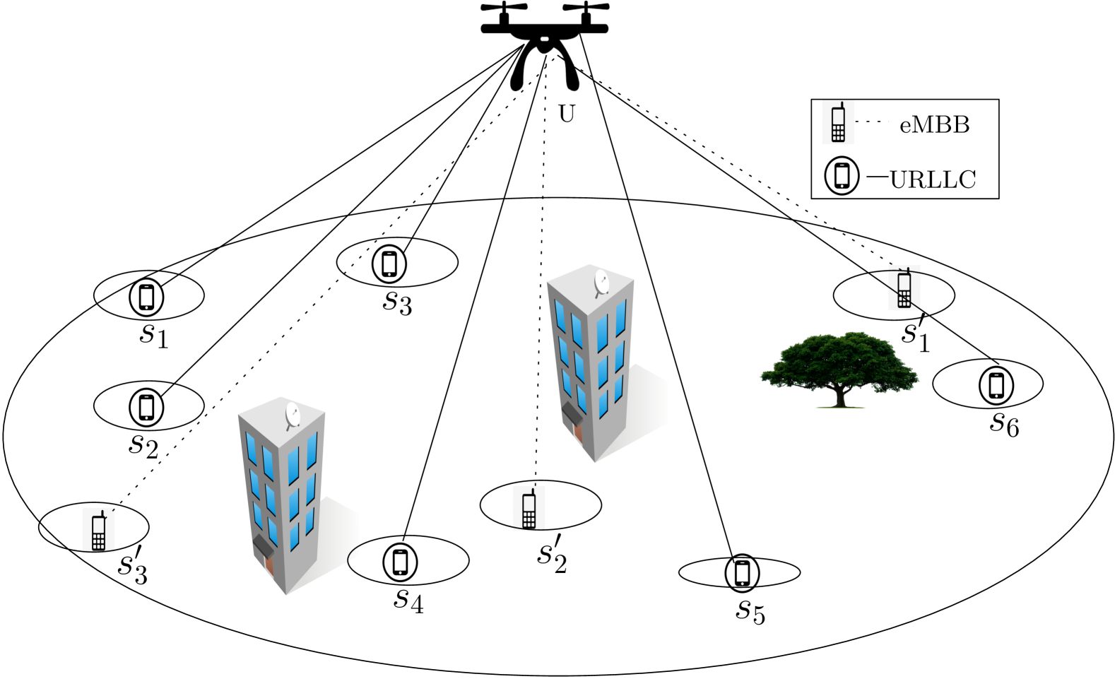
We consider an A2G cellular wireless communication system that consists of number of user equipments (UEs) , number of UAVs , and number of randomly located static obstacles. Additionally, we assume that each UE and UAV consists of a single and number of antennas, respectively, and all the UAVs are connected with a macro base station (BS) through a backhaul network. Note that UAVs are designed as multiple aerial BSs that can serve a maximum number of UEs at a time. However, in a particular time instance, each UE is connected with at most one UAV. Furthermore, we also assume that the coverage area and flying height of a UAV are and , respectively. The system model is demonstrated in Fig. 1.
II-B Channel Model
In our considered topology, UAVs, and UEs are mobile in nature. As a result, due to the presence of static obstacles, the direct LoS may be blocked by the obstacles. Therefore, the transmitted signals from UAV reach UE via the LoS and NLoS links. Due to the high path loss at mmWave frequencies, we consider only LoS links for successful communication. Let us consider that, for a particular link, depending on the GHz model, the path loss (in dB) is modeled as [16]
| (1) |
where and are environment-specific constants that characterize signal attenuation, and is Eucledian distance between and . Now, the received power at , in , is computed using the link budget equation;
| (2) |
where is the transmit power, and are the antenna gains of and respectively. Therefore, the corresponding throughput at user for UAV is [16]
| (3) |
where is channel bandwidth, is the variance of the circularly symmetric zero mean additive white Gaussian noise and is the Rician or Rayleigh random variable depending on whether it corresponds to LoS or NLoS model, respectively[17]. Note that, here, we assume orthogonal frequency division multiple access (OFDMA) where each UE communicates using orthogonal resource blocks [18].
II-C User Traffic Characterization
In our considered network topology, according to the user’s delay tolerance, we characterize the user traffic in two separate scenarios, namely eMBB and URLLC. Note that URLLC traffic is designed for very low latency and high-reliability applications, enabling real-time mission-critical communication where even a minor delay or packet loss can lead to failures or catastrophic consequences. However, eMBB traffic is designed to provide high-speed, high-capacity, and data-intensive applications. Unlike URLLC, eMBB applications can tolerate minor delays without causing critical failures. Here we focus on URLLCs and eMBB traffic that is adequate for human-type cellular and wireless communication, keeping mMTCs outside the scope of this manuscript.
II-D UAV and UE Mobility Model
For a duration of time, we assume that both UAVs and UEs can move according to any mobility model with a fixed velocity [10]. However, their positions and velocities are at the begining of . The velocity ranges of and are and , respectively. Here and are the maximum velocities of UEs and UAVs respectively, where . Since the height of UAV is assumed to be remain fixed, during time, both and will stay within the disks of radii and , respectively.

III Proposed strategy
In this section, we propose a trajectory planning algorithm for UAV based on both URLLC and eMBB traffic. Specifically, first, we propose an algorithm to identify a zone from where the highest number of URLLC users will be covered by . Next, we propose an algorithm to find the final location of within the identified zone, which serves the maximum amount of eMBB traffic. The complete process is described below.
III-A Optimal UAV position for URLLC traffic
Let be the set of all URLLC users that are being served by at a particular time instance and their corresponding positions are given by
| (4) |
where denotes the cardinality of . Additionally, we consider that is the position of at . Due to the mobile nature of the user , according to Section II-D, lies within a disk of radius during to , where is the velocity of . Here, we denote the disk within which can lie, as
| (5) |
Similarly, may lie inside a disk of radius , with at its centre, during to . That is,
| (6) |
where is the velocity of . In our considered topology, both and move in a -dimensional plane, i.e., and . We now formally define when is said to be coverable and covered by .
Definition 1.
(Coverable): An user located at is said to be coverable by located at , if the Euclidean distance between them, .
Definition 2.
(Covered): An user located at is said to be covered by located at , if
-
1.
is coverable by , and
-
2.
a LoS between and , and the achievable data rate obtained by located at from is greater than the minimum data rate threshold of .
From the core of computational geometry, if is a set of -dimensional balls, there exists with at most balls such that the minimum enclosing ball of equal to that of , i.e., , where denotes the minimum enclosing ball [19]. Note that due to the mobility of and , and randomly placed obstacles in the environment, may not be able to cover all during to . In this context, we consider only LoS links for URLLC users for reliability and data sensitivity. More precisely, we assume that the NLoS links are unable to provide the minimum data rate threshold for URLLC users. The Apollonius circle [20] of three circles is the minimum radius circle that contains all three circles and is tangent to each of them. With the help of , we find the region for that covers a maximum number of as described below.
Let us assume that , and be three coverable disks with radii , and with respect to , and , respectively. Additionally, we also consider that the center and radius of the Apollonius circle correspond to , and are and , respectively, as demonstrated in Fig. 2(a). Note that, according to the construction of , the distance between the center of and the center of disk is , where . Therefore, we get
| (7) |
Solving these three equations, we get and .
We now define a function that provides an overlapping region between two disks. Let us consider that
be two disks having centers at and with radii and , respectively. Therefore, can be computed as,
| (8) |
where, and
| (9) | |||
Let be the region with center and radius that satisfies the following conditions:
| (10) | |||
| (11) |
Additionally, to determine the position within from where and are covered, we discretize into cells/grids of unit size. Let be the set of all grid centers of that cover and . That is,
Furthermore, by repeating this procedure for every possible triplet and , we can determine the maximum number of regions in which we can deploy . Thus the potential candidate zone of is defined by
| (12) |
Consequently, to find the appropriate position from where the maximum will be covered, we construct a matrix based on the coverage status of with respect to , where is as defined below.
| (13) |
Here, is a binary matrix whose -th column sum is denoted by
| (14) |
Therefore, the column with the maximum number of one provides the location of from where the maximum number of will be covered. Let us consider that
| (15) |
be the maximum column sum corresponding to the cell . Hence, according to our proposed strategy, if we move at , the maximum number of will be covered. Note that if there exist multiple cells with highest column sum, we get a set of cells for the same. Consequently, let us consider that be the set of all the cells that satisfy the following:
| (16) |
Note that if for all triplets , and , , in a similar way as stated above, we can find by considering all possible pairs of disks and , where and . Moreover, if for all pairs and , , we do the same thing for each individual disk and finally get . Note that for the last two cases, we use a minimum enclosing ball with radius instead of using the Apollonius circles, as demonstrated in Figs. 2(b) and (c). The complete process is described in Algorithm 1.
Now in the following subsection, we will find the optimal position of , which maximizes the eMBB traffic.
III-B Optimal UAV position for both URLLC and eMBB:
Unlike URLLC traffic, eMBB traffic can withstand small delays and make the partial coverage scenario considerable. Here partial coverage means that can serve an eMBB user even if the entire disk concerning the user is not covered from . Here, we allow both LoS and NLoS communication for eMBB traffic. From the previous subsection, we have found , the region from where the maximum number of URLLC traffic is served. Here, we find the region from where the aggregate throughput obtained by eMBB users is maximum as described below.
Let be the set of all eMBB users that are being served by at and their corresponding positions are given by
| (17) |
Like URLLC users, during interval, the disk within which can lie, is given by
where is the velocity of . Let us consider that be the overlapping region between and , where is the circle of radius centered at . We discretize the region into uniform cells/grids and define as the total number of grid centers in . The throughput obtained by from is defined as
| (18) |
where is the throughput obtained by located at from located at and calculated by equation (3). Note that depends on whether is having LoS or NLoS from . Therefore, the aggregate eMBB throughput obtained from is now defined as
| (19) |
Here, we are interested in moving at for which the value of is maximum and let be such a point, i.e.,
| (20) |
Let . Note that if , we select that for which the displacement is minimum. The complete process is described in Algorithm 2.
III-C Complexity Analysis of the Algorithm
A UAV can provide services to at most UEs at a particular time slot. That is, . Let be the maximum disk radius among all the users in and be the radius of disk corresponding to UAV . Discretizing two circles of radii and into unit cells and then checking LoS status between every pair of cells, requires time complexity.
-
•
Algorithm 1: It searches for , by looping over all possible triplets, pairs and individual disks. Also, it needs to check LoS status between every pair of discretized cells to find potential zones. So, worst case time and space complexities are and respectively.
-
•
Algorithm 2: It searches for by calculating the throughput for every users in and also checking the LoS status between every pair discretized cells. Hence worst case time and space complexities are and respectively.
IV Simulation Results
In this section, our main goal is to assess how well the suggested approach works in different environmental settings. We have included a performance comparison study against an existing approach [15]. In [15], a trajectory planning is obtained by taking into account the mobility of users and the obstacles in their environment, without considering the influence of user traffic characteristics. The objective of our proposed approach is to optimize the sum throughput obtained by URLLC and eMBB users while serving a maximum number of URLLC users. The simulation parameters that we used are given in Table I
| Parameter | Value |
|---|---|
| Communication region | |
| Coverage Radius () | |
| Time slot duration () | sec |
| Transmission power | dBm [3] |
| URLLC threshold () | 10 Mbps [ITU & 3GPP] |
| Rician fading factor () | [3] |
| Altitude of UAV | [ m, m] [21] |
| Carrier frequency | GHz [16] |
| LoS link parameters | , , [16] |
| NLoS link parameters | , , [16] |
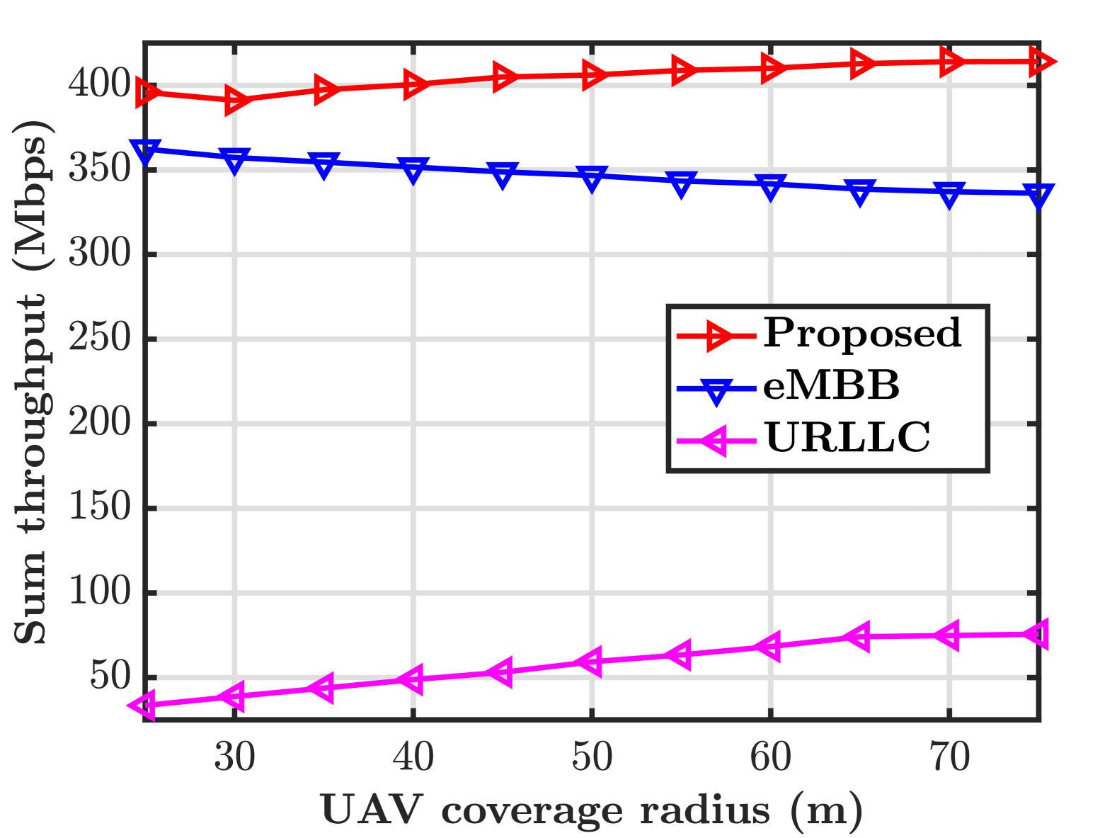
Fig.3(a) shows a comparison of eMBB throughput, URLLC throughput, and sum throughput obtained by our proposed algorithm for different UAV coverage radii. Here eMBB and URLLC throughputs represent the aggregate throughput obtained by the eMBB and URLLC users respectively. Sum throughput (Proposed) represents the sum of eMBB and URLLC throughputs. Note that the coverage radius of the UAV is increased in Fig 3(a) up to the limit such that the minimum data rate requirement of the URLLC users is satisfied. Hence the URLLC throughput increases with the increase of UAV coverage radius. On the contrary, as the UAV coverage radius increases, throughputs obtained by the eMBB users decrease as achievable throughput is inversely proportional to the distance from the user to the UAV. Since URLLC is highly prioritized, the increment of URLLC throughput is slightly more than the decrement of eMBB throughput. Hence sum throughput has an increasing trend.
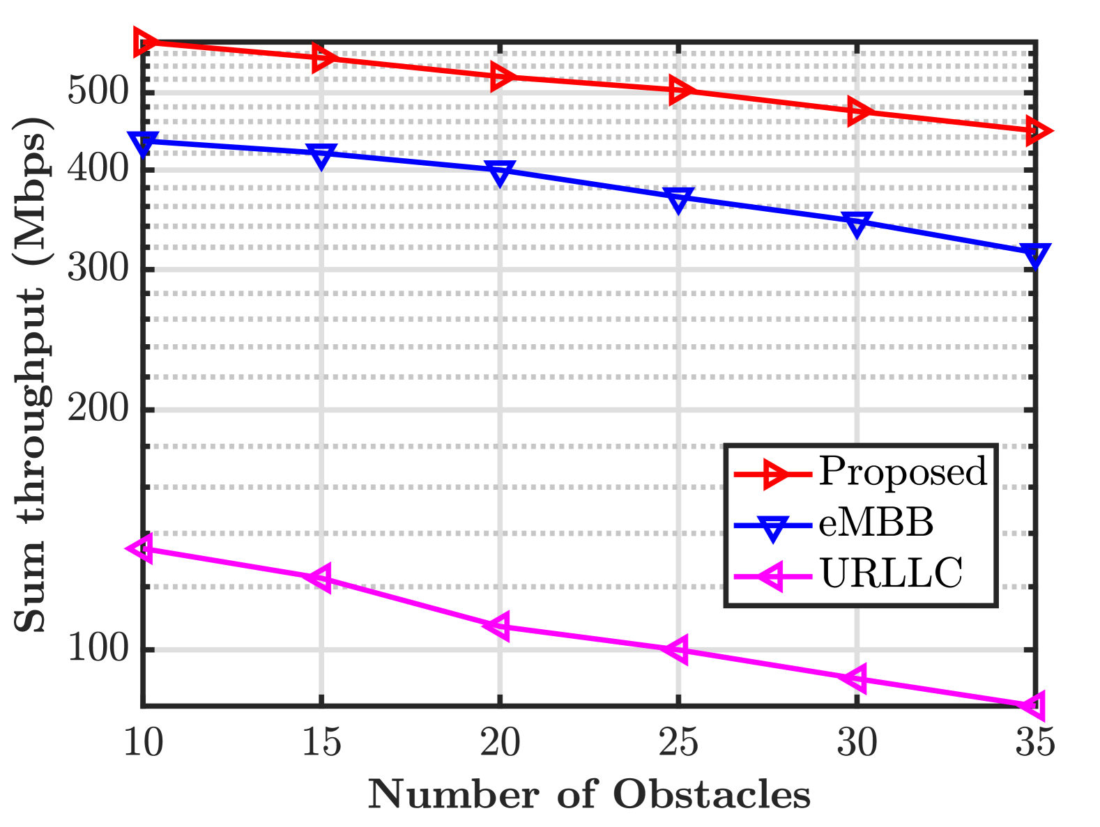
Furthermore, Fig.3(b) investigates the impact of obstacle density on the sum throughput, eMBB throughput, and URLLC throughput for a fixed number of users (). As obstacle density increases, the possibility of having LoS decreases. Thus all the throughputs decrease. Note that URLLC users are considered to be covered if all the points in its disk get LoS and eMBB users can be covered partially. That’s why we observe that URLLC throughput decreases more rapidly than the eMBB throughput. Accordingly, the sum throughput is also decreasing as a combined effect of both of them.
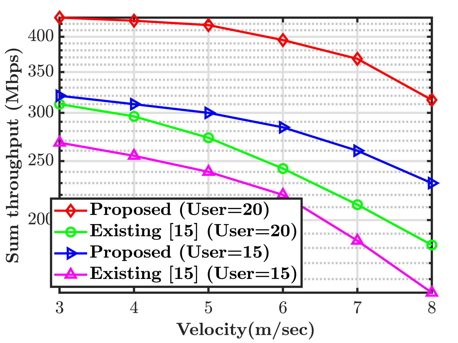
Finally, Fig.3(c) presents a comparative analysis between the proposed strategy and the existing scheme [15] under varying user velocities, for a fixed number of users ( and ). It is observed that our approach significantly outperforms the method described in [15]. The key reason behind this improvement is the differentiated treatment of URLLC and eMBB users based on their inherent service requirements, unlike [15] which treats all users uniformly. Specifically, due to the ultra-reliability and low-latency demands of URLLC, our method first prioritizes finding a zone from where serves as many URLLC users as possible. Subsequently, from that zone, we aim to find UAV positions that maximize the service for eMBB users by leveraging partial coverage, acknowledging that eMBB users can tolerate moderate latency or brief service interruptions. In contrast, the approach in [15] treats all users as URLLC, meaning that eMBB users also receive low-latency, ultra-reliable service, resulting in inefficient use of network resources. This performance gap is clearly reflected in the figure. Moreover, we observe that our strategy yields more consistent results than [15] across varying user velocities, demonstrating its robustness and adaptability to different environmental conditions.
V Conclusion
In this work, we investigated the impact of user and UAV mobility on system performance considering the varying user traffic characteristics in the air-to-ground communication framework. Based on traffic characterization and the importance of LoS links, we proposed a UAV trajectory planning algorithm. In this context, we have used the concept of Apollonius circle and minimum enclosing ball of balls to find the optimal UAV location. The numerical results demonstrated the superiority of our proposed framework over an existing benchmark scheme.
References
- [1] L. Gupta, R. Jain, and G. Vaszkun, “Survey of important issues in UAV communication networks,” IEEE Commun. Surv. Tutorial, vol. 18, no. 2, pp. 1123–1152, 2015.
- [2] X. Wang, L. Kong, F. Kong, F. Qiu, M. Xia, S. Arnon, and G. Chen, “Millimeter wave communication: A comprehensive survey,” IEEE Commun. Surv. Tutorials, vol. 20, no. 3, pp. 1616–1653, 2018.
- [3] L. Sau, P. Mukherjee, and S. C. Ghosh, “DRAMS: Double-RIS assisted multihop routing scheme for device-to-device communication,” Comput. Commun., vol. 220, pp. 52–63, Apr. 2024.
- [4] P. Popovski, K. F. Trillingsgaard, O. Simeone, and G. Durisi, “5G wireless network slicing for eMBB, URLLC, and mMTC: A communication-theoretic view,” IEEE Access, vol. 6, pp. 55 765–55 779, 2018.
- [5] C. Bockelmann, N. Pratas, H. Nikopour, K. Au, T. Svensson, C. Stefanovic, P. Popovski, and A. Dekorsy, “Massive machine-type communications in 5G: Physical and MAC-layer solutions,” IEEE Commun. Mag., vol. 54, no. 9, pp. 59–65, Oct. 2016.
- [6] M. Alzenad, A. El-Keyi, F. Lagum, and H. Yanikomeroglu, “3-D placement of an unmanned aerial vehicle base station (UAV-BS) for energy-efficient maximal coverage,” IEEE Wireless Commun. Lett., vol. 6, no. 4, pp. 434–437, Aug. 2017.
- [7] A. Al-Hourani, S. Kandeepan, and S. Lardner, “Optimal LAP altitude for maximum coverage,” IEEE Wireless Commun. Lett., vol. 3, no. 6, pp. 569–572, June 2014.
- [8] B. Galkin, J. Kibilda, and L. A. DaSilva, “Coverage analysis for low-altitude UAV networks in urban environments,” in in Proc. IEEE Global Commun. Conf. (GLOBECOM), 2017, pp. 1–6.
- [9] Y. Chen, W. Feng, and G. Zheng, “Optimum placement of UAV as relays,” IEEE Commun. Lett., vol. 22, no. 2, pp. 248–251, Feb. 2018.
- [10] C. Bettstetter, G. Resta, and P. Santi, “The node distribution of the random waypoint mobility model for wireless ad hoc networks,” IEEE Trans. Mob. Comput., vol. 2, no. 3, pp. 257–269, July-Sept. 2003.
- [11] L. Liu, S. Zhang, and R. Zhang, “CoMP in the sky: UAV placement and movement optimization for multi-user communications,” IEEE Trans. Commun., vol. 67, no. 8, pp. 5645–5658, Aug. 2019.
- [12] H. Yan, Y. Chen, and S.-H. Yang, “UAV-enabled wireless power transfer with base station charging and UAV power consumption,” IEEE Trans. Veh. Technol., vol. 69, no. 11, pp. 12 883–12 896, Nov. 2020.
- [13] Y. Zeng and R. Zhang, “Energy-efficient UAV communication with trajectory optimization,” IEEE Trans. Wireless Commun., vol. 16, no. 6, pp. 3747–3760, June 2017.
- [14] H. Ren, C. Pan, K. Wang, W. Xu, M. Elkashlan, and A. Nallanathan, “Joint transmit power and placement optimization for URLLC-enabled UAV relay systems,” IEEE Trans. Veh. Technol., vol. 69, no. 7, pp. 8003–8007, July 2020.
- [15] G. Li, C. Zhuang, Q. Wang, Y. Li, X. Xu, and W. Zhou, “A uav real-time trajectory optimized strategy for moving users,” in Proc. 11th Int. Conf. Wireless Commun. Signal Process. (WCSP). IEEE, 2019, pp. 1–6.
- [16] M. R. Akdeniz, Y. Liu, M. K. Samimi, S. Sun, S. Rangan, T. S. Rappaport, and E. Erkip, “Millimeter wave channel modeling and cellular capacity evaluation,” IEEE J. Sel. Areas Commun., vol. 32, no. 6, pp. 1164–1179, June. 2014.
- [17] L. Sau, P. Mukherjee, and S. C. Ghosh, “Priority-aware grouping-based multihop routing scheme for RIS-assisted wireless networks,” IEEE Trans. Network Sci. Eng., vol. 12, no. 2, pp. 1172–1185, Mar.-Apr. 2025.
- [18] T. Weiss, J. Hillenbrand, A. Krohn, and F. Jondral, “Mutual interference in OFDM-based spectrum pooling systems,” in 2004 IEEE 59th Veh. Technol. Conf., vol. 4, 2004, pp. 1873–1877.
- [19] K. Fischer and B. Gartner, “The smallest enclosing ball of balls: combinatorial structure and algorithms,” in in Proc. 19th Annu. Symp. on Comput. Geom., 2003, pp. 292–301.
- [20] H. Coxeter, “The problem of Apollonius,” Amer. Math. Monthly, vol. 75, no. 1, pp. 5–15, 1968.
- [21] F. Li, C. He, X. Li, J. Peng, and K. Yang, “Geometric analysis-based 3D anti-block UAV deployment for mmWave communications,” IEEE Commun. Lett., vol. 26, no. 11, pp. 2799–2803, Nov. 2022.