Coherent manipulation of interacting electron qubits on solid neon
Solid neon has emerged as a pristine material host for electron qubits. Single electron-on-solid-neon (eNe) charge qubits have shown extraordinarily long coherence times and high operation fidelities. Realizing two-qubit gates in this platform is the next major step for realistic quantum information processing. In this work, we demonstrate frequency- and time-domain coherent manipulation of multiple eNe charge qubits that are coupled by short-range charge interactions. Cross-resonance and bSWAP two-qubit gates are implemented, laying the foundation for universal quantum computing. An inter-qubit coupling strength exceeding 60 MHz has been observed, promising fast gate speed and suppressed infidelity. These results highlight the potential to scale up the eNe qubit platform toward universal quantum computing.
Electrons on solid neon (eNe) is an emerging solid-state qubit platform [1, 2, 3, 4]. Qubits based on charge states of eNe have shown great coherence performance and high-fidelity single-qubit operation because of the robust electron host environment offered by the neon layer [2]. Meanwhile, the directness of charge qubits in terms of control and detection via electrical fields can largely simplify circuit design in a system with high qubit volume. To scale up charge qubits on solid neon, it is essential to demonstrate coherent interactions between them [5, 4]. In semiconductor electron hosts, strong coupling between qubits was initially established through short-range interactions [6, 7, 8], which showcased the advantage of electron qubits in large-number integration on a small chip [9, 10]. For electrons on cryogenic substrates, short-range interactions have also been proposed to perform two-qubit gates and establish entanglements [4, 11, 12].
Both theoretical and experimental results indicate the crucial role of the roughness of the neon surface in defining the properties of single qubits [13, 14, 15], which could form during the current neon solidification process through its liquid phase. The surface profile could further provide the possibility for the local formation of multi-electron traps. Previously, we have observed the case of multiple electron qubits loaded onto a single niobium superconducting resonator [2]. Even though they simultaneously achieved strong coupling with the cavity, the inter-qubit coupling strength is small, preventing the demonstration of two-qubit operations. When two qubits are located close to each other, short-range interaction strength could increase, surpassing the qubits’ decoherence and enabling coherent two-qubit operation. Therefore, it is straightforward to pursue coherent local coupling between qubits on solid neon to demonstrate its scalability, which may also offer a unique testbed for studying the entanglement of electrons in free space and for the simulation of many-body quantum systems [16, 17].
In this work, we achieve the coherent manipulation of multiple interacting electron qubits on solid neon in the circuit quantum electrodynamics architecture (cQED) [18, 19]. Qubit spectroscopy measurements show strong coupling between two qubits on solid neon with an inter-qubit coupling strength of 3.35 MHz. Further, by driving one of the two qubits, which is strongly coupled with the superconducting resonator, we are able to demonstrate cross-resonance (CR) and bSWAP types of all-microwave two-qubit operations [20]. The experiment results match well with theoretical simulations of the two-qubit coupled system based on characterized parameters. Moreover, we observe even stronger coupling within a three-qubit system, with a maximum coupling strength up to = 62.5 MHz. These results reveal the short-range coherent interactions between qubits on solid neon, paving the way for further scaling up the system for applications in quantum computing and simulation.
Multi-qubit systems
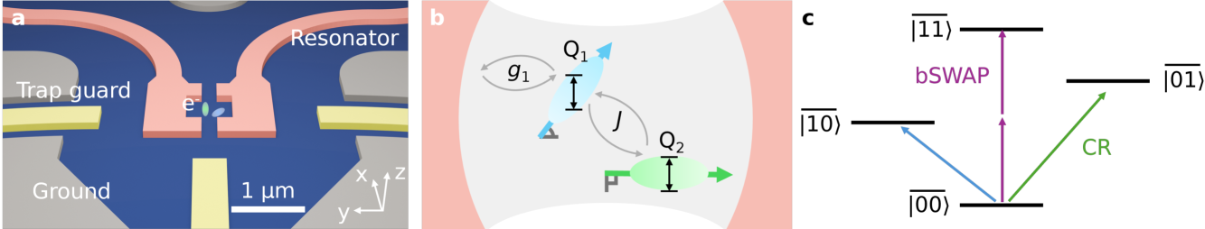
We utilize the cQED architecture to drive and read out charge qubits on solid neon coupled with microwave photons within a superconducting resonator. Specifically, multiple qubits could exist on the neon film near the designed electron trapping area, as shown in Fig. 1a, whose coupling strength with the resonator is determined by the alignment between the qubits’ dipole moments and the local microwave electrical field. For two closely arranged qubits and , they can directly couple with each other through short-range charge interactions. The qubit-resonator system’s Hamiltonian can be written as (refs. [21, 22, 23])
| (1) |
where , , and are the resonator, qubits, and interaction Hamiltonians. is the resonator frequency, is the transition frequency of , is the coupling strength between the resonator and , is the inter-qubit coupling strength between and . and are the annihilation and creation operators of resonator photons. , , and are the Pauli-, lowering, and raising operators acting on . The system is driven by microwaves with a time-dependent amplitude and frequency , and the driving Hamiltonian can be written as
| (2) |
where is the ratio for direct driving on (ref. [22]). Because of the disordered neon surface, two closely arranged qubits may have distinct coupling strengths with the superconducting resonator, depending on their dipole orientation [24, 18]. As shown in Fig. 1b, inside a two-qubit coupled system, with a dipole moment orthogonal to the MW field within a superconducting cavity could result in a close to zero qubit-cavity coupling strength. In such a case, if is still coupled with the resonator via a finite dipole alignment, and is interacting with at a strength , we will have a system Hamiltonian with , and (ref. [22]).
Such a two-qubit system could support all-microwave-driven two-qubit operations including the cross-resonance (CR) and bSWAP types of two-qubit gates, as shown in Fig. 1c. For CR gates, could be excited by driving at the frequency of , generating the transition (refs. [21, 25]). For bSWAP gates, and could be driven monochromatically through a two-photon process near the frequency middle point between them, generating the transition (refs. [22, 26]). All-microwave two-qubit gates are widely applied to fixed-frequency qubits thanks to their easy implementation, which also preserves the qubits’ coherence by avoiding fast electrostatic and flux gating [20, 25, 22, 27, 28].
Two-qubit strong coupling
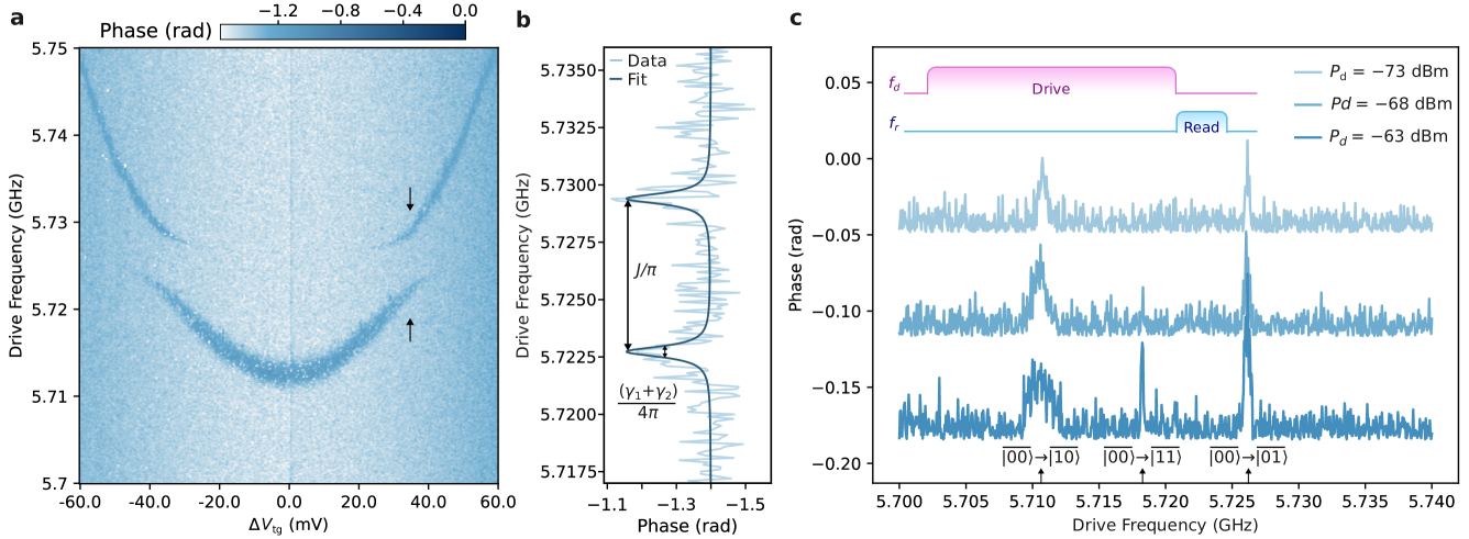
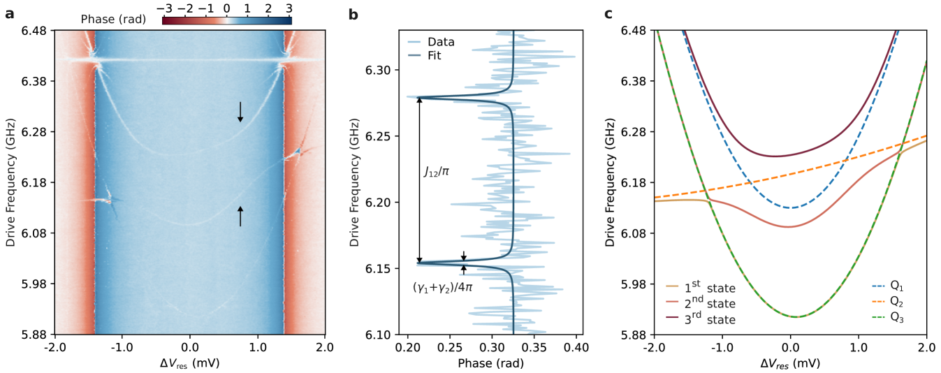
We have achieved a strong coupling between two qubits on solid neon. Figure 2a plots the two-tone measured qubit spectroscopy, in which we probe the system at the resonator frequency with low power, approximately -130 dBm reaching the resonator’s input coupler, while sending a second continuous-wave tone with scanning frequency. Two clear avoided crossings are observed while tuning the bias voltage on the trap guard electrode (), with a splitting magnitude of 3.35 MHz, larger than the linewidth of the hybrid states above and below the splitting, as shown in Fig. 2b. This indicates the strong coupling between a qubit (), which is visible in the two-tone spectroscopy, and another invisible one (). has a hyperbolic frequency dependency on , with a charge sweet-spot (SS) located near 5.71 GHz, which is about 40 MHz above the resonator frequency at 5.668 GHz. The coupling between and the resonator dispersively pushes the resonator spectrum, especially when is tuned to its sweet-spot frequency, as shown in the Supplementary Information. Based on this, we estimate the coupling strength between and the resonator to be MHz. In contrast, the interaction strength between and the superconducting resonator is much weaker than that for , resulting in negligible -state-dependent resonator frequency shift and the invisible spectroscopy of in Fig. 2a. In addition, the spectroscopic relations of the two splittings indicate that the frequency of is much less sensitive to compared to that for , with a nearly constant frequency of 5.7261 GHz in the voltage scanning range of Fig. 2a.
We attribute the two-qubit coupling to short-range interactions. The spectroscopic observations reveal a quantum system with two coherently coupled qubits on solid neon, while only one of them is strongly coupled to the superconducting resonator, corresponding to the system with 0 and 0. Due to the distinct coupling strengths between the two qubits and the resonator, we can rule out the case that the two qubits achieved strong coupling via virtual microwave photon exchange through the resonator, in which the inter-qubit exchange strength , where are the detune between the qubits and the resonator [29].
Despite the fact that only has a strong interaction with the superconducting resonator, we have managed to probe utilizing the inter-qubit coupling. When biased at ’s SS, instead of probing with continuous waves of weak power as in the case of Fig. 2a, we can first apply a long square pulse (10 µs) with varying frequency followed by a short square probe pulse (700 ns) of high power ( -100 dBm reaching the resonator) at the resonator frequency, shown as the inset pulse sequence in Fig. 2c. These parameters were chosen to balance the lifetime of and the readout signal-to-noise ratio. The long driving pulse saturates the two-qubit system to a certain state. Following that, the high-power readout pulse will populate the resonator with averge intra-cavity photon number and induce a blue ac-Stark shift of at , due to the dispersive coupling between it and the resonator [19, 2]. Thanks to the undetectable coupling between and the resonator, the probe signal will not affect directly. Given the dispersive coupling strength of MHz, ’s frequency can shift across ’s frequency as builds up and drops down, occurring at approximately 20. Therefore, the pulsed probe will act as a SWAP operation between and (ref. [29]), which eventually results in a -state-dependent readout at the resonator frequency. This effect is turned-off when the probe tone is weak, as in Fig. 2a. See Supplementary Information for an example simulation of the SWAP due to the intra-cavity photon population.
As shown in Fig. 2c, with this method, we perform pulsed qubit spectroscopy when V. At low driving power, we observe two transitions at 5.711 GHz and 5.726 GHz, corresponding to frequencies of at its SS and . The appearance of transition indicates that the long driving pulse excited to a certain population, corresponding to the CR transition of a two-qubit coupled system [25, 21], as shown in Fig. 1c. With an increase in the driving power, we observe another transition peak () near the middle of the and frequencies at 5.718 GHz. This corresponds to the bSWAP type of two-qubit operation in Fig. 1c (refs. [22, 26]). In summary, through spectroscopic characterization, we have observed the coherent coupling between two qubits on solid neon, which can support both the CR and the bSWAP types of two-qubit operation.
Two-qubit gate operation
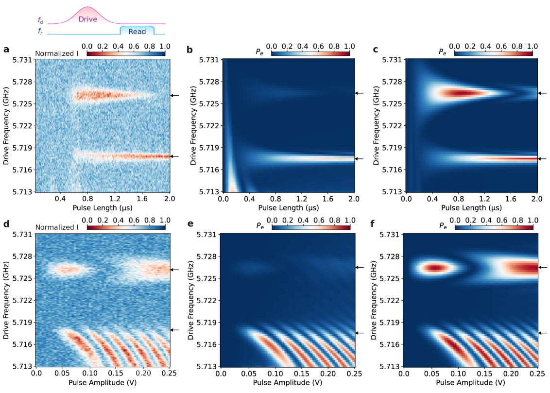
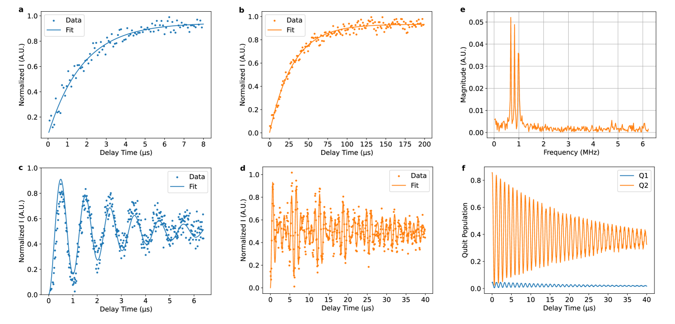
Following spectroscopic characterization of the coupled system, we perform pulse-driving two-qubit operations corresponding to the CR and bSWAP gates. Figure 3a plots the readout signal following Gaussian-shaped driving pulses with varying lengths and -70 dBm reaching the resonator input coupler. The pulses are truncated at on each side, where is the standard deviation of the Gaussian envelope. The parameters of the readout pulses are the same as described in the last section. Two oscillation features corresponding to the CR operation near 5.726 GHz and the bSWAP operation near 5.718 GHz can be observed. Based on the system Hamiltonian, we numerically simulate qubit excited state population during the pulse-driving process [30]. See Supplementary Information for simulation details. Fig. 3b and 3c plot the simulated excited state population evolution of and , matching the features of the two-qubit operations observed in experiments. The black solid lines in Fig. 4a and 4b plot the line cuts at these two oscillations, respectively. The blue and orange curves plot the simulated and excited state population after applying the driving pulse, matching the measured oscillation feature. For the CR operation, was drived by driving at the transition frequency of , whose excited state population reached maximum when the pulse length was approximately 0.8 µs, as reflected in the readout in-phase signal (I). On the other hand, was barely excited.
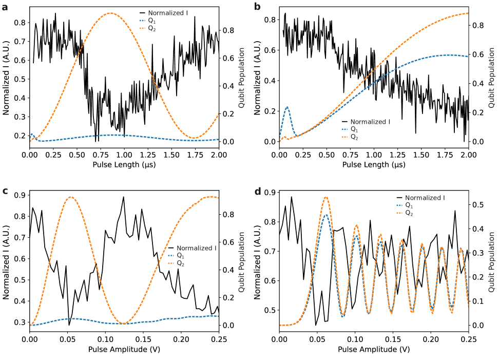
For the bSWAP operation, the two-photon process drives the two qubits simultaneously, while the oscillation frequency is much lower than the CR operation. Under a square driving pulse with amplitude , and negligible direct driving on the , the oscillation frequency induced by CR operation is (ref. [21]). In bSWAP operation, the oscillation frequency is approximately (ref. [22]), where is the frequency separation between and . When the bSWAP operation performs a rotation, which is about 2 µs in our case, it is locally equivalent to an iSWAP gate with appropriate single-qubit rotations [22].
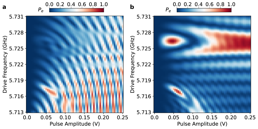
In addition, we perform pulse amplitude-dependent Rabi oscillation measurement with a Gaussian-shaped driving pulse of 800 ns length and output pulse amplitude varying from 0.0 V to 0.25 V, corresponding to zero power to -57 dBm reaching the resonator input coupler. Again, we observe oscillating patterns near 5.726 GHz and 5.718 GHz, corresponding to the CR and bSWAP operations. We attribute the “waterfall-like” patterns in the frequency range between 5.713 - 5.718 GHz in Fig. 3d to the effects of the Gaussian pulse shape and the ac-Stark shift of under higher driving power, which are reproduced by simulations in Fig. 3e and 3f. See detailed discussion in the Supplementary Information. In Fig. 4c and 4d, the line cuts at those two driving frequencies matched well with the numerically simulated qubit population evolution.
These results demonstrate, for the first time, two-qubit operations in a solid neon platform, revealing the potential for scaling up quantum systems based on charge qubits on solid neon. Further optimization of the two-qubit gate and readout is crucial to achieving high-fidelity operations.
Three-qubit strong coupling
To further demonstrate the scalability via short-range interactions, we have managed to create a system with three qubits on solid neon. Figure 5a plots the two-tone measured qubit spectrum while varying the gate voltage on the resonator electrode (), revealing the energy diagram of this three-qubit system. One of them () is directly coupled with a superconducting resonator, while the other two ( and ) are serially coupled to . Compared to , the interactions strengths of and with the resonator are weak. We do not observe the avoided crossing between them and the resonator, and the dispersive phase shift of the resonator induced by and is also small when they are not hybridized with .
In Fig. 5b, the line cut around 0.74 mV shows a coupling strength of MHz between and . On the other hand, the coupling strength between and is much smaller, at approximately 5 MHz level. Due to the weak interaction between and the resonator, we attribute the three-qubit coupling to short-range interactions instead of virtual photon exchange via the resonator.
Figure 5c plots the calculated eigenstates of the system, which match well with the two-tone spectroscopy. and have closely arranged SS near 6.13 GHz, while ’s SS is more detuned to approximately 5.91 GHz. All three qubits are responsive to the bias voltage on the resonator electrode with various sensitivity. See details in the Supplementary Information for those parameters applied in the calculation. Due to the strong coupling strength between and , the state mixing of the three qubits results in the energy diagram of the coupled system, which deviates from the undressed qubit spectrum. As a result, the three mixed states are all visible in the two-tone measurement in Fig. 5a. These observations indicate the possibilities of creating multi-qubit coupled systems on solid neon that can be applied for small- to middle-scale quantum simulations [17, 16].
Discussion and outlook
In this work, we have realized coherently interacting multiple qubits on solid neon, mediated by short-range interactions. In a two-qubit system, both spectroscopic avoided crossing and time-domain pulse operation have demonstrated coherent qubit interactions. Cross-resonance and bSWAP two-qubit operation have been demonstrated, paving the way for the optimization of high-fidelity two-qubit gates on solid neon. Further, a three-qubit system with over 60 MHz inter-qubit coupling strength shows the potential of building more complex system with qubits on solid neon. In both of the two systems studied in this work, qubits can acquire distinct coupling strength with superconducting resonators. This offers the possibility to utilize qubits with dipole moment normal to the resonator microwave mode as quantum memories for other couples coupled to them [31, 32], or as intermediate quantum buses [33]. These observations also reveal the complexity of the charge environment on solid neon films and the potential effects of the neon surface profile in determining the qubit properties, including the interaction strength with resonators [14, 15].
Establishing coherent interactions between qubits on solid neon is crucial for scaling up this emergent solid-state qubit platform. However, a multi-qubit system purely relying on short-range interactions will pose challenges to integrating control and real-out circuits. Entanglement between distant qubits through superconducting cavity buses could ease the limits on the local interaction [29, 34, 35, 36]. High-impedance resonators made of high-kinetic inductance thin films [37, 38] and Josephson junction arrays [39, 40] have been applied to achieve coherent interactions between distant semiconductor qubits. Further improvements in the control of individual qubit properties above solid neon and the development of a compatible frequency-tunable and high-impedance resonator would facilitate remote entanglement between distant qubits and hybridize it with other quantum platforms [32, 41]. An on-chip quantum network will then be possible through the integration of short-range and long-range coupling with qubits on solid neon.
Methods
Devices and experiments
The data presented in Fig. 1 and 2 were collected on a high-impedance titanium nitride (TiN) splitting superconducting resonator, the same as the one in ref. [14]. The resonator supports a differential mode at 5.668 GHz with a total linewidth of 0.38 MHz. Electrodes with on-chip low-pass filters are connected to the resonator pins and trap guards surrounding the electron-trapping area to apply bias voltages for tuning qubits transition frequency. The device was mounted on a home-made printed circuit board (PCB), sealed in a copper cell with neon filling lines, tungsten filament, and electrical connectors on top of the cell lid. The cryogenic and room temperature electronics setups are the same as those in ref. [14]. The data presented in Fig. 3 were collected on a niobium splitting superconducting resonator, the same as the one in ref. [1, 2]. The resonator supports a differential mode at 6.426 GHz, with a total linewidth of MHz. The sample mounting, cryogenic and room temperature electronic setups were the same as those in refs. [1, 2].
The neon growth procedure is the same as that described in ref. [14]. In summary, the dilution fridge is warmed up to create a temperature gradient from 27 K to 25 K between its 4K plate and mixing chamber (MXC) plate. At that moment, neon gas is supplied from a room-temperature gas handling system in the form of puffs and filled onto the device chip in the form of liquid. After a desired amount of neon filling, the fridge heater is turned off to let the fridge cool down to base temperature.
Electrons are deposited on to the chip by sending pulsed current on to the tungsten filaments mounted above the device chip. During the electron firing process, temperature sensed on the MXC plate can increase up to 100 mK. The details of the procedure and discussion of the electron deposition process can be found in ref. [14]
Simulation of mutli-qubit coupled system
The populations of qubits in coupled systems are simulated based on their Hamiltonian, using the QuTiP package [30]. For the numerical data presented in Fig. 3, we use Eq. 1 and 2 as the Hamiltonian, with parameters listed in the Supplementary Information. The Lindblad master equation is applied to model the effects of relaxation and dephasing:
| (3) |
where . is the system density matrix. is the relaxation lifetime of , and is the pure dephasing lifetime of , which are adopted from relaxation and Ramsey measurements as shown in the Supplementary Information.
Data availability
The data that support the findings of this study are available from the corresponding authors upon request. Source data are provided with this paper.
Code availability
The codes used to perform the experiments and to analyze the data in this work are available from the corresponding authors upon request.
Acknowledgements.
D. J. and X. L. acknowledge support from the Air Force Office of Scientific Research (AFOSR) under Award No. FA9550-23-1-0636. D. J., X. Z., and Y. H. acknowledge support from the Julian Schwinger Foundation for Physics Research. D. J. acknowledges support from the Department of Energy (DOE) under Award No. DE-SC0025542 and the National Science Foundation (NSF) under Award No. OSI-2426768. Work performed at the Center for Nanoscale Materials, a U.S. Department of Energy Office of Science User Facility, was supported by the U.S. DOE, Office of Basic Energy Sciences, under Contract No. DEAC02-06CH11357.References
- Zhou et al. [2022] X. Zhou, G. Koolstra, X. Zhang, G. Yang, X. Han, B. Dizdar, X. Li, R. Divan, W. Guo, K. W. Murch, et al., “Single electrons on solid neon as a solid-state qubit platform,” Nature 605, 46–50 (2022).
- Zhou et al. [2024] X. Zhou, X. Li, Q. Chen, G. Koolstra, G. Yang, B. Dizdar, Y. Huang, C. S. Wang, X. Han, X. Zhang, et al., “Electron charge qubit with 0.1 millisecond coherence time,” Nature Physics 20, 116–122 (2024).
- Guo, Konstantinov, and Jin [2024] W. Guo, D. Konstantinov, and D. Jin, “Quantum electronics on quantum liquids and solids,” Progress in Quantum Electronics 99, 100552 (2024).
- Jennings et al. [2024] A. Jennings, X. Zhou, I. Grytsenko, and E. Kawakami, “Quantum computing using floating electrons on cryogenic substrates: Potential and challenges,” Applied Physics Letters 124, 120501 (2024).
- Platzman and Dykman [1999] P. Platzman and M. Dykman, “Quantum computing with electrons floating on liquid helium,” Science 284, 1967–1969 (1999).
- Burkard et al. [2023] G. Burkard, T. D. Ladd, A. Pan, J. M. Nichol, and J. R. Petta, “Semiconductor spin qubits,” Reviews of Modern Physics 95, 025003 (2023).
- Petta et al. [2005] J. R. Petta, A. C. Johnson, J. M. Taylor, E. A. Laird, A. Yacoby, M. D. Lukin, C. M. Marcus, M. P. Hanson, and A. C. Gossard, “Coherent manipulation of coupled electron spins in semiconductor quantum dots,” Science 309, 2180–2184 (2005).
- Borsoi et al. [2024] F. Borsoi, N. W. Hendrickx, V. John, M. Meyer, S. Motz, F. Van Riggelen, A. Sammak, S. L. De Snoo, G. Scappucci, and M. Veldhorst, “Shared control of a 16 semiconductor quantum dot crossbar array,” Nature Nanotechnology 19, 21–27 (2024).
- Vandersypen et al. [2017] L. Vandersypen, H. Bluhm, J. Clarke, A. Dzurak, R. Ishihara, A. Morello, D. Reilly, L. Schreiber, and M. Veldhorst, “Interfacing spin qubits in quantum dots and donors—hot, dense, and coherent,” npj Quantum Information 3, 34 (2017).
- Zwerver et al. [2022] A. Zwerver, T. Krähenmann, T. Watson, L. Lampert, H. C. George, R. Pillarisetty, S. Bojarski, P. Amin, S. Amitonov, J. Boter, et al., “Qubits made by advanced semiconductor manufacturing,” Nature Electronics 5, 184–190 (2022).
- Beysengulov et al. [2024] N. R. Beysengulov, Ø. S. Schøyen, S. D. Bilek, J. B. Flaten, O. Leinonen, M. Hjorth-Jensen, J. Pollanen, H. E. Kristiansen, Z. J. Stewart, J. D. Weidman, et al., “Coulomb interaction-driven entanglement of electrons on helium,” PRX Quantum 5, 030324 (2024).
- Kawakami et al. [2023] E. Kawakami, J. Chen, M. Benito, and D. Konstantinov, “Blueprint for quantum computing using electrons on helium,” Physical Review Applied 20, 054022 (2023).
- Kanai, Jin, and Guo [2024] T. Kanai, D. Jin, and W. Guo, “Single-electron qubits based on quantum ring states on solid neon surface,” Physical Review Letters 132, 250603 (2024).
- Li et al. [2025] X. Li, C. S. Wang, B. Dizdar, Y. Huang, Y. Wen, W. Guo, X. Zhang, X. Han, X. Zhou, and D. Jin, “Noise-resilient solid host for electron qubits above 100 mk,” arXiv:2502.01005v2 (2025).
- Zheng, Song, and Murch [2025] K. Zheng, X. Song, and K. W. Murch, “Surface morphology assisted trapping of strongly coupled electron-on-neon charge states,” arXiv preprint arXiv:2503.01847 (2025).
- Hensgens et al. [2017] T. Hensgens, T. Fujita, L. Janssen, X. Li, C. Van Diepen, C. Reichl, W. Wegscheider, S. Das Sarma, and L. M. Vandersypen, “Quantum simulation of a fermi–hubbard model using a semiconductor quantum dot array,” Nature 548, 70–73 (2017).
- Wang et al. [2023] Y. Wang, Y. Chen, H. T. Bui, C. Wolf, M. Haze, C. Mier, J. Kim, D.-J. Choi, C. P. Lutz, Y. Bae, et al., “An atomic-scale multi-qubit platform,” Science 382, 87–92 (2023).
- Schuster et al. [2010] D. Schuster, A. Fragner, M. Dykman, S. Lyon, and R. Schoelkopf, “Proposal for manipulating and detecting spin and orbital states of trapped electrons on helium using cavity quantum electrodynamics,” Physical Review Letters 105, 040503 (2010).
- Blais et al. [2021] A. Blais, A. L. Grimsmo, S. M. Girvin, and A. Wallraff, “Circuit quantum electrodynamics,” Reviews of Modern Physics 93, 025005 (2021).
- Krantz et al. [2019] P. Krantz, M. Kjaergaard, F. Yan, T. P. Orlando, S. Gustavsson, and W. D. Oliver, “A quantum engineer’s guide to superconducting qubits,” Applied Physics Reviews 6, 021318 (2019).
- Rigetti and Devoret [2010] C. Rigetti and M. Devoret, “Fully microwave-tunable universal gates in superconducting qubits with linear couplings and fixed transition frequencies,” Physical Review B 81, 134507 (2010).
- Poletto et al. [2012] S. Poletto, J. M. Gambetta, S. T. Merkel, J. A. Smolin, J. M. Chow, A. Córcoles, G. A. Keefe, M. B. Rothwell, J. Rozen, D. W. Abraham, et al., “Entanglement of two superconducting qubits in a waveguide cavity via monochromatic two-photon excitation,” Physical Review Letters 109, 240505 (2012).
- Magesan and Gambetta [2020] E. Magesan and J. M. Gambetta, “Effective hamiltonian models of the cross-resonance gate,” Physical Review A 101, 052308 (2020).
- Koolstra, Yang, and Schuster [2019] G. Koolstra, G. Yang, and D. I. Schuster, “Coupling a single electron on superfluid helium to a superconducting resonator,” Nature communications 10, 5323 (2019).
- Chow et al. [2011] J. M. Chow, A. D. Córcoles, J. M. Gambetta, C. Rigetti, B. R. Johnson, J. A. Smolin, J. R. Rozen, G. A. Keefe, M. B. Rothwell, M. B. Ketchen, et al., “Simple all-microwave entangling gate for fixed-frequency superconducting qubits,” Physical Review Letters 107, 080502 (2011).
- Roth et al. [2017] M. Roth, M. Ganzhorn, N. Moll, S. Filipp, G. Salis, and S. Schmidt, “Analysis of a parametrically driven exchange-type gate and a two-photon excitation gate between superconducting qubits,” Physical Review A 96, 062323 (2017).
- Chow et al. [2012] J. M. Chow, J. M. Gambetta, A. D. Corcoles, S. T. Merkel, J. A. Smolin, C. Rigetti, S. Poletto, G. A. Keefe, M. B. Rothwell, J. R. Rozen, et al., “Universal quantum gate set approaching fault-tolerant thresholds with superconducting qubits,” Physical Review Letters 109, 060501 (2012).
- Córcoles et al. [2013] A. D. Córcoles, J. M. Gambetta, J. M. Chow, J. A. Smolin, M. Ware, J. Strand, B. L. Plourde, and M. Steffen, “Process verification of two-qubit quantum gates by randomized benchmarking,” Physical Review A 87, 030301 (2013).
- Majer et al. [2007] J. Majer, J. Chow, J. Gambetta, J. Koch, B. Johnson, J. Schreier, L. Frunzio, D. Schuster, A. A. Houck, A. Wallraff, et al., “Coupling superconducting qubits via a cavity bus,” Nature 449, 443–447 (2007).
- Johansson, Nation, and Nori [2012] J. R. Johansson, P. D. Nation, and F. Nori, “Qutip: An open-source python framework for the dynamics of open quantum systems,” Computer Physics Communications 183, 1760–1772 (2012).
- Wendin [2017] G. Wendin, “Quantum information processing with superconducting circuits: a review,” Reports on Progress in Physics 80, 106001 (2017).
- Xie et al. [2024] J.-k. Xie, R.-t. Cao, Y.-l. Ren, S.-l. Ma, R. Zhang, and F.-l. Li, “High-fidelity quantum memory with floating electrons coupled to superconducting circuits,” Physical Review A 110, 052607 (2024).
- Baart et al. [2017] T. A. Baart, T. Fujita, C. Reichl, W. Wegscheider, and L. M. K. Vandersypen, “Coherent spin-exchange via a quantum mediator,” Nature Nanotechnology 12, 26–30 (2017).
- Dijkema et al. [2025] J. Dijkema, X. Xue, P. Harvey-Collard, M. Rimbach-Russ, S. L. de Snoo, G. Zheng, A. Sammak, G. Scappucci, and L. M. Vandersypen, “Cavity-mediated iswap oscillations between distant spins,” Nature Physics 21, 168–174 (2025).
- Cheung et al. [2024] L. Cheung, R. Haller, A. Kononov, C. Ciaccia, J. Ungerer, T. Kanne, J. Nygård, P. Winkel, T. Reisinger, I. Pop, et al., “Photon-mediated long-range coupling of two andreev pair qubits,” Nature Physics 20, 1793–1797 (2024).
- Bøttcher et al. [2022] C. Bøttcher, S. Harvey, S. Fallahi, G. Gardner, M. Manfra, U. Vool, S. Bartlett, and A. Yacoby, “Parametric longitudinal coupling between a high-impedance superconducting resonator and a semiconductor quantum dot singlet-triplet spin qubit,” Nature Communications 13, 4773 (2022).
- Harvey-Collard et al. [2020] P. Harvey-Collard, G. Zheng, J. Dijkema, N. Samkharadze, A. Sammak, G. Scappucci, and L. M. Vandersypen, “On-chip microwave filters for high-impedance resonators with gate-defined quantum dots,” Physical Review Applied 14, 034025 (2020).
- Harvey-Collard et al. [2022] P. Harvey-Collard, J. Dijkema, G. Zheng, A. Sammak, G. Scappucci, and L. M. Vandersypen, “Coherent spin-spin coupling mediated by virtual microwave photons,” Physical Review X 12, 021026 (2022).
- Stockklauser et al. [2017] A. Stockklauser, P. Scarlino, J. V. Koski, S. Gasparinetti, C. K. Andersen, C. Reichl, W. Wegscheider, T. Ihn, K. Ensslin, and A. Wallraff, “Strong coupling cavity qed with gate-defined double quantum dots enabled by a high impedance resonator,” Physical Review X 7, 011030 (2017).
- Landig et al. [2019] A. J. Landig, J. V. Koski, P. Scarlino, C. Müller, J. C. Abadillo-Uriel, B. Kratochwil, C. Reichl, W. Wegscheider, S. N. Coppersmith, M. Friesen, et al., “Virtual-photon-mediated spin-qubit–transmon coupling,” Nature communications 10, 5037 (2019).
- Pan and Li [2025] X.-F. Pan and P.-B. Li, “Nonlinear tripartite coupling of single electrons on solid neon with magnons in a hybrid quantum system,” arXiv preprint arXiv:2503.08587 (2025).
Coherent manipulation of interacting electron qubits on solid neon
S1 Resonator dispersive shift
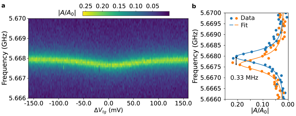
of the two-qubit coupled system presented in the main text is coupled to the resonator with its charge sweet-spot (SS) above the resonator frequency. Due to the interaction, the resonator is dispersively shifted when is biased close to its SS, as shown in Fig. S1a. The line-cut of the resonator spectrum when ground-state is on its SS shows MHz red shift compared to the bare resonator frequency, as shown in Fig. S1b. We estimated the coupling strength between and resonator to be MHz based on this resonator dispersive shift and (ref. [19]), where MHz.
S2 Pulsed readout of
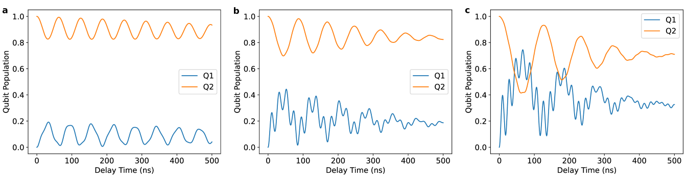
We demonstrate the pulsed readout process of with the following simulation. Initially, the population of and is set to be 0 and 1, respectively. Meanwhile, we assume the resonator is populated with the probe pulse, acquired photon-number of 1, 10 and 20. The free evolution of the coupled system is calculated with its Hamiltonian Eq. (1), and considering relaxation and dephasing with Eq. (4) of the main text. Figure S2 shows the evolution of and population under different photon population conditions. When the probe power is small, (Fig. 2a and 2b) the ac-Stark shift of caused by the probe pulse is also small, and weakly exchange population at high frequency approximately , where is the inter-qubit coupling strength and are the qubits detune. With increased photon number, the blue ac-Stark shift causes the across frequency, resulting in their population swap at frequency close to , as shown in Fig. S2c. These simulation results reveal the readout process we applied to probe , although its interaction strength with the resonator is small. The actual readout parameters are set to balance with the fast decaying of , as illustrated in the following sections.
S3 Qubits decoherence
We evaluated and ’s coherence via relaxation and Ramsey measurements when was biased at its SS. was directly driven by sending pumps through the resonator at its frequency. In contrast, was driven by pumping at ’s frequency, corresponding to the cross-resonance (CR) two-qubit operation. was probed with the pulsed readout method described in the main text and the previous section. Figure S3a and S3b show the relaxation of and with of 1.8 µs and 30.3 µs, respectively, fitted from the measured in-phase signal. Figure S3c shows the Ramsey fringes of , with a of 2.56 µs fitted from the in-phase signal. The Ramsey measurement result of is more complicated, as we observed multiple frequency components of the measured in-phase signal, as shown in Fig. S3d and S3e. Numerical simulation of the Ramsey measurement process with a stable single frequency of reveals that the population swap between and induced by the inter-qubit coupling will not affect the final probed state and measured signal. Therefore, we attribute the beating features in Fig. S3d to fluctuations of the ’s frequency during data acquisition, which occurred during other qubits measured on the same device, as in ref. [14]. We fitted the data in Fig. S3d with a three-frequency model which resulted in a of 32.99 µs. The measured relaxation and decoherence rates are then used in the numerical simulation of the system.
S4 Numerical simulation parameters
Table SI summarizes the simulation parameters to build the Hamiltonian of the two-qubit coupled system and to account for the decoherence. In addition, the driving amplitude in MHz used in the simulation is scaled with , where is the experimental driving pulse amplitude in .
| (GHz) | (MHz) | (MHz) | (MHz) | (MHz) | |
|---|---|---|---|---|---|
| Resonator | 5.668 | 0.38 | N.A. | N.A. | N.A. |
| Qubit 1 | 5.711 | 0.09 | 0.015 | 3.76 | 3.35 |
| Qubit 2 | 5.726 | 0.005 | 0.027 | 0.0 |
To calculate the eigenstates of the three-qubit coupled system, as in the main text Fig. 4, we modeled qubits 1, 2, and 3 with hyperbolic frequency dependency on the gate voltage as: . Below, we list the parameters used to generate Fig. 4c in the main text. In addition, we used MHz and MHz.
| (GHz) | (GHz/mV) | (mV) | |
|---|---|---|---|
| Qubit 1 | 6.130 | 1.325 | 0.0 |
| Qubit 2 | 6.135 | 0.218 | -4.0 |
| Qubit 3 | 5.915 | 1.30 | 0.08 |
S5 “Waterfall” features in pulse amplitude-dependent Rabi oscillation
The “waterfall-like” pattern measured in pulse amplitude-dependent Rabi oscillation is also replicated in the numerical simulation, by realistically modeling the driving pulse with the same Gaussian envelope used in experiments. We attribute it to the combined effects of the pulse shape and ac-Stark shift of under driving at the frequency middle point between and with high power. Figure S4 plots the simulation when we replace the Gaussian-shaped driving pulse with square pulses. Under such conditions, the “waterfall-like” pattern vanishes while we could still observe the red shift of the transition at higher power, caused by the ac-Stark shift of .