Dexterous Control of an 11-DOF Redundant Robot for CT-Guided Needle Insertion With Task-Oriented Weighted Policies
Abstract
Computed tomography (CT)-guided needle biopsies are critical for diagnosing a range of conditions, including lung cancer, but present challenges such as limited in-bore space, prolonged procedure times, and radiation exposure. Robotic assistance offers a promising solution by improving needle trajectory accuracy, reducing radiation exposure, and enabling real-time adjustments. In our previous work, we introduced a redundant robotic platform designed for dexterous needle insertion within the confined CT bore. However, its limited base mobility restricts flexible deployment in clinical settings. In this study, we present an improved 11-degree-of-freedom (DOF) robotic system that integrates a 6-DOF robotic base with a 5-DOF cable-driven end-effector, significantly enhancing workspace flexibility and precision. With the hyper-redundant degrees of freedom, we introduce a weighted inverse kinematics controller with a two-stage priority scheme for large-scale movement and fine in-bore adjustments, along with a null-space control strategy to optimize dexterity. We validate our system through both simulation and real-world experiments, demonstrating superior tracking accuracy and enhanced manipulability in CT-guided procedures. The study provides a strong case for hyper-redundancy and null-space control formulations for robot-assisted needle biopsy scenarios.
I INTRODUCTION
Computed tomography-guided needle biopsy (CT-NB) is currently the common minimally invasive procedure for crucial diagnosis and treatment across various diseases [1]. For instance, lung cancer is the most frequently diagnosed cancer, accounting for one in eight cases worldwide, and remains the leading cause of cancer-related deaths [2]. Since 70% of lung cancer tumors are in advanced and unresectable stages, percutaneous needle biopsy of the lung is now an indispensable tool in the evaluation of abnormalities [3, 4].
Traditionally, interventional radiologists (IR) perform CT-guided procedures to locate lesions and insert a needle-shaped probe into the target. This process involves a repetitive, multi-step workflow in which IRs alternate between withdrawing the patient from the scanner bore, manually and incrementally advancing the needle, stepping away from the gantry, and re-scanning the patient to update the needle and lesion position.
Accurate needle insertion is a challenge, and small lesions further complicate the condition. IRs must balance the frequency of scanning to assess the tip-to-target accuracy against the radiation exposure risk for both the patient and IRs [5]. The delayed feedback of CT scanning and freehand adjusting results in prolonged procedures, multiple insertion attempts [6], and even frequent complications [7] and side effects [8].
I-A Related Works
Robotic platforms offer a promising alternative by enhancing needle trajectory accuracy, reducing radiation exposure through real-time CT guidance, and shortening procedure time by enabling precise tool adjustments while the patient remains within the bore [9]. Needle insertion robotic platforms targeting the torso and chest region face the greatest challenges. This difficulty arises in part because the torso area often provides the most restrictive in-bore space, as the chest and abdomen constitute the largest portion of the anatomy, thereby limiting the room available for robotic systems within the confined imaging bore. Moreover, procedures in this region must contend with numerous anatomical obstacles, including the rib cage and major blood vessels, as well as substantial anatomical motion from lung expansion and vascular pulsation. Consequently, these challenges necessitate that robotic platforms employed for torso and chest procedures offer high dexterity, exceptional accuracy, a low-profile design, and a sufficiently large working range within the imaging bore.
Many robotic platforms have been developed for operation within a CT bore, varying in size, needle insertion methods, and the extent of human involvement required[10, 11]. Needle insertion platforms can be broadly categorized as either passive or fully active. Passive systems are often underactuated, featuring either fully passive setup joints or a combination of passive and active joints. Typically, passive systems are patient-mounted [12, 13, 14] or couch-mounted [15, 16], so the system translates together with the patient/couch during intraoperative scanning. Some designs even leverage the inherent motion that accompanies patient respiration [13]. However, passive systems require the physician to manipulate the device into the correct position by hand, which precludes fully automatic setup and increases both time and complexity. Furthermore, patient-mounted systems must balance system stability with patient comfort, whereas couch-mounted systems risk damage to the device and potential patient injury in the event of improper fixation.
Meanwhile, fully active systems are typically floor-mounted, offering a more straightforward procedure setup, large active workspace, and compatibility with remote teleoperation [17, 18, 19]. However, floor-mounted systems have to compensate for the translation of the couch during intraoperative scanning to ensure patient safety [20].
In our previous work [11, 21], we introduced a redundant robotic platform with high dexterity and accuracy for CT-guided needle insertion. This platform features a fully active workspace and requires no manual device setup. Its cable-driven design isolates the drive motors from the end-effector, enabling a low profile within the scanner bore, minimal backlash, low inertia, and backdrivability. However, the system’s 3-DOF base was cumbersome and relied on serial linear motion, ultimately restricting the platform’s flexible deployment in real-world clinical applications. Today, it is not uncommon to see traditional robot arms derived from industrial robot manufacturers, such as Kuka or Staubli, used as a platform for instrumentation. By adopting such an approach, focus may turn towards not only the design of the payload that provides the last stage of active dexterity/degrees-of-freedom. Furthermore, an opportunity now arises in control engineering in that there is a +6 (or 7) degrees of freedom available for control, with different geometric and mechanical properties, through which more task-informed control design may be implemented.
I-B Contributions
In this paper, we build on our previous work to perform percutaneous CT-guided procedures [11, 21]. Our key contributions include:
-
•
Replacing our previous 3-DOF base with a 6-DOF robotic base to ultimately have 11-DOF, which provides a larger active workspace and enhanced dexterity within the confined imaging bore;
-
•
A weighted inverse kinematics controller with null-space subgoals, incorporating a two-stage user-defined priority weight matrix for both large-scale movements into the imaging bore and fine control for needle positioning;
-
•
Validation of the proposed control strategy in both simulation and real world experiments.
The study provides a strong case for hyper-redundancy and null-space control formulations for robot-assisted needle biopsy scenarios. We also provide a demonstration with tele-operational control to show the intended workflow of our system leveraging the 6-DOF robotic base for large movements and the 5-DOF end-effector for fine control for needle positioning.
II METHOD
Our 11-DOF system combines a 6-DOF robotic manipulator base and a 5-DOF cable-driven end-effector. To leverage the large workspace of the robotic base, the precision of the end-effector, and the combined dexterity, we designed a weighted inverse kinematics controller.
II-A System Design
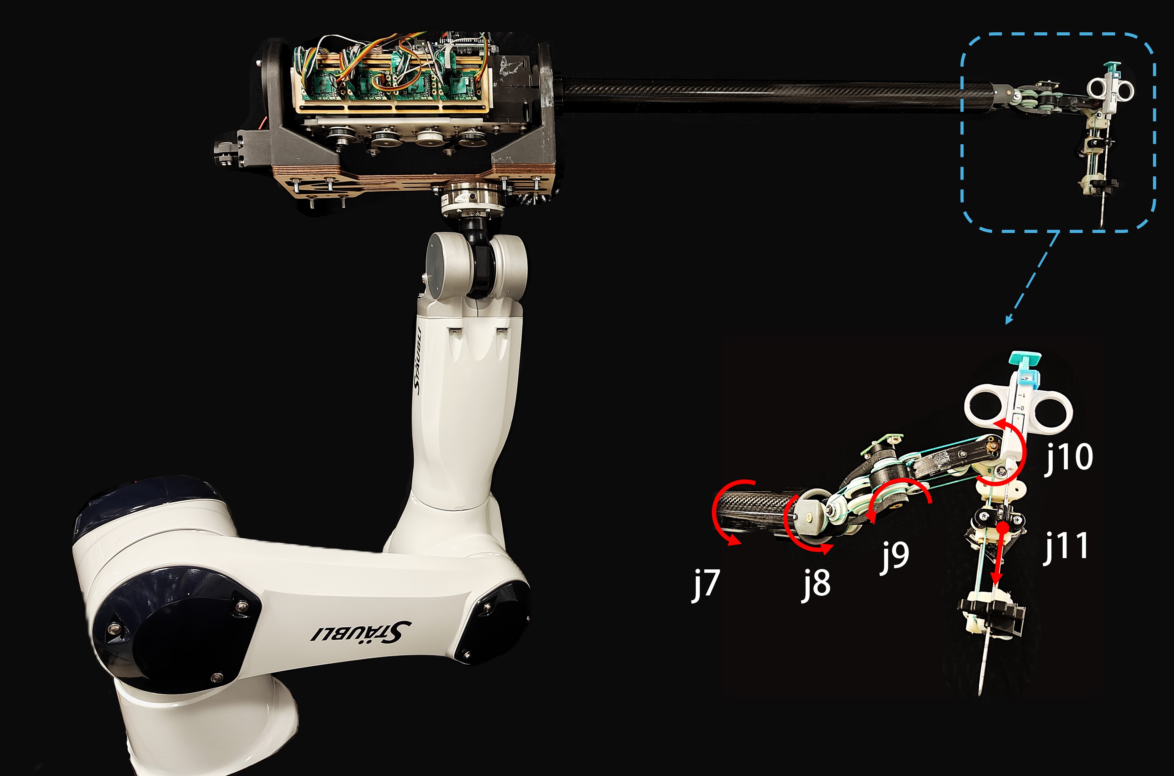
The mechanical design of our 11-DOF redundant robot integrates a flexible cable-driven 5-DOF end-effector with a Stäubli TX2-60L robot arm with 6-DOFs. We employ the 5-DOF cable-driven end-effector developed in previous works [11, 21] due to its exceptional suitability for highly dexterous, fine-needle manipulation within the confined space between the scanner bore and the patient. This end-effector comprises four revolute joints for orientation control and one independent prismatic joint for the final needle insertion. Its cable-driven design isolates the motor volume and weight from the joints, resulting in a compact structure with low inertia and enabling smooth, responsive control during needle insertion. Meanwhile, integrating a commercial 6-DOF arm into our system offers significant advantages over the previous design, including a more compact profile, an expanded workspace, and enhanced dexterity. The previous 3-DOF base was not only cumbersome but also restricted the robot’s movement due to its reliance on serial linear motion, thereby limiting its flexible deployment in real-world scenarios. In the new design, the 6-DOF arm greatly expands the workspace from 400,mm to 920,mm, provides enhanced dexterity through its six revolute joints, and maintains comparable precision and repeatability in three-dimensional space. Adopting the 6-DOF arm ultimately ensures more flexible large-scale movement during the approaching stage of needle insertion. The combined 11-DOF robot system introduces new challenges and opportunies in robot control, which are addressed in the following subsections by focusing on controlling large-scale movement and fine in-bore adjustments.
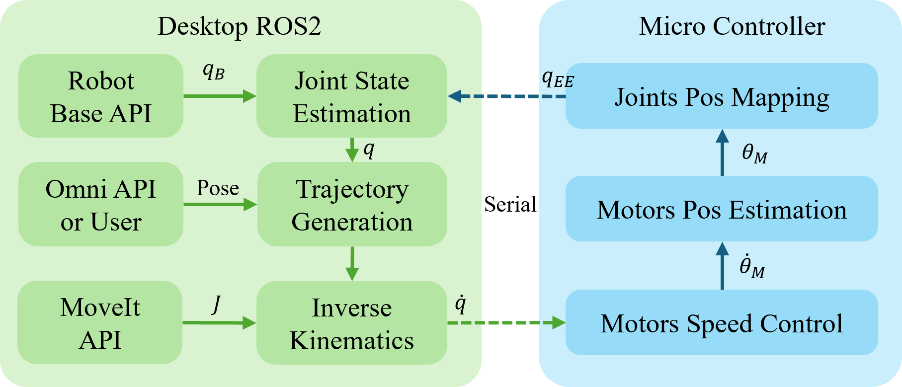
The software architecture, as illustrated in Fig. 2, is divided into high-level control and planning modules running on a desktop computer and low-level real-time embedded micro-controllers. The desired needle pose is provided either by a 3D stylus (Phantom Omni) or through user commands and is then compared with the current end-effector pose. A joint velocity command is generated by the inverse kinematics solver and transmitted to the micro-controller via serial communication. The micro-controller records motor speed, estimates joint positions using the coupling matrix, and provides joint state feedback to the desktop-based state estimator. The details of the coupling matrix is given in [11], though generally speaking it is used to decouple joints that move together when cable-drive is used in a serial-link kinematics.
II-B Weighted Inverse Kinematics Controller
A weighted inverse kinematics controller is developed for our redundant 11-DOF robot, enabling the robot to accurately track the desired needle pose and users to dexterously manipulate a needle within the scanner.
Consider a robot Jacobian with joint DOFs and task DOFs, where in our application, because the last DOF of the robot is a prismatic joint for insertion and should be keep static during target tracking state; the task space degree because the needle insertion pose can be specified without considering rotation around the needle’s principal axis.
Since the joint DOFs are much larger than task space DOFs, there are infinite solutions to the inverse kinematics problem. Although a robust pseudo-inverse or a singular value decomposition scheme is often taken to form the inverse, these do not leverage task-level information. Instead, we propose to define the priority of joints according to the characteristics of the robot platform and task requirement. To achieve this, we assign a positive-definite diagonal weight matrix to penalize joint motions, where larger means joint motion is more costly. As a result, we formulate the problem as seeking joint velocity that minimizes a cost function combining task error and a weighted joint effort:
| (1) |
where is the generalized desired end-effector velocity and is a small damping factor. The first term is the task-space error, and the second term penalizes joint velocities (weighted by ). Taking the derivative of (1) w.r.t and setting it to zero yields
| (2) |
Rearranging terms gives:
| (3) |
Since is positive definite and , the matrix is semi-positive definite, then the matrix is invertible. Thus, solving (3) gives us
| (4) |
which is the damped weighted least-squares solution. By a change of variables, we can further rearrange (4) as
| (5) |
where is the identity matrix. From (5), we define the weighted damped pseudo-inverse as
| (6) |
As a result, we obtain
| (7) |
Note that if becomes an identity matrix, means equal weights in joints, then is the robust pseudo-inverse obtain from Levenberg–Marquardt algorithm. Additionally, the damping mainly acts near singular configurations – it adds inside the inverse, keeping it well-conditioned and robust to singularities. leads to the ordinary Moore-Penrose pseudo-inverse , the end-effector velocity is accurately achieved at the cost of numerical stability; for larger , small task errors are allowed in exchange for smaller/faster joint motions.
Weighting different joints unequally can dramatically affect which joints move to accomplish an end-effector motion. Due to the existence of term in , joints with smaller weights appear with larger in , so they contribute more to the solution. Different weight policies have varying impacts on end-effector tracking accuracy, speed, and stability. For example, if base joints are heavily penalized while distal joints are cheap to move, the IK solution will favor using the wrist/end joints for error correction. The end-effector can adjust orientation and fine position very accurately since the low-weight distal joints will swiftly respond to small target changes. The robot’s base will remain relatively steady, and it moves only if the distal joints alone cannot achieve the target. This yields a stable base. However, for large motions or distant targets, relying only on the distal joints may limit speed. The end-effector might initially lag behind a rapidly moving target because the base, which could provide large workspace motion, is slow to engage. Thus, this weight policy could give excellent accuracy in fine tracking and orientation control and a very smooth/stable base, but it may slow down large translations of the end-effector.
To apply (7) to the local controller and minimize the difference between the estimated end-effector pose and the target pose, we define two Cartesian orientation errors by computing the axis–angle difference between the z-axes of the current and target end-effector poses. Combined with the Cartesian position errors, the overall pose error is expressed as follows:
| (8) |
where , . , are target and current positions. and are the Z-axis vectors of the rotation matrix of target and current pose.
II-C Achieving Subgoals with Null-space Control
The robot platform we developed is redundant, having 11 DOFs to track the 5-DOF target. We can utilize the redundant joints to achieve subgoals besides the primary task. A key tool is the null-space projection matrix. Using the definition of the robust weighted pseudoinverse in (6), We define the projector onto the null-space of as:
| (10) |
where is the identity matrix. For any joint velocity , the component lies in the null-space of because . Thus , meaning produces no end-effector motion.
The dimension of the null-space equals . In our example, active joints and task DOFs, and we assume . Therefore, the null-space has dimension . This means there are 5 independent degrees of freedom available for secondary objectives.
The property of projection matrix gives us flexibility to define subgoals to achieve according the specific task requirement and environment without affecting the primary task. In our application, we aim at dexterous in-bore manipulation of the robot and thus adopt modified version of Yoshikawa manipulability in null-space control, which is defined as
| (11) |
A geometry interpretation of (11) is the volume of the velocity ellipsoid that the robot can achieve at the end-effector. In our case, high manipulability occurs when the joints are arranged so that each contributes independently to moving the end-effector. To maximize the manipulability with null-space control, the joint velocity is defined as
| (12) |
III EXPERIMENTS
III-A Parameter Selection
The parameters used in our experiments are as follows: the weighted Jacobian-based control gain , the null-space control gain , where is identity matrix. The damping factor in (6) is . We define three diagonal matrices, each corresponding to a different weight policy: where is zero matrix. Here, corresponds to a High–Low policy—high penalty weights on the robot base and low penalty weights on the end-effector—while and represent High–High and Low–High policies, respectively.
III-B Weighted Jacobian-based Inverse Kinematics
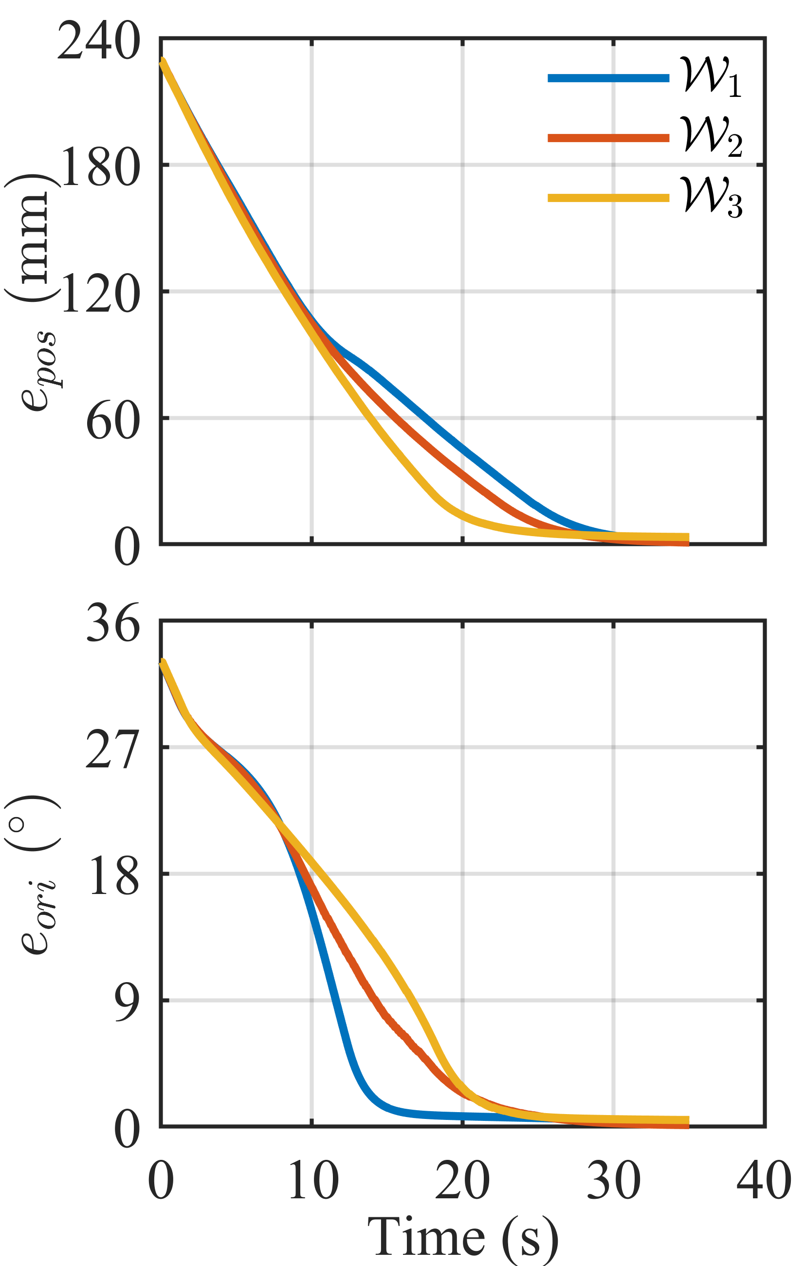
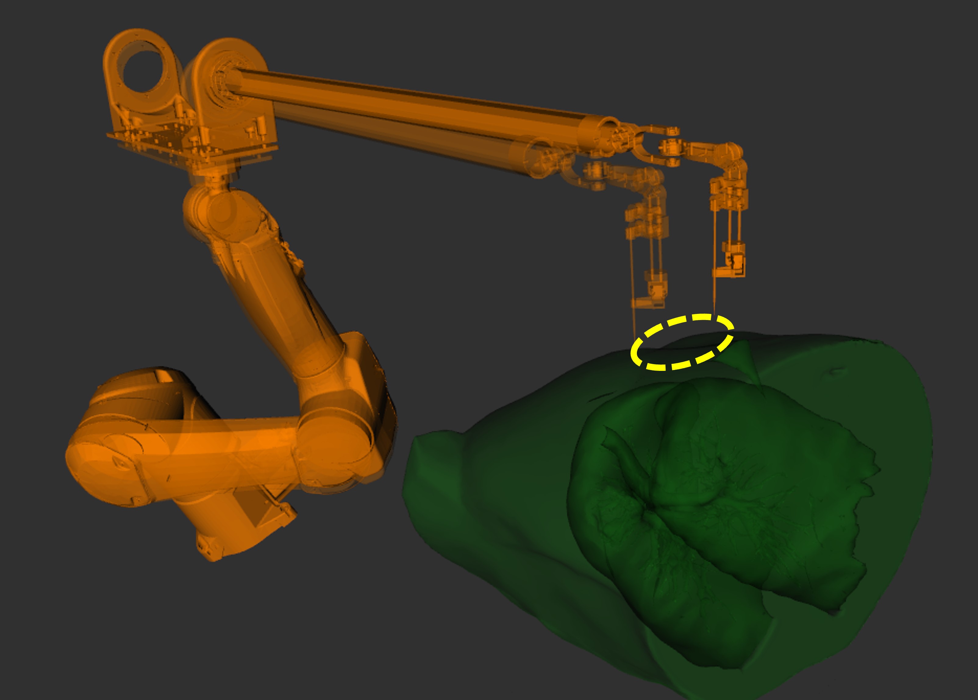
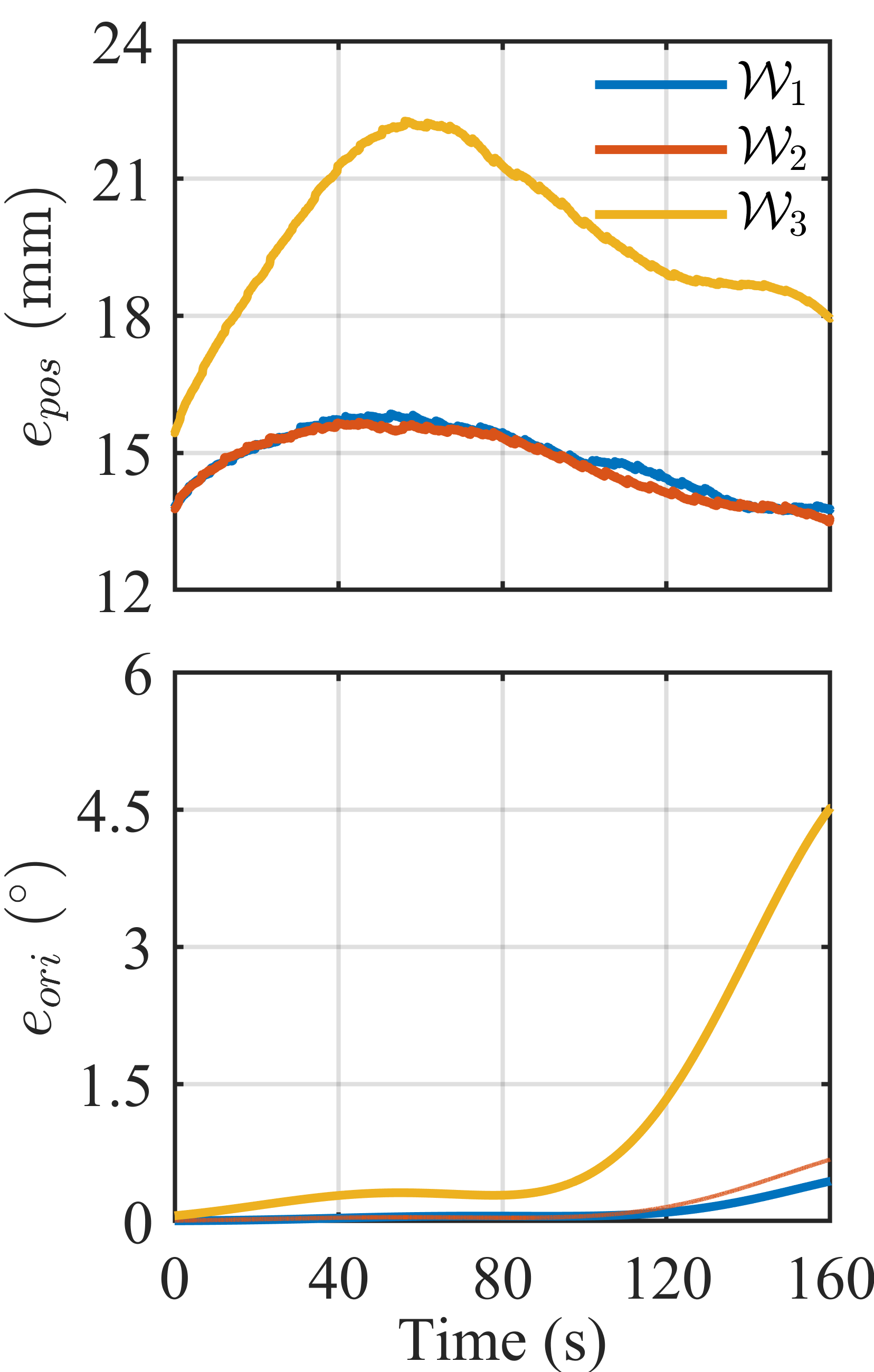
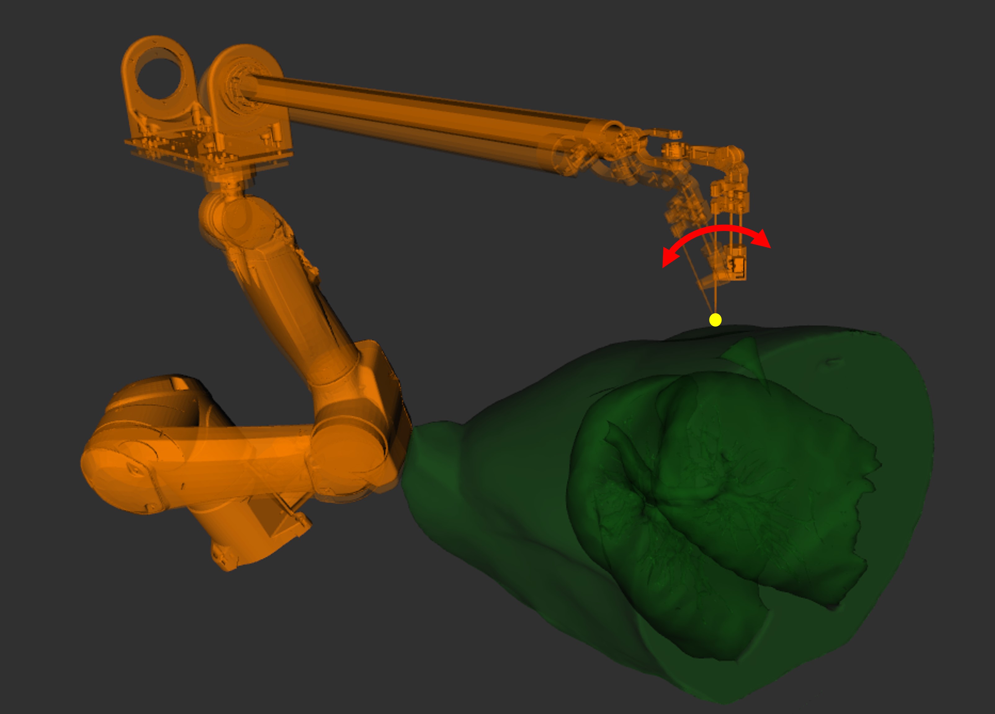
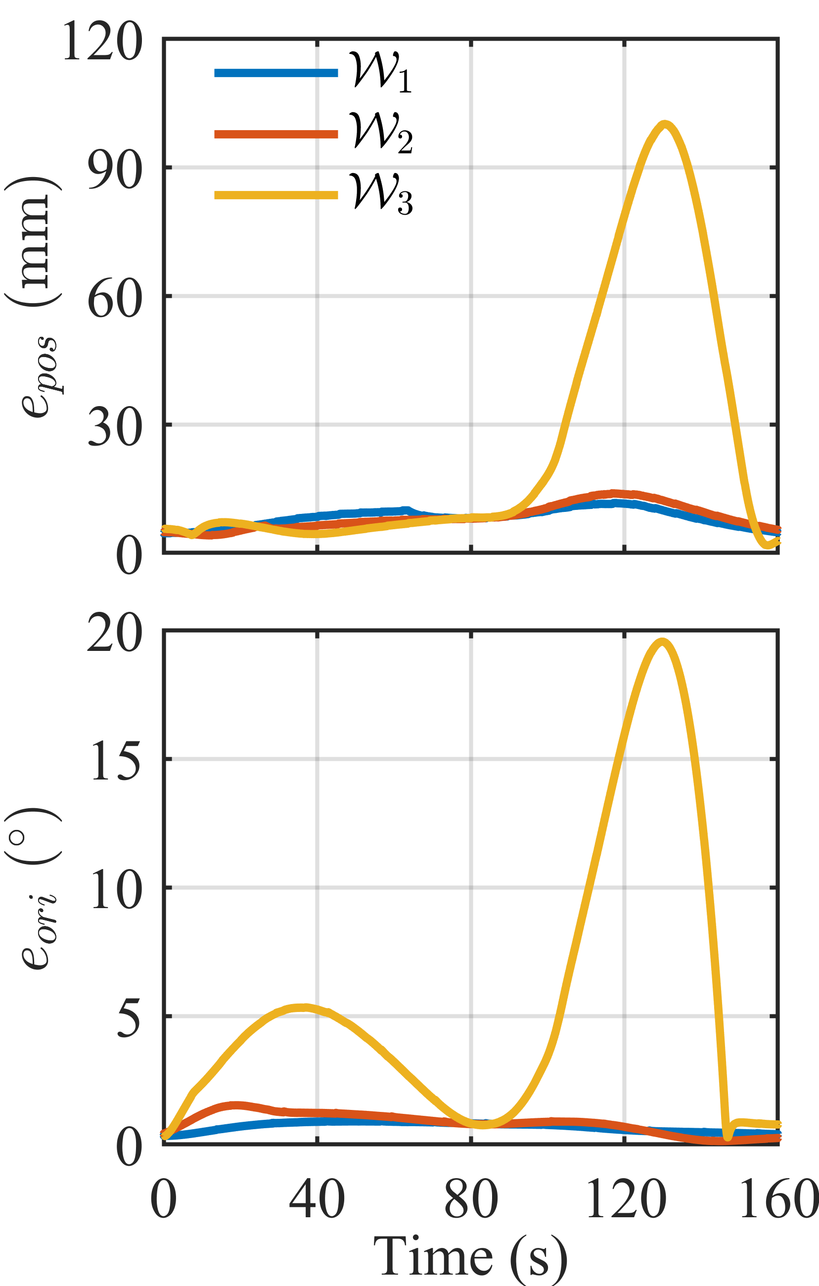
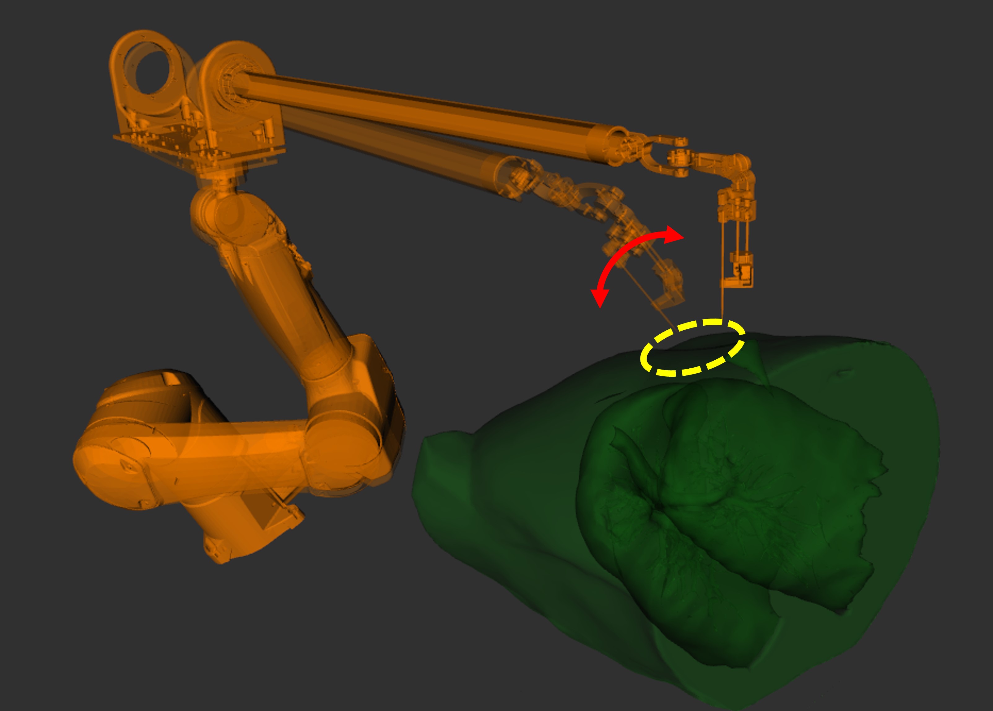
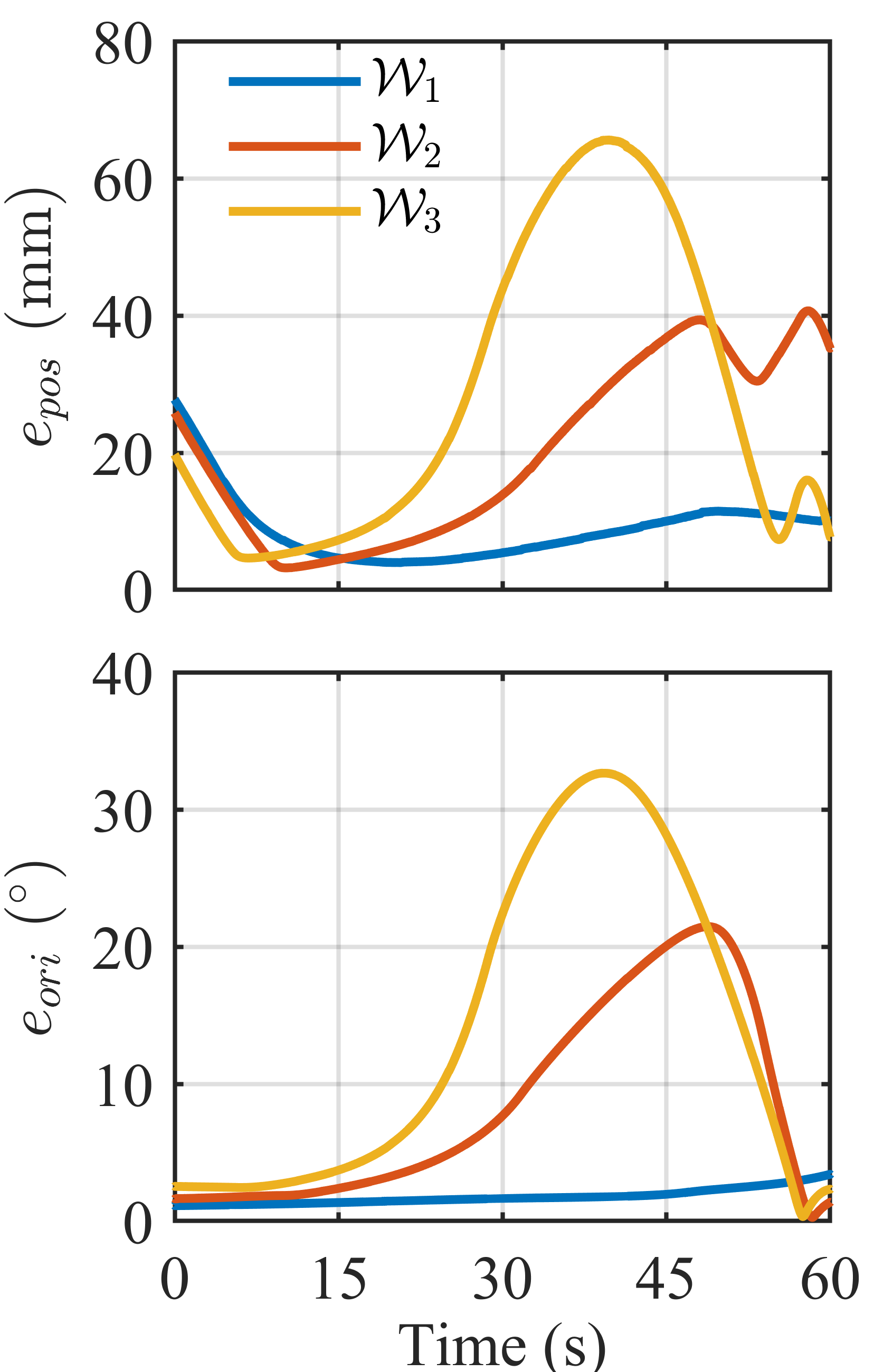
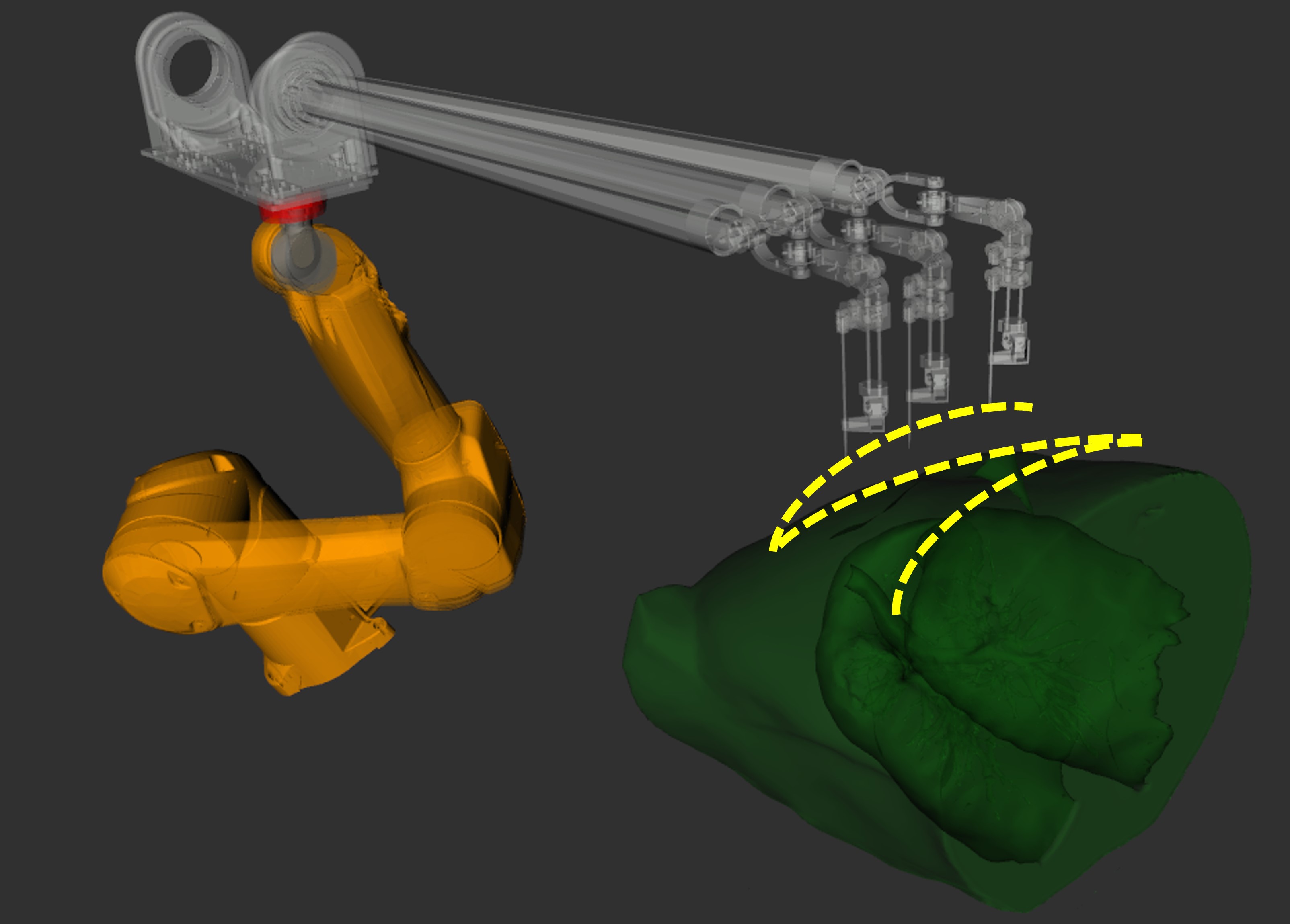
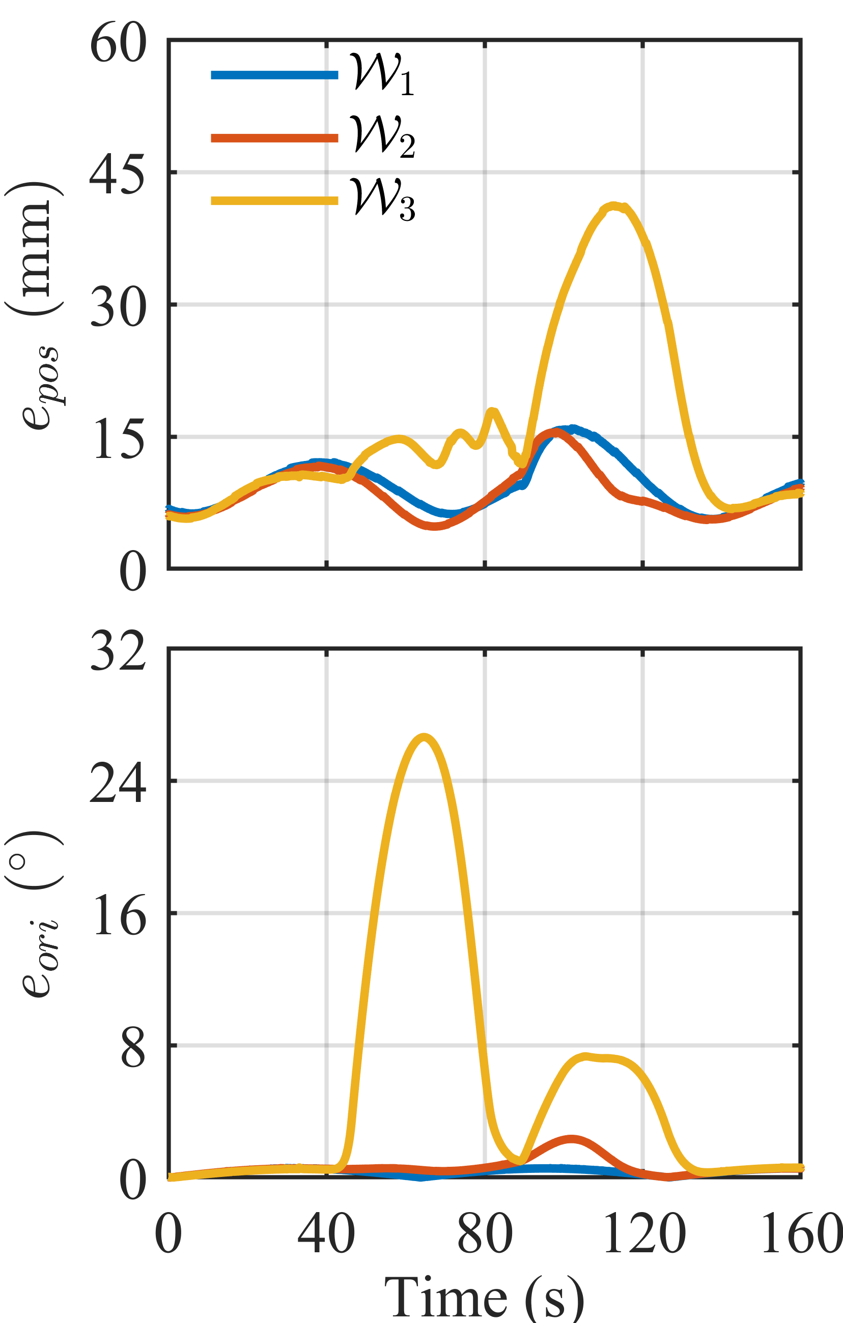
We first evaluate the weighted inverse Jacobian-based control under three different weight policies by examining five representative trajectories. The tracking performance is characterized by the mean position and orientation errors, as reported in Fig. 3 and Table. I. During the experiments, the robot platform is controlled to track five typical trajectory scenarios, as shown in the first row of Fig. 3. The trajectories include:
-
1.
Reaching In-Bore: Step response for a fixed pose;
-
2.
In-Bore Positioning: Circular motion in position with a radius of 5 cm;
-
3.
In-Bore RCM: Orientation tracking with a maximum angular deviation of 45∘ from the center;
-
4.
In-Bore Pose Tracking: Combined position and orientation motion, involving a 5 cm-radius circular trajectory and a maximum angular deviation of 45∘ from the center;
-
5.
In-Bore Z-Trajectory: A “z-shape” path (position and orientation) covering a 20 cm 20 cm area in the -plane, a maximum height difference of 5,cm in , and a maximum angular deviation of 45∘.
These trajectories can be categorized into two primary stages during a clinical CT-guided needle insertion procedure. Reaching In-Bore corresponds to the initial large-scale gross motion of the robot platform from outside the bore to inside the imaging bore to approach the patient. This stage faces fewer constraints and requires a faster response to minimize overall operation time. The other trajectories represent the in-bore fine manipulation and adjustment of the needle, which demands accurate and careful movement within the narrow imaging bore and the patient’s chest. By comparing the real-time robot end-effector trajectories obtained via forward kinematics with the desired trajectories, we observe different performances for the three weight policies across these five scenarios.
| Trajectory | Metric | Weight Policy | ||
|---|---|---|---|---|
| Reaching In-Bore | (s) | 22.3 | 20.2 | 16.6 |
| (s) | 26.5 | 24.4 | 20.7 | |
| (mm) | 2.0 | 0.8 | 3.5 | |
| (∘) | 0.4 | 0.1 | 0.5 | |
| In-Bore | ||||
| Positioning | (mm) | 14.9 | 14.8 | 19.8 |
| (∘) | 0.1 | 0.1 | 1.0 | |
| In-Bore | ||||
| RCM | (mm) | 8.3 | 8.4 | 25.3 |
| (∘) | 0.7 | 0.8 | 5.7 | |
| In-Bore Pose | ||||
| Tracking | (mm) | 8.8 | 20.1 | 28.2 |
| (∘) | 1.8 | 8.5 | 13.8 | |
| In-Bore | ||||
| Z-Trajectory | (mm) | 9.4 | 8.6 | 16.1 |
| (∘) | 0.3 | 0.6 | 5.8 |
III-B1 Reaching In-Bore
achieves the shortest rise time and settling time in position, reducing these times by up to and compared with and , respectively. This is due to the lower penalty weight on the robot base in , which facilitates large-scale end-effector motion. Despite this faster response, maintains acceptable steady state position and orientation errors, suggesting that rapid gross movement can be safely applied when approaching the patient inside the imaging bore. Conversely, achieves the shortest rise and settling times in orientation but the longest in position. exhibits the least steady-state position and orientation errors overall.
III-B2 In-Bore Manipulation
proves more favorable by providing the highest orientation accuracy in all trajectories and the highest or second-highest position accuracy. Because the robot base handles -axis motions at this stage and the end-effector tracks orientation, ’s lower penalty on end-effector joints allows it to respond more quickly to control commands and precisely track the desired orientation. In contrast, shows the lowest accuracy during fine in-bore motion. Its lower penalty on robot base movement leads to overshoot in small-scale movements, making it nearly unusable for this stage due to its large errors. Additionally, as seen in Fig. 3, experiences spikes in orientation and position errors, arising from singularities during prolonged orientation tracking. This occurs because tends to compensate more with robot base movement, increasing the likelihood of encountering singular joint configurations.
In summary, a low penalty weight on the robot base (like ) leads to faster tracking response and is advantageous during the gross-motion phase of needle insertion. Conversely, a low penalty weight on the end-effector (like ) achieves better tracking accuracy and is more suitable for fine needle manipulation within the confined imaging bore.
III-C Null-space Controller
Next, we demonstrate the effect of null-space control by comparing the robot arm configurations with and without null-space control. As shown in Fig. 4, the end-effector follows a circular trajectory with a 30 cm radius. Without null-space control, the robot’s joint configuration tends to stretch into a straight-line posture, resulting in reduced manipulability and increased end-effector deviation from the trajectory due to singularities. In contrast, with null-space control, the configuration remains bent, leading to higher manipulability and reduced tracking deviation. Figure 5 presents the Yoshikawa manipulability measure for both methods, demonstrating that the robot with null-space control achieves a higher manipulability value.
We also investigate the impact of null-space control parameters, namely the null-space control gain and damping factor , on tracking accuracy. The step response of a fixed target pose is used as an example, as shown in Fig. 6. An increase in steady-state position error is observed with larger values of and . is introduced for numerical stability in the Levenberg-Marquardt (LM) algorithm. However, an excessively large can introduce numerical errors in the computation of the projection matrix, leading to a null-space that is not strictly orthogonal. Consequently, the primary task tracking is affected, resulting in a larger tracking error. Additionally, if the secondary task is assigned an excessively high relative to the primary task gain , the manipulator may move aggressively in the null-space, thereby degrading the tracking performance of the primary task. Thus, selecting an appropriate damping factor requires balancing numerical stability of computing pseudo-inverse and the numerical error in computing the projection matrix. Moreover, a properly tuned null-space control gain is essential to ensure that the primary task remains unaffected.
III-D Teleoperation Demonstration
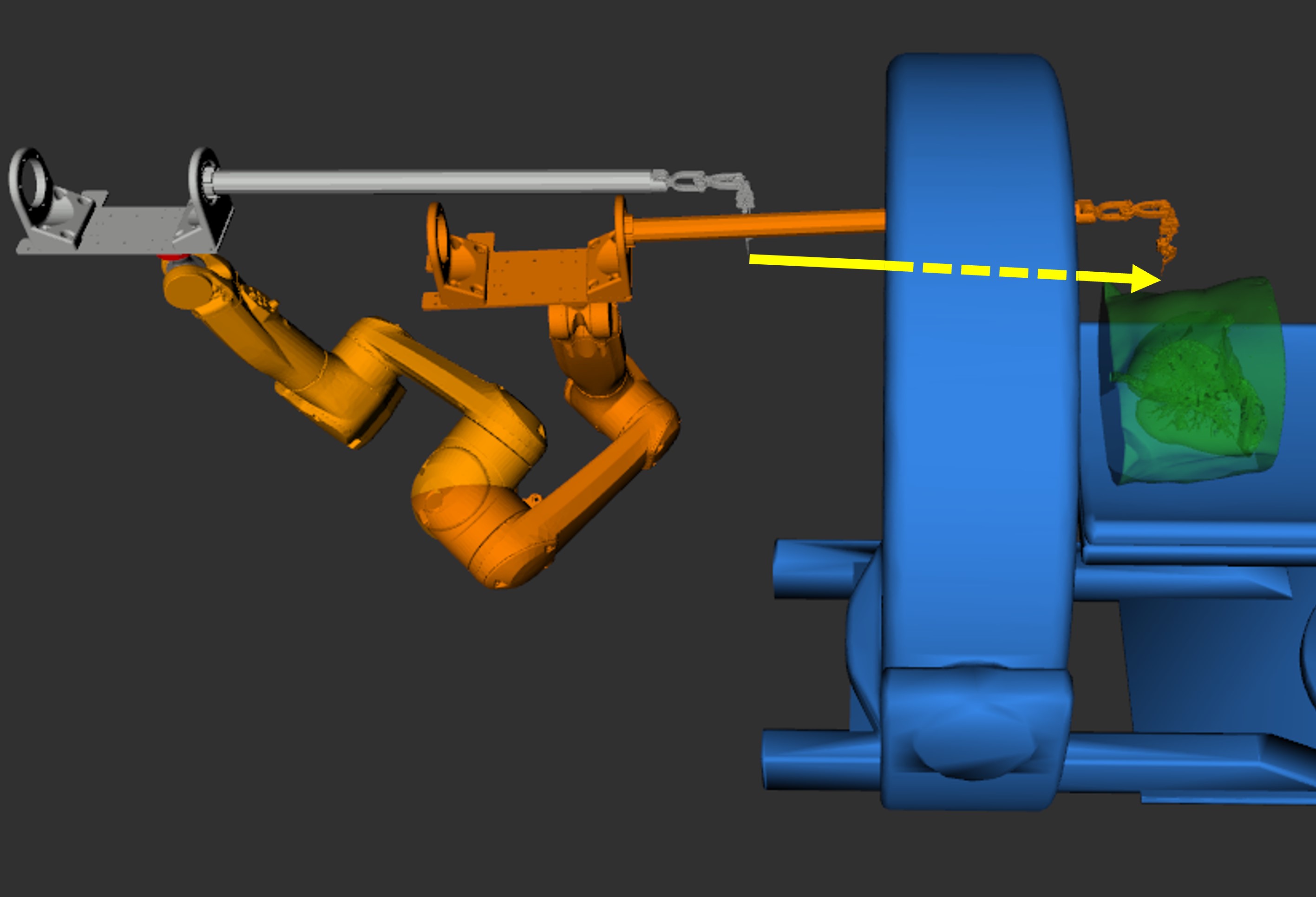
Finally, we validate the robot platform and control algorithm through a teleoperation test. In this experiment, the operator uses a Phantom Omni device to provide the target pose for the robot end-effector’s needle tip. The workflow, illustrated in Fig. 7, consists of three stages: (1) maneuvering the end-effector from the setup position outside the bore to inside the bore; (2) adjusting the needle’s position and orientation within the imaging bore; and (3) inserting the needle into the target location. This test demonstrates the capability of our robotic platform to accurately achieve target positions and successfully insert the needle into the target under teleoperated control.
IV CONCLUSIONS
We have developed an 11-DOF robot and derived a controller that leverages its kinematic hyper-redundancy to enable dexterous needle manipulation in constrained CT biopsy procedures. By employing a weighted Jacobian-based control approach, the system can selectively focus on either the end-effector or the robot base according to a two-stage priority scheme, thereby facilitating a faster response or higher accuracy as needed. Additionally, the use of null-space control allows us to set subgoals—such as optimizing manipulability and maintaining a desired pose of end-effector—enhancing the robot’s adaptability in the confined imaging bore while preserving sufficient dexterity for needle insertion and manipulation. We validate our methods through extensive experiments and demonstrate the system in a teleoperated scenario. Future work will focus on integrating a haptic feedback mechanism to guide the operator toward the target during insertion and compensate for the patient’s respiratory cycle.
Acknowledgments
This work was funded by the National Institutes of Health Award 1R01CA278703-01.
References
- [1] A. Saifuddin, V. Palloni, H. du Preez, and S. E. Junaid, “the current status of ct-guided needle biopsy of the spine,” Skeletal Radiology, vol. 50, pp. 281–299, 2021.
- [2] B. S. Chhikara, K. Parang et al., “Global cancer statistics 2022: the trends projection analysis,” Chemical Biology Letters, vol. 10, no. 1, pp. 451–451, 2023.
- [3] W. D. Travis, E. Brambilla, M. Noguchi, A. G. Nicholson, K. Geisinger, Y. Yatabe, Y. Ishikawa, I. Wistuba, D. B. Flieder, W. Franklin et al., “Diagnosis of lung cancer in small biopsies and cytology: implications of the 2011 international association for the study of lung cancer/american thoracic society/european respiratory society classification,” Archives of Pathology and Laboratory Medicine, vol. 137, no. 5, pp. 668–684, 2013.
- [4] C. C. Wu, M. M. Maher, and J.-A. O. Shepard, “Ct-guided percutaneous needle biopsy of the chest: preprocedural evaluation and technique,” American Journal of Roentgenology, vol. 196, no. 5, pp. W511–W514, 2011.
- [5] S. Leng, “Radiation dose in ct–guided interventional procedures: Establishing a benchmark,” pp. 158–159, 2018.
- [6] Y.-W. Chiu, Y.-H. Kao, M. J. Simoff, D. E. Ost, O. Wagner, J. Lavin, R. A. Culbertson, and D. G. Smith, “Costs of biopsy and complications in patients with lung cancer,” ClinicoEconomics and Outcomes Research, pp. 191–200, 2021.
- [7] Y. Zhang, L. Shi, M. J. Simoff, O. J Wagner, and J. Lavin, “Biopsy frequency and complications among lung cancer patients in the united states,” Lung cancer management, vol. 9, no. 4, p. LMT40, 2020.
- [8] R. S. Wiener, L. M. Schwartz, S. Woloshin, and H. G. Welch, “Population-based risk for complications after transthoracic needle lung biopsy of a pulmonary nodule: an analysis of discharge records,” Annals of internal medicine, vol. 155, no. 3, pp. 137–144, 2011.
- [9] C. Lanza, S. Carriero, E. F. M. Buijs, S. Mortellaro, C. Pizzi, L. V. Sciacqua, P. Biondetti, S. A. Angileri, A. A. Ianniello, A. M. Ierardi et al., “Robotics in interventional radiology: review of current and future applications,” Technology in Cancer Research & Treatment, vol. 22, p. 15330338231152084, 2023.
- [10] F. J. Siepel, B. Maris, M. K. Welleweerd, V. Groenhuis, P. Fiorini, and S. Stramigioli, “Needle and biopsy robots: A review,” Current Robotics Reports, vol. 2, pp. 73–84, 2021.
- [11] D. Schreiber, Z. Yu, T. Henderson, D. Chen, A. Norbash, and M. C. Yip, “Crane: A redundant, multi-degree-of-freedom computed tomography robot for heightened needle dexterity within a medical imaging bore,” IEEE Transactions on Robotics, 2024.
- [12] S. Levy, S. N. Goldberg, I. Roth, M. Shochat, J. Sosna, I. Leichter, and S. Flacke, “Clinical evaluation of a robotic system for precise ct-guided percutaneous procedures,” Abdominal radiology, vol. 46, no. 10, pp. 5007–5016, 2021.
- [13] A. L. Gunderman, M. Musa, B. O. Gunderman, F. Banovac, K. Cleary, X. Yang, and Y. Chen, “Autonomous respiratory motion compensated robot for ct-guided abdominal radiofrequency ablations,” IEEE Transactions on Medical Robotics and Bionics, vol. 5, no. 2, pp. 206–217, 2023.
- [14] N. Hungr, I. Bricault, P. Cinquin, and C. Fouard, “Design and validation of a ct-and mri-guided robot for percutaneous needle procedures,” IEEE transactions on robotics, vol. 32, no. 4, pp. 973–987, 2016.
- [15] D. A. Schreiber, D. B. Shak, A. M. Norbash, and M. C. Yip, “An open-source 7-axis, robotic platform to enable dexterous procedures within ct scanners,” in 2019 IEEE/RSJ International Conference on Intelligent Robots and Systems (IROS). IEEE, 2019, pp. 386–393.
- [16] B. Schulz, K. Eichler, P. Siebenhandl, T. Gruber-Rouh, C. Czerny, T. J. Vogl, and S. Zangos, “Accuracy and speed of robotic assisted needle interventions using a modern cone beam computed tomography intervention suite: a phantom study,” European radiology, vol. 23, pp. 198–204, 2013.
- [17] T. Komaki, T. Hiraki, T. Kamegawa, T. Matsuno, J. Sakurai, R. Matsuura, T. Yamaguchi, T. Sasaki, T. Mitsuhashi, S. Okamoto et al., “Robotic ct-guided out-of-plane needle insertion: comparison of angle accuracy with manual insertion in phantom and measurement of distance accuracy in animals,” European Radiology, vol. 30, pp. 1342–1349, 2020.
- [18] H. J. Won, N. Kim, G. B. Kim, J. B. Seo, and H. Kim, “Validation of a ct-guided intervention robot for biopsy and radiofrequency ablation: experimental study with an abdominal phantom,” Diagnostic and Interventional Radiology, vol. 23, no. 3, p. 233, 2017.
- [19] I. M. Spenkelink, J. Heidkamp, Y. Avital, and J. J. Fütterer, “Evaluation of the performance of robot assisted ct-guided percutaneous needle insertion: Comparison with freehand insertion in a phantom,” European journal of radiology, vol. 162, p. 110753, 2023.
- [20] Y. J. Kim, J. H. Seo, H. R. Kim, and K. G. Kim, “Impedance and admittance control for respiratory-motion compensation during robotic needle insertion–a preliminary test,” The International Journal of Medical Robotics and Computer Assisted Surgery, vol. 13, no. 4, p. e1795, 2017.
- [21] D. Schreiber, Z. Yu, H. Jiang, T. Henderson, G. Li, J. Yu, R. Zhu, A. M. Norbash, and M. C. Yip, “Crane: a 10 degree-of-freedom, tele-surgical system for dexterous manipulation within imaging bores,” in 2022 International Conference on Robotics and Automation (ICRA). IEEE, 2022, pp. 5487–5494.