pageheadfoot
Physically Large Apertures for Wireless Power Transfer:
Performance and Regulatory Aspects
Physically Large Apertures for Wireless Power Transfer:
Performance and Regulatory Aspects
Abstract
Wireless power transfer (WPT) is a promising service for the Internet of Things (IoT), providing a cost-effective and sustainable solution to deploy so-called energy-neutral devices on a massive scale. The power received at the device side decays rapidly with the distance from a conventional transmit antenna with a physically small aperture. New opportunities arise from the transition from conventional far-field beamforming to near-field beam focusing. We argue that a “physically large” aperture, i.e., large w.r.t. the distance to the receiver, enables a power budget that remains practically independent of distance. Distance-dependent array gain patterns allow focusing the power density maximum precisely at the device location, while reducing the power density near the infrastructure. The physical aperture size is a key resource in enabling efficient yet regulatory-compliant WPT. We use real-world measurements to demonstrate that a regulatory-compliant system operating at sub-10GHz frequencies can increase the power received at the device into the milliwatt range. Our empirical demonstration shows that power-optimal near-field beam focusing inherently exploits multipath propagation, yielding both increased WPT efficiency and improved human exposure safety in real-world scenarios.
Index Terms:
Beam focusing, channel measurements, energy-neutral, Internet of Things, near-field, wireless power transferI Introduction
The use of the Internet of Things (IoT) is expected to grow exponentially in applications such as healthcare, logistics, and smart cities. This brings significant sustainability challenges, particularly regarding the ecological impact of electronics manufacturing, and the ecotoxicity of batteries [1]. Batteryless energy-neutral (EN) device technology tackles these issues by miniaturizing circuits, reducing waste, and extending device lifespans [2, 3]. Radio frequency (RF) wireless power transfer (WPT) technology can power these EN devices, eliminating the need for batteries. This, however, requires an infrastructure capable of providing efficient WPT as a service on a massive scale.
In this article, we show that physically large apertures—meaning apertures that are large relative to the propagation distances of interest—are advantageous for WPT. Specifically, we explain why the use of large apertures results in improved WPT efficiency, i.e., path gain (PG),111The PG is defined as the ratio of power received at the device to total power radiated by all transmit antennas. and in lower power densities close to the array – which is important in order to stay within regulatory limits on human exposure. Physically large apertures naturally arise with the large and distributed antenna arrays that are envisioned for sixth generation (6G) systems, when operating at “low” carrier frequencies especially in the “golden” bands below [4].
To appreciate the main phenomenology, we consider an introductory example comparing two systems. The first system uses a physically large -uniform rectangular array (URA) of -wavelength spaced antennas, operating at (cf. Fig. 1), and the second system uses a physically small -URA of -wavelength spaced antennas operating at . In both systems the array radiates of total power and beamforms power to an EN device located away from the array, in its boresight direction. Conjugate beamforming (maximum-ratio transmission) [6] is used, assuming perfect channel state information (CSI) at the array. Importantly, such beamforming inherently accounts for near-field effects, i.e., the fact that the wavefronts are curved.
Figures 2 a) and 2 b) show both the path gain in and the power density in , as a function of spatial location for these two systems, when using near-field beam focusing given the perfect line-of-sight (LoS) channel as CSI. We note the following:
-
•
For a given transmitted power, the power density at the EN device is the same in both systems. Hence, the harvested power (and WPT efficiency) will be identical provided that the EN device has the same effective receive aperture (of ) both at and . However, this requires the EN device antenna to have a larger directivity than the device, which in turn requires some form of physical or electronic beam steering.
-
•
In the physically small system, the maximum power density lies close to the transmitting array. In fact it is also much larger than for the case. At , the maximum power density is shifted towards the EN device, enabled through the range-dependent array gain pattern222Demonstrated later using real-world measurements in Fig. 3 b).[7] of the physically large aperture in the near field.
Both these observations are consequences of the physically large aperture of the system. While both systems have the same electrical aperture—meaning aperture size relative to the wavelength—the physical aperture of the system is times larger in each dimension than that of the system. Note that the angular beamwidth is the same in both systems; this is because their electrical aperture in wavelengths (and number of antennas) is the same.
Qualitatively, the power densities will look the same at and , if the geometry is scaled correspondingly. This is a consequence of the scaling invariance of the wave equation. Specifically, suppose we move the EN device ten times closer to the array ( meters away) and scale the dimensions in Fig. 2 a) by . We then obtain qualitatively the same behavior as in Fig. 2 b): the maximum power density occurs near to the device. Also, the power density is higher in this case than in Fig. 2 b), which leads to the same harvested power, even without the need for a directional antenna at the device. But the ultimate consequence is a reduction of the achieved range by a factor of ten, which makes the system impractical.
The presence of multipath propagation effectively increases the physical aperture: the multipath propagation at specular surfaces can be modeled as virtual mirror arrays (cf. Fig. 1). To illustrate this phenomenon, we consider the system operating in the hallway scenario schematically depicted in Fig. 1. Figures 2 c) and 2 d) show the power density separately for two different multipath components, and Fig. 2 e) shows the power density resulting from all multipath components and the LoS path combined. We observe the following:
-
•
The radiated waves from all antennas, after undergoing multipath propagation, combine constructively at the EN device. This is accomplished by the conjugate beamforming, which automatically accounts for multipath propagation and near-field effects.
-
•
The presence of multipath effectively enlarges the physical aperture, narrowing the focal regtion, and shifting the maximum power density to the close vicinity of the EN device in Fig. 2 e).
In summary, a physically large aperture leads to a decreasing power density near the array and a maximum power density close to the device. This should be contrasted with physically small apertures, that exhibit an increasing power density near the array.
The choice of operating frequency is fundamentally tied to the realizable physical aperture size for both the infrastructure and the device. To maintain a constant physical aperture while increasing the frequency, the number of antennas in the array must be increased. Although this approach can potentially improve both the WPT efficiency and the achievable range, there are fundamental limitations to such frequency scaling: (i) The focal region’s effective width narrows, which eventually makes the beam-acquisition procedure prohibitively difficult. (ii) A constant-aperture receive antenna becomes more directive at higher frequencies, restricting efficient reception to specific directions, or requiring beam steering, which is considered impractical at an EN device. All of these factors must be carefully considered when designing efficient and scalable WPT systems.
Supported by the real-world synthetic aperture measurements in Fig. 1, we validate the advantages of physically large apertures for WPT, leading to the following contributions: In Section II-A, we investigate regulatory limits and show how physically large apertures can aid regulatory compliance. If the size of the aperture is sufficiently large, the global maximum of power density can be shifted to the location of the EN device. We derive the achievable power budgets w.r.t. human exposure regulations and illustrate that operating at sub-10 GHz frequencies can increase the receivable power from the microwatt to the milliwatt range. In Section II-B, we show that this feature of physically large apertures is enabled through range-dependent near-field gain pattern. In Section II-C, we demonstrate that power-optimal beam focusing naturally exploits multipath propagation. This effectively enlarges the transmit aperture [8], improving both the WPT efficiency and regulatory compliance. In Section III, we show that unprecedented receive power levels will necessitate new integrated circuit architectures that enable EN devices to operate efficiently over a wide dynamic range. In Sec. IV, we address fundamental challenges of EN device operation: First, the initial access problem that arises before the first interaction with batteryless EN devices, and second, the problem of self-interference mitigation, which aims at separating a weak backscatter signal from a strong carrier emitter.
II The Potential of Physical Aperture
Being large w.r.t. the propagation distances of interest, physically large apertures typically operate in the array near-field. Unlike the range-independent far-field (i.e., plane-wave) array gain pattern, the near-field (i.e., spherical-wave) array gain pattern becomes range-dependent [9, p. 25 f.]. In a communication context, this range-dependence enables spatial separation of users [10, 11]. However, we show that it also significantly aids WPT with physically large apertures through reduced interference, better regulatory compliance and higher power budgets.
II-A Power Density Regulations and Power Budgets
WPT must be performed in compliance with regulations. This affects the receivable power on the device side. Regulations typically limit two quantities: maximum power density and equivalent isotropically radiated power (EIRP). The European Council Recommendation 1999/519/EC [12] limits the maximum power density allowed in the European Union, while the Federal Communications Commission (FCC) 47 CFR §1.1310 limits the maximum power density allowed in the United States. The reference levels in the former, and maximum permissible exposure in the latter, limit the power density at a maximum of for frequencies higher than , and , respectively. The limitation of the maximum power density is motivated by human exposure safety. It is a useful quantity for regulating near-field beam focusing, which can be easily evaluated spatially, and has therefore received attention in related work on WPT in distributed radio architectures [2].
Considering only the device side and assuming a power density limit of , the maximum receivable power would depend only on the effective aperture of the receive antenna.444Note that the frequency-dependency of the Friis transmission equation is solely due to commonly being frequency-dependent (see Table I). Under this assumption, an EN device equipped with an isotropic receive antenna could optimally attain the maximum receivable powers listed in Table I. As the table shows, WPT at sub-10 GHz frequencies can increase the maximum regulatory-compliant receive power from what was conventionally located in the microwatt range [1, 11] to the milliwatt range.
| Frequency | Isotropic antenna | |
|---|---|---|
| * | ||
*In
[12]
decreases linearly with below .
In FCC 47 CFR §1.1310 decreases linearly with below .
We evaluate the regulatory compliance of a single array in the hallway-scenario depicted in Fig. 1. In this scenario, we both measured CSI with a vector network analyzer (VNA) and modeled, i.e., predicted, it through an image source model [8], where mirror sources are used to represent first-order specular multipath components (SMCs). Given a reasonably high measurement signal-to-noise ratio (SNR), measured CSI is henceforth regarded as perfect CSI, while geometrically modeled CSI is denoted as predicted CSI and based on a spherical-wavefront (near-field) SMC channel model [5]. Physically large apertures aid compliance with power density limits, as near-field beam focusing positively affects the spatial distribution of the power density, particularly in the proximity of the infrastructure. To demonstrate this, we examine the impact of the individual SMCs on the WPT efficiency with the results shown in Fig. 2. It highlights how near-field beam focusing influences the regulatory compliance of physically large apertures: Using only the LoS, i.e., , a strong beam is directed towards the EN device (see Fig. 2 b). The global maximum power density is located at some distance before the device, while the power density decreases strongly towards the array. Our measurements indicate that efficient WPT can also be performed by exploiting SMCs, enabling non-LoS (NLoS) beam focusing which can bypass obstructed LoS (OLoS) conditions [13]. For instance, using component , i.e., the reflection caused by the wall in the negative -direction, still results in a strong beam that is directed towards the EN device (see Fig. 2 c). Efficient transmission remains achievable, despite lower antenna gains, longer propagation distance, and wall-induced attenuation. The latter two are losses that SMCs typically incur according to electromagnetic theory [8]. Visibility is a characteristic of physically large apertures that appears in combination with obstructions or the limited extent of reflective surfaces that produce SMCs. It demands specific attention in channel modeling [14]. Due to the limited extent of the respective wall, only a portion of the mirror source (in the positive -direction) is visible from the perspective of the EN device. As a consequence, its WPT efficiency and aperture are effectively reduced, resulting in a wider beam (see Fig. 2 d). Jointly using all SMCs in a multibeam transmission (see Fig. 2 e) leverages multipath propagation, effectively increasing the physical size of the transmit aperture, which results in:
-
i)
a narrower focal region and a shift of the global maximum of power density to the location of the EN device,
-
ii)
a higher WPT efficiency,
-
iii)
and spatially lower power density levels outside the focal region, promoting better regulatory compliance.
If the physical aperture of the transmit array becomes sufficiently large, it is possible to generate the global power density maximum at the position of the EN device (cf. [2]). Under this assumption, the power receivable by the EN device merely depends on the power density regulations and the effective aperture of its receiving antenna. Therefore, for physically large apertures, the power budget at the EN device side becomes practically independent of the distance from the infrastructure and the power budgets in Table I can be obtained. This represents a clear paradigm shift from conventional RF WPT systems operating with physically small apertures. The given scenario shows the performance peculiarities mentioned above in the example of a single physically large array. Performing WPT at , the EN device could receive up to if the array transmits at a total power of , given perfect CSI, while still adhering to the power density limit of , cf. Fig. 2 e). The resulting WPT efficiency is . This raises the question whether the use of batteries would outperform WPT in efficiency after all. When looking at the ratio of energy storage capacity over cumulative energy demand (CED) of manufacturing batteries, we find that their efficiencies are of a comparable order of magnitude [15, p. 20 ff.]. In conjunction with their low ecotoxicity and extended lifetime, batteryless EN devices may be a key enabling technology for massive IoT deployments.
II-B EIRP Limits and Near-Field Array Gain Pattern
The European Commission Decision 2006/771/EC [16] limits the EIRP in the European Union, while FCC 47 CFR §15.407 limits the EIRP in the United States, the main motivation being the reduction of interference. For single-input single-output (SISO) systems, the EIRP limit is the product of the antenna gain and the transmit power and constitutes a quantity that is practical to evaluate. While far-field array gain patterns are solely a function of elevation and azimuth angles, near-field beam focusing results in array gain patterns that are range-dependent. This aids the compliance with gain regulations as the maximum is usually focused at the device location. Thus, for near-field beam focusing with multiple-input single-output (MISO) systems, the existing regulations do not reflect how the array gain affects the EIRP. Specifically, high near-field array gains at the device position can still result in (i) low far-field array gains [9, p. 26] and (ii) very low near-field array gains close to the array. This demonstrates that near-field beam focusing reduces interference with receivers at both far and close distances. Thus, near-field beam focusing possibly necessitates adaptations to the EIRP regulations used to limit interference.
Fig. 3 depicts the resulting near-field array gain patterns [9, eq. (3.8)] when using predicted CSI and perfect CSI. Predicting CSI with the spherical-wavefront SMC channel model results in a beamformer that exploits strong first-order SMCs (see Fig. 3 a). It predominantly uses the LoS and component . There is barely any power directed to component due to its limited visibility. Any array gain pattern is upper-bounded by the number of transmit antennas, which is in our measurements. A reciprocity-based beamformer, given perfect CSI, results in power-optimal beamforming (see Fig. 3 b). It naturally exploits multipath propagation and uses the entire channel in a rich way, including higher-order SMCs and diffuse reflections. In Fig. 3 b), this is visible through some array gain that is diverted in directions other than the two dominant components of Fig. 3 a). A conventional spherical-wavefront LoS beamformer would generate an array gain of at the location of the EN device, while the reciprocity-based beamformer generates a spatial maximum of .
The far-field array gain pattern reduces to an even lower maximum of , far out [7, cf. Fig. 5], in the direction of the EN device. Spherical-wavefront beam focusing results in very low array gains close to the array and decaying array gains “behind” the EN device, which aids regulatory compliance and reduces interference. These effects become particularly strong with apertures being not only electrically large but also physically large. The wavefronts converge towards the device location.
II-C Near-Field Beam Focusing Strategies
Given perfect CSI, a reciprocity-based beamformer will always perform power-optimally. In practice, perfect CSI will never be available and deviations from the “true” channel will manifest in power losses. Taking these CSI imperfections into account, we discuss the expected efficiency of a reciprocity-based beamformer given noisy CSI, corrupted by additive spatially white Gaussian noise. Using the channel SNR to express the quality of CSI, its efficiency follows three asymptotic regimes (see Fig. 4):
In the low-SNR regime, CSI has a very low quality as it is dominated by noise. In this regime, depending on the random CSI realizations, the of a reciprocity-based beamformer is Rayleigh distributed and it performs on average no more efficient than an equivalent SISO system that uses only a single transmit antenna out of the antennas within the URA. This SISO path gain () may be regarded as a performance baseline. However, if all antennas are used, the power density at the URA is reduced for the benefit of regulatory compliance. The expected efficiency of the distribution is augmented by symmetric confidence intervals for which one random realization of is located within the interval with a confidence level , i.e., the probability . Fig. 4 shows the intervals computed for confidence levels . Within the confidence interval, a gain of up to can be attained over which corresponds to a “random” beamformer given multiple different random beamforming weight realizations and is achievable regardless of the number of antennas used. In the linear regime, the PG of a reciprocity-based beamformer is Gaussian distributed and its expected efficiency increases linearly with the SNR of the CSI while the relative PG variance decreases. Eventually, in the high-SNR regime, the efficiency (i.e., the PG) stays Gaussian distributed and saturates at the MISO PG, representing the upper bound on efficiency and leveraging the maximum array gain corresponding to the number of transmit antennas . This upper bound increases steeply when increasing the number of antennas in massive MIMO systems, while the baseline performance () and the possible performance gain of a random beamformer () do not increase. Nevertheless, the random beamformer is still a viable option to solve the initial access problem (see Sec. IV-A).
Geometry-based beamforming can leverage a large portion of the available array gain, as indicated by the horizontal lines in Fig. 4. We define three geometry-based channel models of varying accuracy to predict CSI solely based on geometric information such as antenna positions and an SMC model [5]. We test the performance of the resulting geometry-based beamformers on the conducted measurements, where we assume a known position of the EN device. The plane-wave LoS beamformer corresponds to a conventional far-field beamformer that computes beamforming weights solely as a function of azimuth and elevation angles, which makes it the least complex in terms of model parameters. Despite outperforming a random beamformer by around , it suffers a loss of w.r.t. perfect CSI in the given scenario and confirms the necessity of appropriate near-field channel modeling. The spherical-wavefront LoS beamformer (see Fig. 2 b) suffers a loss of only w.r.t. perfect CSI and represents a good tradeoff between efficiency and model complexity, as it takes the exact distances from each transmit antenna to the device into account. The spherical-wavefront SMC beamformer additionally exploits specular reflections to increase its efficiency. It outperforms the spherical-wavefront LoS beamformer by and achieves a global maximum of power density at the EN device location, improving its regulatory compliance and maximum receivable power (see Fig. 2 e). Looking at Fig. 3, the similarity in the array gain patterns shows that the resulting beamformer mimics the reciprocity-based beamformer given perfect CSI quite successfully. We conclude that leveraging multipath propagation is necessary to perform efficient WPT, particularly at sub-10 GHz frequencies.
III Wireless Power Transfer: A Service in 6G
Some 6G use cases, such as electronic labeling, asset tracking, and real-time inventory, will involve a large number of distributed devices[17]. For such massive device deployments, the sustainability benefits of EN devices become particularly significant. Supporting these use cases with EN devices necessitates a radio infrastructure that can deliver WPT as a service.
III-A Distributed 6G Radio Infrastructures
Radio Stripes [2] or RadioWeaves [9] are prominent examples of emerging 6G radio infrastructures consisting of distributed antenna arrays that cooperatively provide hyper-diverse connectivity, computational resources, positioning, and WPT to connected devices. Operating at sub-10 GHz and involving large numbers of antennas, they inherently form physically large apertures and feature near-field operation. In this article, we illustrate the benefits of such infrastructures for WPT based on the measurements obtained with a single, physically large URA mounted in a hallway (see Fig. 1). An actual deployment would involve many such arrays, yielding an even larger “combined” aperture of the infrastructure [2].
III-B Energy Neutral Devices
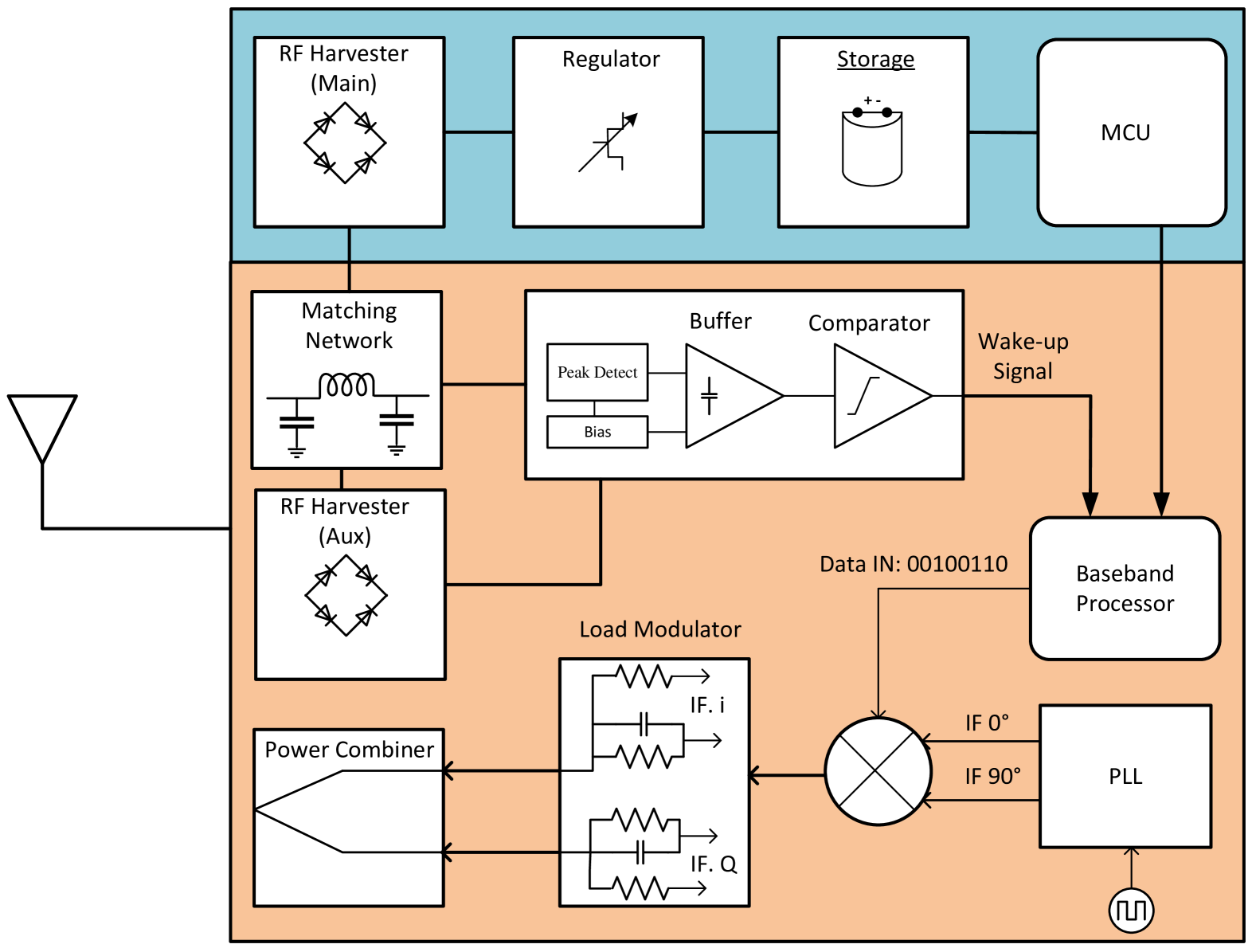
Advancing sub-10 GHz radio infrastructures that provide milliwatt-level power budgets will require novel EN device designs that can accommodate these substantial power budgets. A state-of-the-art strategy involves designing EN devices to operate with maximum efficiency at their device sensitivity, which is the minimum input power required for wake-up, thus maximizing their initial access distance. Traditionally, the power harvesting efficiency of the front-end degrades at higher input powers, posing a challenge for simultaneous efficient operation at both the device sensitivity and the maximum power budget. We propose a front-end design with two branches to address this challenge, as illustrated in Fig. 5. The lower branch is dedicated to solving the initial access problem, while the upper one is responsible for harvesting the maximum power from the focal region, once it is established. These branches have different requirements, leading to the development of two distinct harvesting strategies named main RF harvester (MRFH) and auxiliary RF harvester (ARFH), respectively. The ARFH must operate at very low sensitivities (e.g., down to , typical for RFID tags) with high conversion efficiency to provide sufficient energy for driving the wake-up signal processing, the baseband processor, and the modulator. Conversely, the MRFH must operate at high voltages (above ) to be able to properly deliver power levels up to to the storage device in order to efficiently drive power-consuming functions on the microcontroller unit (MCU). As a consequence, the ARFH is composed of stages of concatenated charge pumps [18], and the MRFH is fabricated as a single bridge rectifier using Schottky diodes to provide minimal forward voltage drop. These contradicting requirements prohibit the integration of both types of harvesters on a single die in a cost-effective way. The main contributing factors are the electrostatic discharge (ESD) protection, the maximum tolerable semiconductor process voltage (usually below ), and the utilization of specific transistor types w.r.t. efficiency versus operational voltage tolerance. Hence, the low-power (lower) branch is built as an integrated solution, while the high-power (upper) branch is located off-chip. Both branches are connected through a dedicated matching network and ESD protection to the antenna.
IV Challenges of Operating Energy-Neutral Devices
While batteryless EN devices constitute a key enabling technology for massive IoT deployments, the advantages bring along several challenges: One of them is the initial access problem that arises before the first successful wake-up and communication with an EN device. In that phase, measured CSI is unavailable and beamformers must resort to some form of predicted CSI or CSI-free methods. Another challenge is maintaining communication with EN devices in distributed architectures (e.g., RadioWeaves or Radio Stripes). The infrastructure splits resources between transmit and receive arrays, enabling half-duplex bistatic backscatter communication (BiBC) that relaxes hardware demands yet still requires direct link interference (DLI) suppression.
IV-A Initial Access Strategies
The operation of batteryless EN devices demands solving the initial access problem: When the infrastructure is put into operation for the first time, it needs to communicate with EN devices and simultaneously supply them with power wirelessly. As measured CSI is unavailable before the initial wake-up of an EN device, our geometry-based beamformers provide an attractive solution for the problem. Unfortunately, the position of an EN device cannot always be assumed known, which adds to the complexity of the initial access problem. To compensate for a possibly unknown position, a beam sweep can be conducted, i.e., a space of possible positions can be searched iteratively until the initial wake-up of the EN device. It should be noted, however, that geometry-based CSI prediction demands a known geometry (including the array layout) and also a phase-calibrated array, i.e., the phases at all antennas within one array need to be aligned. Other approaches like (exhaustive) codebook-based beamforming, or random beamforming do not demand geometric information or phase-calibrated arrays. Both belong to the class of CSI-free methods, which have been found beneficial for simultaneously powering a large number of distributed devices [19, 20]. The former can achieve good performance if iterated through an exhaustive codebook of beamforming weights, but may become prohibitive in massive MIMO applications due to the large codebook sizes involved. Once the devices become active, a pilot can be sent to enable positioning and reciprocity-based beamforming. Due to the favorably low EN device sensitivity (e.g., ; see Section III-B), the random beamforming becomes a valuable option for the initial access. By combining the energy-inefficient random-beamforming strategy with geometry or reciprocity-based methods, a “closed-loop” approach can be formulated to address the initial access problem without the need for time-consuming exhaustive beam sweeps. It is evident that there is a strong synergy between positioning, environmental awareness, and power transfer [13].
IV-B Direct Link Interference Suppression in Distributed Infrastructures
The scenario depicted in Fig. 1 shows the operation of only a single, physically large array, and in addition to WPT, the EN device can send its information by reflecting the incoming RF signal, corresponding to a monostatic backscatter communication (MoBC) system. In MoBC, the array operates both as a carrier emitter and a reader, and transmits an RF signal to the EN device. The EN device then modulates the received RF signal and sends it back to the array. In MoBC, the round-trip propagation loss degrades the power received at the array from a signal backscattered from the EN device. MoBC requires full-duplex technology at the reader, and algorithms for self-interference cancellation, which have a high implementation complexity. RFID is a typical example of an MoBC system, which includes special hardware designs to cancel self-interference.
A distributed radio infrastructure will involve multiple arrays operating as a jointly coherent physically large synthetic aperture. Distributed arrays allow for bistatic operation, resulting in a BiBC system. In BiBC, the arrays are spatially separated and each array works either as carrier emitter or reader – with each array operating in half-duplex mode. This makes the design much less complex than in a monostatic system. Furthermore, with BiBC the system can optimize which arrays act as carrier emitter and reader, depending on the location of the EN device.
However, BiBC suffers from DLI between the carrier emitter and the reader. In addition, the received power from the EN device is much weaker than the DLI, due to the double path-loss effect on the cascade backscatter channel. Therefore, in the presence of significant DLI, high-dynamic-range analog-to-digital converters, which are power-hungry devices in multiple-antenna technology, are required in the reader circuitry to detect the EN device signal. DLI suppression can be used to minimize the interference from carrier emitter to reader arrays. In [21], we proposed a transmission scheme for BiBC that suppresses DLI and reduces the required dynamic range, allowing the use of lower-resolution analog-to-digital converters. This transmission scheme includes direct link channel estimation, transmit beamformer design to cancel the DLI, and detection of the information from the EN device. We focused on DLI cancellation for transmission without prior information about the location of the EN device. Future work could include the design of schemes that beamform power towards an EN device whose location is known, while mitigating DLI.
The transmission scheme proposed in [21] can also be used for initial access. Prior to the initial access, the CSI and the position of the EN device are unknown, and it may not be possible to beamform power towards the EN device. In this case, one can combine the DLI cancellation technique of [21] with the initial access methods mentioned in Section IV-A to wake up the EN device and receive a pilot signal from it.
V Conclusions and Outlook
In this article, we have demonstrated how the physical aperture is a fundamental resource for achieving efficient and regulatory-compliant WPT in 6G wireless networks. Physically large apertures provide high WPT efficiency in the near-field focal region while maintaining low power densities outside, even in proximity to the infrastructure, reducing human exposure and improving regulatory compliance. They elevate power budgets into the milliwatt range when operating at sub-10 GHz frequencies, paving the way for a new generation of highly capable EN devices that can be deployed sustainably at a massive scale. At the same time, conjugate beamforming naturally exploits multipath propagation to increase the effective physical aperture size, which improves the WPT efficiency, narrows the focal region, and mitigates interference. While perfect CSI will leverage the maximum array gain, imperfect CSI will result in power losses. This may affect both reciprocity-based beamforming suffering from noisy CSI measurements, and geometry-based beamforming using CSI from a mismatched channel model. Among the future challenges resides the combination of both types of CSI in environment-aware radio infrastructures that promise ultra-reliable and efficient operation. A logical next step is the development of dedicated closed-loop optimization schemes. The efficiency of WPT systems is further limited by the accuracy and coherency of their clocks. Further exploration of the spatiotemporal synchronization of a distributed radio infrastructure will be required, ultimately transforming it into a single jointly coherent synthetic aperture that is massive both in the number of antennas and in physical size.
References
- [1] H. Rahmani, D. Shetty, M. Wagih, Y. Ghasempour, V. Palazzi, N. B. Carvalho, R. Correia, A. Costanzo, D. Vital, F. Alimenti, J. Kettle, D. Masotti, P. Mezzanotte, L. Roselli, and J. Grosinger, “Next-generation IoT devices: Sustainable eco-friendly manufacturing, energy harvesting, and wireless connectivity,” IEEE Journal of Microwaves, vol. 3, no. 1, pp. 237–255, 2023.
- [2] O. L. A. López, D. Kumar, R. D. Souza, P. Popovski, A. Tölli, and M. Latva-Aho, “Massive MIMO with Radio Stripes for indoor wireless energy transfer,” IEEE Transactions on Wireless Communications, vol. 21, no. 9, pp. 7088–7104, 2022.
- [3] B. Clerckx, K. Huang, L. R. Varshney, S. Ulukus, and M.-S. Alouini, “Wireless power transfer for future networks: Signal processing, machine learning, computing, and sensing,” IEEE Journal of Selected Topics in Signal Processing, vol. 15, no. 5, pp. 1060–1094, 2021.
- [4] E. Björnson, F. Kara, N. Kolomvakis, A. Kosasih, P. Ramezani, and M. B. Salman, “Enabling 6G performance in the upper mid-band by transitioning from massive to gigantic MIMO,” 2024. [Online]. Available: https://arxiv.org/abs/2407.05630
- [5] B. J. B. Deutschmann, T. Wilding, M. Graber, and K. Witrisal, “XL-MIMO channel modeling and prediction for wireless power transfer,” in 2023 IEEE International Conference on Communications Workshops (ICC Workshops), 2023, pp. 1355–1361.
- [6] T. L. Marzetta, E. G. Larsson, H. Yang, and H. Q. Ngo, Fundamentals of Massive MIMO. Cambridge University Press, 2016.
- [7] E. Björnson, O. T. Demir, and L. Sanguinetti, “A primer on near-field beamforming for arrays and reconfigurable intelligent surfaces,” in 2021 55th Asilomar Conference on Signals, Systems, and Computers, 2021, pp. 105–112.
- [8] A. Pizzo, A. Lozano, S. Rangan, and T. L. Marzetta, “Wide-aperture MIMO via reflection off a smooth surface,” IEEE Transactions on Wireless Communications, pp. 1–1, 2023.
- [9] REINDEER Project, “System design study for energy-neutral devices interacting with the RadioWeaves infrastructure,” Deliverable ICT-52-2020 / D4.1, Sep. 2023. [Online]. Available: https://doi.org/10.5281/zenodo.10548394
- [10] P. Ramezani, A. Kosasih, A. Irshad, and E. Björnson, “Exploiting the depth and angular domains for massive near-field spatial multiplexing,” IEEE BITS the Information Theory Magazine, pp. 1–12, 2023.
- [11] H. Zhang, N. Shlezinger, F. Guidi, D. Dardari, and Y. C. Eldar, “6G wireless communications: From far-field beam steering to near-field beam focusing,” IEEE Communications Magazine, vol. 61, no. 4, pp. 72–77, 2023.
- [12] European Council, “1999/519/EC: Council recommendation of 12 July 1999 on the limitation of exposure of the general public to electromagnetic fields (0 Hz to 300 GHz),” pp. 59–70, Jul. 1999. [Online]. Available: https://eur-lex.europa.eu/legal-content/EN/TXT/?uri=CELEX:31999H0519
- [13] B. J. B. Deutschmann, E. Leitinger, and K. Witrisal, “Geometry-based channel estimation, prediction, and fusion,” 2025, unpublished.
- [14] T. Wilding, B. J. B. Deutschmann, C. Nelson, X. Li, F. Tufvesson, and K. Witrisal, “Propagation modeling for physically large arrays: Measurements and multipath component visibility,” in 2023 Joint European Conference on Networks and Communications & 6G Summit (EuCNC/6G Summit), 2023, pp. 204–209.
- [15] REINDEER Project, “Initial assessment of architectures and hardware resources for a RadioWeaves infrastructure,” Deliverable ICT-52-2020 / D2.1, Jan 2022. [Online]. Available: https://doi.org/10.5281/zenodo.5938908
- [16] European Council, “2006-771-EC: Commission decision of 9 November 2006 on harmonisation of the radio spectrum for use by short-range devices,” pp. 66–70, Nov. 2006. [Online]. Available: https://eur-lex.europa.eu/legal-content/EN/TXT/PDF/?uri=CELEX:32006D0771(01)
- [17] REINDEER Project, “Use case-driven specifications and technical requirements and initial channel model,” Deliverable ICT-52-2020 / D1.1, Sep. 2021. [Online]. Available: https://doi.org/10.5281/zenodo.5561843
- [18] L. Zöscher, P. Herkess, J. Grosinger, U. Muehlmann, D. Amschl, and W. Bösch, “Passive differential UHF RFID front-ends in a 40 nm CMOS technology,” in 2017 47th European Microwave Conference (EuMC), 2017, pp. 105–108.
- [19] O. L. A. López, H. Alves, R. D. Souza, and S. Montejo-Sánchez, “Statistical analysis of multiple antenna strategies for wireless energy transfer,” IEEE Transactions on Communications, vol. 67, no. 10, pp. 7245–7262, 2019.
- [20] J. Van Mulders, B. Cox, B. J. B. Deutschmann, G. Callebaut, L. De Strycker, and L. Van der Perre, “Keeping energy-neutral devices operational: a coherent massive beamforming approach,” in 2024 IEEE 25th International Workshop on Signal Processing Advances in Wireless Communications (SPAWC), 2024, pp. 6–10.
- [21] A. Kaplan, J. Vieira, and E. G. Larsson, “Direct link interference suppression for bistatic backscatter communication in distributed MIMO,” IEEE Trans. Wireless Commun., vol. 23, no. 2, pp. 1024–1036, 2024.