Aerial Gym Simulator: A Framework for Highly Parallelized Simulation of Aerial Robots
Abstract
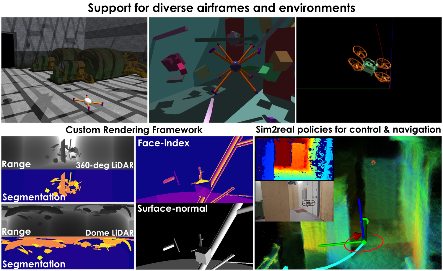
This paper contributes the Aerial Gym Simulator, a highly parallelized, modular framework for simulation and rendering of arbitrary multirotor platforms based on NVIDIA Isaac Gym. Aerial Gym supports the simulation of under-, fully- and over-actuated multirotors offering parallelized geometric controllers, alongside a custom GPU-accelerated rendering framework for ray-casting capable of capturing depth, segmentation and vertex-level annotations from the environment.
Multiple examples for key tasks, such as depth-based navigation through reinforcement learning are provided. The comprehensive set of tools developed within the framework makes it a powerful resource for research on learning for control, planning, and navigation using state information as well as exteroceptive sensor observations. Extensive simulation studies are conducted and successful sim2real transfer of trained policies is demonstrated. The Aerial Gym Simulator is open-sourced at:
https://github.com/ntnu-arl/aerial_gym_simulator.
Index Terms:
Aerial Systems: Perception and Autonomy, Machine Learning for Robot Control, Reinforcement Learning.I INTRODUCTION
With increasing deployment in a vast range of applications, including inspection, delivery, and search-and-rescue, aerial robots have gained immense popularity. Multirotor systems of varying scales have taken diverse roles and forms ranging from large vehicles with significant payload-carrying capacity to racing micro drones and reconfigurable robots capable of changing their shape actively or passively for traversal [1, 2, 3, 4] or manipulation [5, 6]. Critically, each unique robot configuration requires addressing embodiment- and task-specific challenges in terms of control, sensing capabilities, perception, and planning. With changes in the number of propellers, structural materials, overall platform size, payloads, the onboard sensor suite, as well as the environment within which a system is expected to operate, autonomy design and optimization need to exploit high-end simulation toward a safer and faster path to resilient deployment. This is even more critical when a) unconventional airframes are employed, such as novel multirotor configurations, reconfigurable multi-linked systems, or soft drones, as well as when b) learned exteroception-driven autonomous (e.g., depth cameras-based) navigation is concerned.
Accordingly, the field of aerial robotics shall greatly benefit from simulation tools that offer accurate physics models, parallelized rendering capabilities, out-of-the-box support for diverse airframes, and integration with established robot learning tools alongside ready-to-use control implementations. To address these issues, we contribute the Aerial Gym Simulator which builds upon NVIDIA Isaac Gym [7] and offers a feature-rich, modular, integrated, highly parallelized simulation and rendering framework that further incorporates explicit functionality for learning control and exteroceptive navigation policies as shown in Fig.˜1. In detail, our contributions include:
-
•
A highly-parallelized simulation framework for simulation of under-, fully-, and over-actuated multirotor platforms.
-
•
A comprehensive control suite and interfaces for arbitrary airframes across a wide range of abstraction levels ranging from position setpoints to RPM control with simulated motor dynamics.
-
•
A GPU-based rendering framework to create, maintain, and update parallel rendering environments that can be randomized separately and modified at runtime. Standalone kernels for parallelized ray-casting are developed to simulate custom sensor models.
-
•
Integration with Deep Reinforcement Learning (DRL) frameworks exploiting ready-to-use-controllers, accelerated rendering and their inter-compatibility with various airframes. Established frameworks [8, 9, 10] are integrated for seamless policy training. Extensive experimental studies are conducted to demonstrate the sim2real transferability of policies trained for state-based control and vision-based navigation tasks.
In the remainder of this paper, Section˜II presents related work, followed by the simulator description in Section˜III. Section˜IV provides benchmarks for physics and rendering throughput. Real-world and simulation experiments are detailed in Section˜V followed by conclusions in Section˜VI.
II RELATED WORK
High-fidelity simulators allow researchers to reliably test their algorithms in a safe, scalable, cost- and time-efficient manner. There has been immense progress in the field of aerial robot simulation with a wide number of simulators being used [11]. Several simulators respond to individual needs such as that of accurate dynamics (RotorS [12] and Hector Quadrotor [13]) by developing on top of universal simulators like Gazebo [14]. Other simulators such as FlightGoggles [15] and Flightmare [16] focus on photorealistic rendering and high-fidelity graphics using Unity [17], without simulating contact or collisions. AirSim [18], built over the Unreal Engine [19] simulates robot dynamics and collisions while offering high-fidelity rendering but typically requires large computational resources. Gym-pybullet-drones [20] developed over the PyBullet [21] physics engine, offers CPU-based simulation and rendering.
With the advent of Graphics Processing Unit (GPU)-accelerated physics and rendering engines, simulators and frameworks such as Isaac Gym [7], Orbit [22] and MuJoCo [23] are widely used to train policies for multi-linked legged systems and articulated robotic arms, often demonstrating impressive locomotion and manipulation capabilities [24, 25, 26, 27] with proprioceptive and exteroceptive inputs. Similar work related to control, planning, navigation and manipulation with multi-linked flying and soft systems [6, 2, 5, 28, 1] lacks available integration with simulation tools for ease of reliable replication and reproduction. Notably, OmniDrones [29] based on NVIDIA Isaac Sim provides support for the simulation of reconfigurable multirotor platforms based on motor commands but lacks support for control-allocation for non-planar airframes. While the native rendering functionality offered with Isaac Sim is slow, Warp based functionality allows for faster ray-casting against a single mesh that is shared across parallel environments and cannot be modified.
The proposed open-sourced simulation framework aims to bridge the gap by providing interfaces for highly parallelized simulation of aerial systems, closely integrated with a custom GPU-accelerated rendering framework. Providing interfaces that imitate real-world robot interfaces at various levels of control abstraction enables rapid development for policies using both proprioceptive and exteroceptive sensing modalities for control, navigation, and planning for arbitrary multirotor configurations. Moreover, a set of provided examples for training policies for depth-based autonomous navigation and control for arbitrary multirotor platforms allow users to jump-start their research in learning for multirotor platforms.
III FEATURES
Exploiting the physics engine and interfaces provided by NVIDIA Isaac Gym and developing on the advancements made in an earlier pre-release [30], this simulator represents a mature solution with a host of new features. A rich set of tools is provided that enables massively parallel simulation for aerial platforms, an integrated GPU-accelerated rendering framework to simulate custom sensor models and new sensing modalities with support for multirotor configurations with arbitrary motor numbers and locations. The simulator is redesigned, allowing each module to access the latest states and sensor data, leading to increased rendering throughput and overall simulation speed. A set of parallelized controllers at various control abstraction levels imitating real-world control interfaces are provided, alongside modeling of motor dynamics to bridge the sim2real gap. Additionally, linear and quadratic terms can be configured to simulate aerodynamic drag. Finally, the combined features of the simulator enable researchers to jump-start training policies for control, planning, and navigation for multirotor platforms with exteroceptive sensor measurements such as depth maps.
III-A Architecture
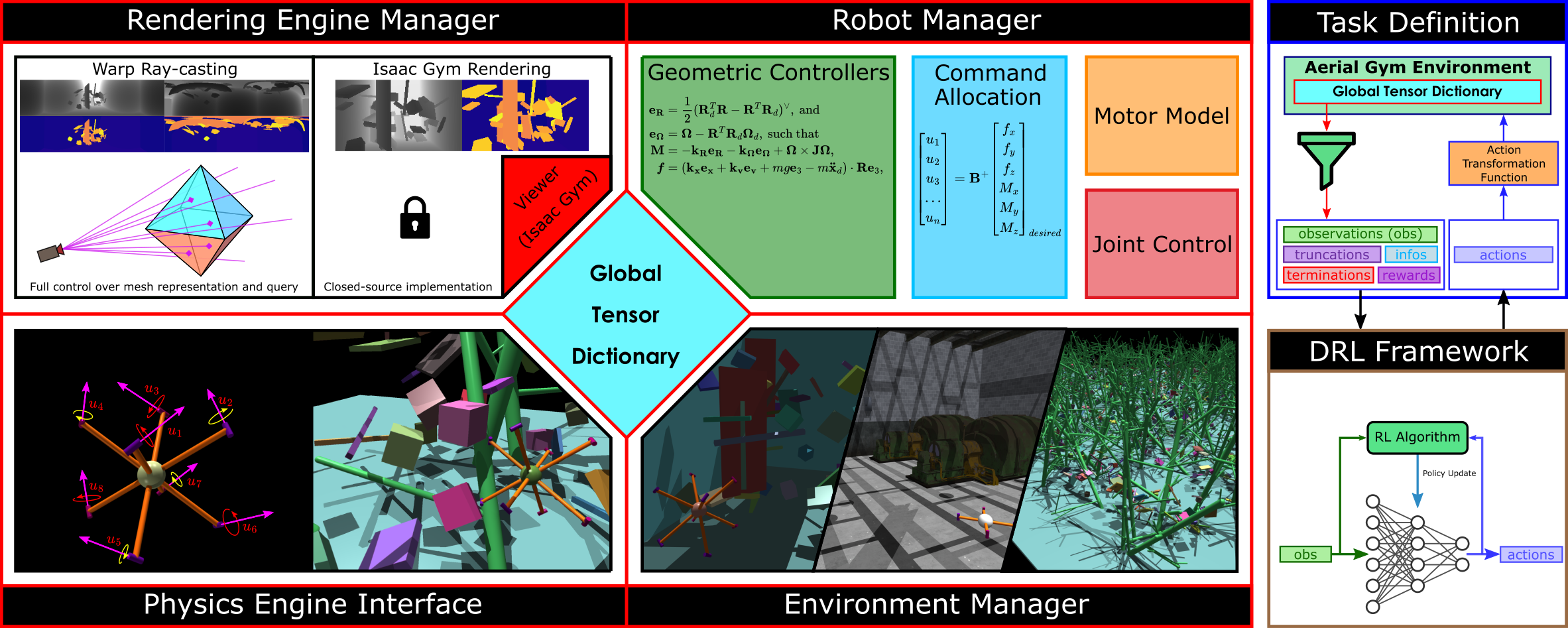
The simulator is designed to be modular with separate components for each functionality as shown in Fig.˜2. The major components of the Aerial Gym Simulator are the managers for the rendering engine, robots and environments, interfaces for the physics engine and common DRL frameworks along with the definition of learning tasks. All these components share a common memory bank dubbed as the Global Tensor Dictionary (GTD) and perform in-place operations on the tensors in GTD. The managers for rendering engine, robots and environments perform the substeps related to their domain. Aerial Gym obtains states and joint information of all simulated entities from the Isaac Gym physics engine and updates the GTD at each physics step. The geometric controllers use the robot states from the GTD and provide the forces and torques to be applied to the robot’s actuators. Task definitions are constructed conforming to the Gymnasium API [31] and provide task-specific interpretations of the information stored in the GTD. These are then provided as observations to an interfaced DRL framework for policy training.
III-B Multirotor Embodiments
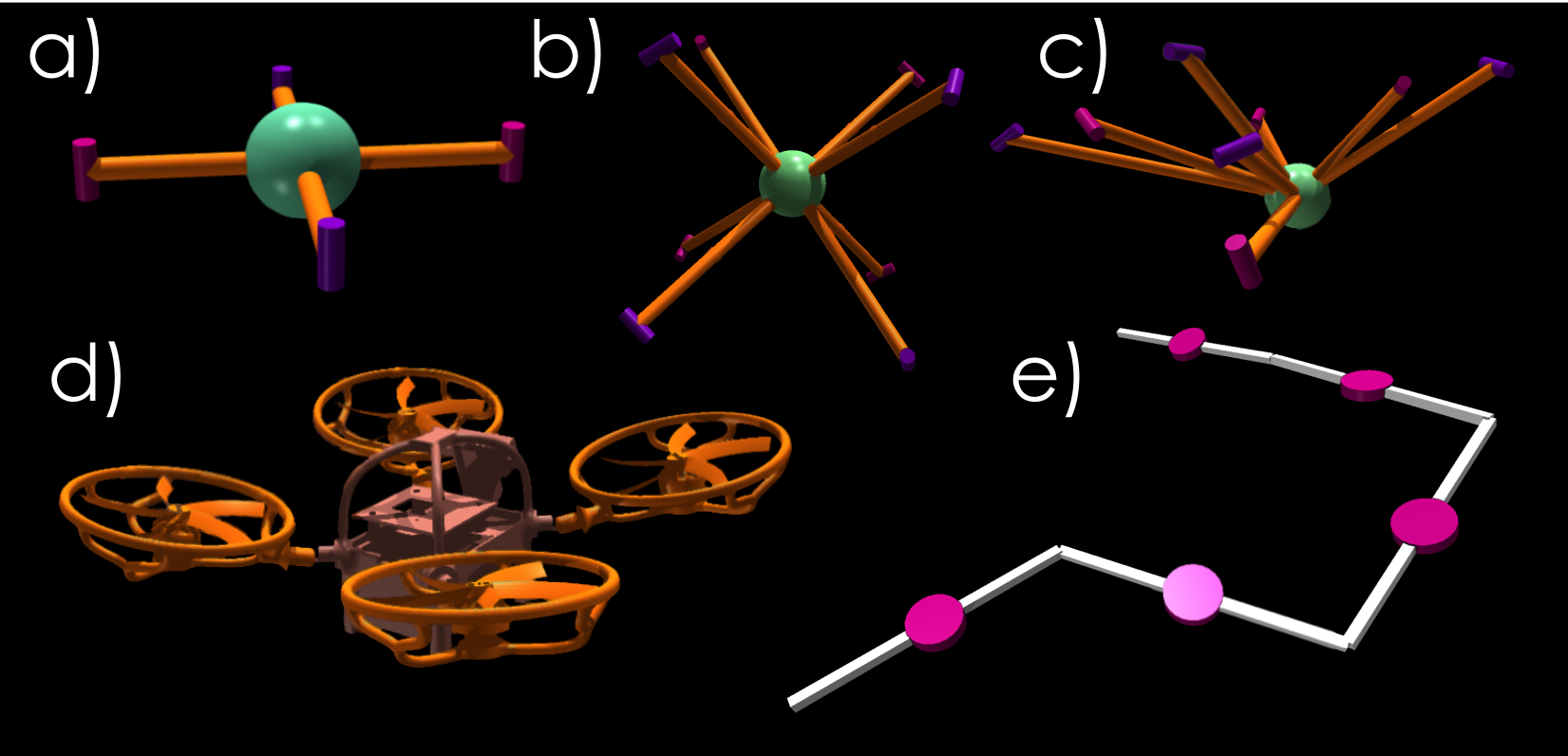
With renewed interest in task-specific embodiments, including non-planar airframes [32] and highly asymmetric multi-linked systems, that may further involve reconfigurability [5, 1, 6] and softness [28], there is a need for simulators that support such platforms. Responding to this need, the Aerial Gym Simulator is developed to support the simulation of various airframe configurations out-of-the-box. A user-specified configuration file for each robot platform defines the number of motors, joint parameters and the selected sensors for an embodiment defined with a Universal Robot Description Format (URDF) file. The simulator is also able to handle complex meshes and convex decompositions of non-convex meshes to simulate collisions with the environment albeit at a higher computation cost. Fig.˜3 shows example robot airframes provided with the simulator.
III-B1 Simulation for Arbitrary Rigid Configurations
Arbitrary -motor configurations can be simulated, with a robot configuration file specifying the number, relative poses, and directions of the motors. Robots are defined using URDF files as required by NVIDIA Isaac Gym.
III-B2 Flexible and Reconfigurable Airframes
Recent works investigate actively and passively morphing multirotors with flexible arms that change the robot morphology in flight [3, 1, 4]. The Aerial Gym Simulator supports simulation of such airframes with both active and passive rotational joints. Each joint can be interfaced with a PD-controller provided by Isaac Gym, or with a custom implementation matching the actuator or the compliant-response properties of real-world robots. Open-source examples include an accurate model of compliant joints of the Morphy platform [28], alongside a model for a reconfigurable multi-linked flying platform inspired by the work in [5] to accelerate relevant research efforts.
III-C Controllers and Interfaces
The simulator is equipped with various controllers across levels of abstraction based on the taxonomy in [33], intended to accelerate research efforts by exploiting commonly-used control interfaces with learning algorithms. Adapted geometric controllers based on [34] are provided, with sub-optimal performance on non-planar configurations serving as a starting point for future research. The provided controllers employ PyTorch’s JIT-compiled modules for faster execution on the GPU. Robots with any chosen level of control abstraction can be closely integrated with a DRL framework to train policies for control and navigation. The following controllers, interfaces are currently provided:
III-C1 Attitude-Thrust and Angular Rate-Thrust Controllers
The errors in desired orientation and body rates , alongside the resulting desired body-torque are computed as per [12] which is inspired by [34]:
| (1) | ||||
| (2) | ||||
| (3) |
where is the desired body-torque expressed in the body-fixed frame , and denote the current and desired orientation, and denote current and desired angular rates of the robot, all expressed in and being adequate weights. The robot moment of inertia is denoted as and the vee-map is denoted by . For attitude-thrust control, the desired angular velocity is set to , and for angular rate-thrust control . The total thrust command expressed in is directly provided to the control allocation scheme to obtain motor commands.
III-C2 Position, Velocity and Acceleration Controllers
The desired body-torque is calculated as in (3) and the thrust command is calculated as:
| (4) |
where and denote the position and velocity errors in the inertial frame , denote the respective weights, is the magnitude of acceleration due to gravity, is the robot mass, is the desired robot acceleration in , while is a unit vector in the z-direction. The matrix denoting desired orientation in this case is calculated as , where
| (5) |
and , such that , where denotes the desired yaw as per [12]. The -norm is denoted by . For the case of velocity control and , for acceleration control and . Similarly, for position control and .
III-C3 Body-wrench Controller
The desired or externally-commanded body-wrench is represented as . For an -rotor system, the thrust command provided to the actuators is . The embodiment-specific control-effectiveness matrix [35] relates and as:
| (6) | ||||
| (7) |
The Moore-Penrose inverse (pseudoinverse), represented as is used to obtain an unconstrained least-squares solution for the desired or commanded motor forces , given a desired wrench . This allocation scheme is suboptimal for systems with input constraints but is a common approximation that can be replaced with custom strategies.
III-C4 RPM and Thrust Setpoint Interfaces
The Aerial Gym Simulator provides functionalities to choose between the interface to command the motors via either thrust or RPM setpoints. The desired RPM at time for motor , is obtained by solving the equation , where is the reference thrust setpoint and is the thrust constant for motor . The continuous-time response of the motor is modeled as:
| (8) | ||||
| (9) |
The motor-time constant is and takes the value in case of slowing down or otherwise. The response can be simulated using both the RK4 and Euler methods for numerical integration. The applied force is and the applied torque is equal to , where is the torque coefficient, and is the direction of rotation.
III-D Sensors
In the following section, the simulated sensors provided by the Aerial Gym Simulator are described.
III-D1 Exteroceptive Sensors
NVIDIA Isaac Gym comes packaged with a rendering solution that has several limitations. Specifically, the users are restricted to only camera sensors using a pinhole projection model, while providing interfaces for RGB, depth, segmentation and optical flow information. The addition of data types and different projection models for sensors such as Time-of-Flight (ToF) cameras and -D LiDARs is not possible. Moreover, the loop-based access scheme for each sensor instance provided by Isaac Gym for pose randomization leads to slower simulation speeds. To overcome these limitations, we implement a custom rendering framework based on NVIDIA Warp [36] that complements the default rendering engine. For an environment , a base triangle-mesh representation containing sub-meshes is created as , where each sub-mesh corresponds to an individual object in simulation. Simultaneously, transformations for each sub-mesh at time are maintained as . The vertices of the mesh are transformed to match the obstacles in the simulator at time as , where the operator defines the transformation of each vertex of a sub-mesh with its corresponding transformation matrix for environment . Subsequently, a bounding volume hierarchy is calculated for for efficient ray-casting. While computationally expensive, performing this exclusively for randomization of static environments allows the Aerial Gym Simulator to effectively create, maintain and update multiple independent environments.
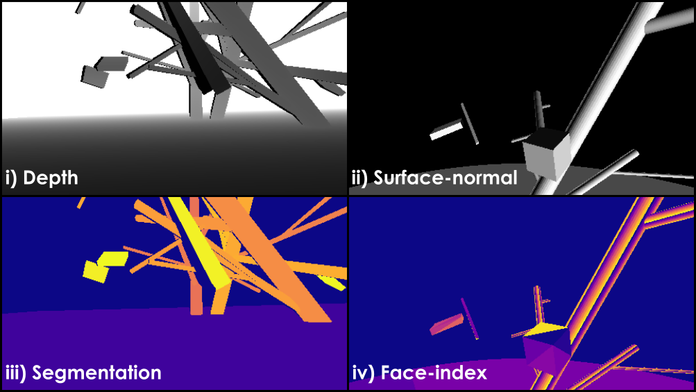
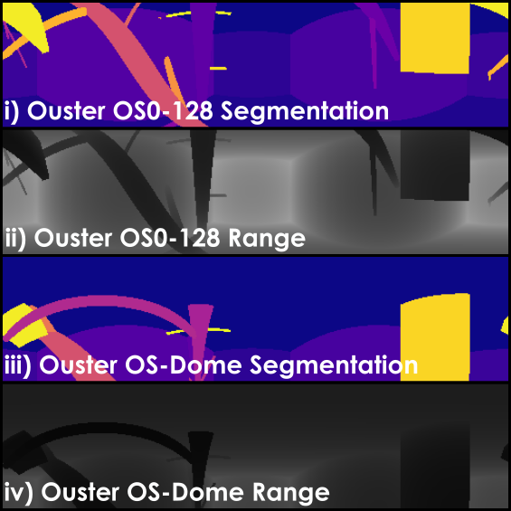
Standalone kernels for ray-casting are developed and integrated with the simulator. To obtain measurements, individual rays are cast outwards per-pixel to evaluate intersection with . The distance between the sensor and the point-of-intersection is reported as range for ToF sensors and LiDARs, while the distance of this point from the image plane is reported as depth. Shadows observed in stereo-camera systems are simulated by projecting rays back from the points-of-intersection towards the second sensor and marking pixels corresponding to the rays that intersect with the environment as invalid [37]. Additionally, it is also possible to embed vertex-level annotations that can be queried to obtain user-defined information from the environment. For example, vertex (or mesh-face) indices alongside barycentric coordinates of intersecting rays can be used to obtain user-specified information and infer gradients along the mesh surface as needed. Our realization of the GPU-accelerated ray-casting offers an order of magnitude speedup compared to the default rendering engine of Isaac Gym with support for newer data types such as point clouds and surface normals (Fig.˜4(a)). User-defined sensors with customizable projection models (e.g., Dome LiDAR Fig.˜4(b)) can be added. Moreover, the custom tensor-based implementation allows for consolidation of image tensors and faster randomization of sensor poses compared to Isaac Gym’s native loop-based API camera interface. For ease of use, we provide idealized configurations of: Ouster OS-0, OS-1, OS-2, OS-Dome, Intel RealSense D455, Luxonis Oak-D (and Pro W) and ST VL53L5CX ToF sensors.
III-D2 IMU Sensor
An IMU sensor model is implemented in the Aerial Gym Simulator to obtain proprioceptive measurements simulating real-world sensors. The simulated IMU utilizes the true forces measured by the simulator alongside a Gaussian noise and a discrete-time bias random-walk implementation as described in [38]. The measured acceleration and angular velocity about the sensor are calculated as:
| (10) | |||||
| (11) | |||||
| (12) | |||||
| (13) |
where , and is the true net force expressed in and is the angular rate experienced by the simulated robot at time expressed in , and are the biases and and are the noises for accelerometer and gyroscope sampled using a Gaussian distribution with standard deviations and respectively. and are the bias-drift terms while and are the standard deviations of the discrete-time random-walk model for the accelerometer and gyroscope respectively. The simulated IMU orientation can be randomized with the measurements appropriately transformed. Noise density and bias random-walk configurations are measured and provided for the VectorNav VN-100 and Bosch BMI085 IMUs.
III-E Learning-based Control and Navigation
Deep neural networks have shown great promise in tackling the challenge of state-based control [33, 24, 39]. However, effective training with high-dimensional exteroceptive sensor data remains a pertinent challenge. In view of accelerating this effort, we integrate established learning frameworks such as RL Games [8], Sample Factory [9] and Clean RL [10] with Aerial Gym. Interfaces are provided to train policies for multirotor control and exteroceptive sensor-based navigation. Environments conforming to the Gymnasium standard [31] are provided for control and navigation tasks for aerial platforms at varying levels of control abstraction. To deliver ready-to-use tools and examples we a) package environments for DRL-based control of arbitrary multirotor platforms for position-setpoint tracking with deep neural networks interfaced to command robots at the chosen control-abstraction level, b) exploit the integrated rendering framework offering exteroceptive sensor data to train DRL policies for map-free navigation and c) demonstrate through experimental evaluations robust sim2real transfer of policies trained using the simulator. Results from experimental validations are shown in Section˜V.
IV BENCHMARKING
| Physics (SPS) | Rendering (FPS) | Sensors | ||||||||||
| Instances / Features | RGB-D(Seg) | LiDAR | IMU | Face/Normal | ||||||||
| gym-pybullet-drones [20] | ✗ | ✗ | ✗ | ✓ | ✗ | ✗ | ✗ | |||||
| L2F [33]∗ | ✗ | ✗ | ✗ | ✗ | ✗ | ✗ | ✗ | ✗ | ||||
| OmniDrones [29] (Native) | ✗ | ✗ | ✓ | ✗ | ✗ | ✗/✓ | ||||||
| OmniDrones [29] (Warp) | ✗ | ✗ | ✓ | ✗ | ✗ | |||||||
| Aerial Gym Simulator | ✓ | ✓ | ✓ | ✓ | ||||||||
Benchmarking studies are performed against relevant open-source simulators that support the simulation of multiple multirotor platforms with either CPU or GPU-based simulation and rendering. We benchmark and compare the physics simulation speeds and rendering throughput of the Aerial Gym Simulator against gym-pybullet-drones [20], OmniDrones [29], and the simulator in Learning to Fly in Seconds (L2F) [33]. The comparison is performed by commanding constant RPM setpoints to quadrotors in obstacle-free environments for all simulators. Similarly, rendering performance is measured for the simulators in similar environments consisting of cube obstacles in front of the robots. A single camera with a resolution of pixels is simulated per robot capturing both depth and segmentation images. A workstation with an AMD Ryzen Threadripper Pro 3975WX CPU and NVIDIA RTX 3090 GPU is used for comparisons. The results for physics throughput in samples per second (SPS) and rendering throughput in frames per second (FPS) are tabulated in Table˜I alongside the provided rendering capabilities. An unsupported feature or absence of data due to simulator crash is indicated by ✗, while indicates values reported by the authors of L2F (using a laptop GPU).
| Sensor Resolution | Rendering Speed (FPS) | ||||
| Num. Envs. | 128 | 256 | 512 | 1024 | 2048 |
| Aerial Gym Simulator | |||||
| Isaac Gym | |||||
| ✗ | |||||
| ✗ | ✗ | ||||
Since gym-pybullet-drones [20] simulates quadrotors in a single environment, the simulated cameras observe other robot meshes slowing down rendering. For OmniDrones [29], the comparison is made against the performance using both the native cameras and the NVIDIA Warp-based ray-casting functionality provided by Isaac Lab. Notably, the ray-casting functionality can only work with a single static mesh shared across environments and does not allow modifying the mesh once initialized, whereas Aerial Gym Simulator allows modifications to each individual environment mesh at runtime. Therefore the benchmarking is done with a heightmap provided in the respective repository. L2F [33] simulates rigid multirotors providing a large speedup compared to other simulators, but does not consider interactions with other objects and does not offer any rendering capabilities. In contrast, our implementation not only allows for highly-parallelized simulation of arbitrary multirotor systems but also provides a powerful rendering implementation that allows maintaining and updating individual meshes per environment, offering significantly greater control over the randomization of the environments.
We also compare the proposed rendering framework against Isaac Gym’s native rendering framework for depth and segmentation images in a room-like static environment consisting of floating obstacles. The rendering operations are performed with controller-in-the-loop (to emulate practical use-cases). The rendering throughput is measured for parallel environments and tabulated in Table˜II. The Aerial Gym Simulator offers an order of magnitude speedup over Isaac Gym for higher numbers of parallel environments but scales worse with resolution. Interestingly, Isaac Gym maintains similar throughput for higher-resolution cameras across the range of parallel environments, but requires significantly more GPU memory and crashes for a higher number of environments as indicated by ✗ in Table˜II.
V Experimental Evaluation
We evaluate the performance of the proposed simulator for training policies for various levels of control abstraction and sensor configurations. We use the RL Games framework [8] to train policies for high-level control tasks and simultaneously use Sample Factory [9] to train policies for both low-level control and vision-based navigation tasks across different robot platforms. The robot inertias are obtained using CAD, while the response of the simulated controllers and motor models is matched with that of the real-world system. The trained policies are directly deployed on real-world robots without additional fine-tuning to evaluate their performance. All evaluations presented are instances of open-sourced examples integrated with the Aerial Gym Simulator.
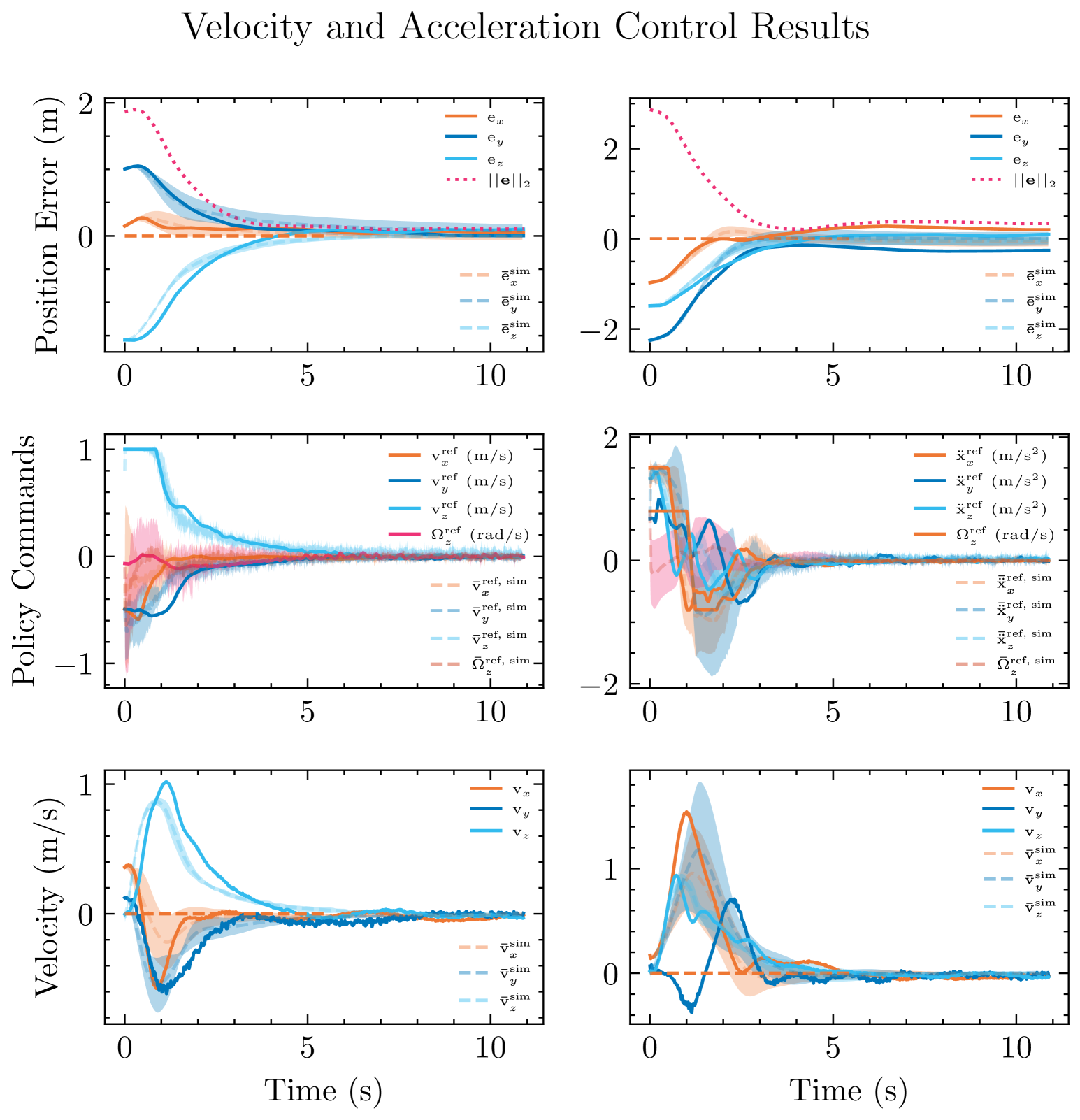
V-A Position-Setpoint Tracking Task
We train state-based DRL policies to control the position of a quadrotor by commanding it -D velocity and acceleration commands, alongside yaw rate commands. The platform similar to [40] is used, with ArduPilot firmware and onboard odometry estimation based on ROVIO [41] using an Intel RealSense Depth Camera D455. The problem is formulated as a Markov Decision Process where the state of the robot at time is defined as , with being the -D position-error expressed in and representing the orientation of the robot, and are the linear and angular velocities of the robot expressed in . We use as subscripts denoting the values for the respective axes. is the commanded action to the robot in the previous time-step. The action at time is defined as for velocity-control task and for acceleration-control task, where , and are the -D velocity, -D acceleration and yaw rate commands respectively, expressed in the vehicle-frame . Fig.˜5 shows the real-world performance of the policies.
V-B Vision-based Navigation Task
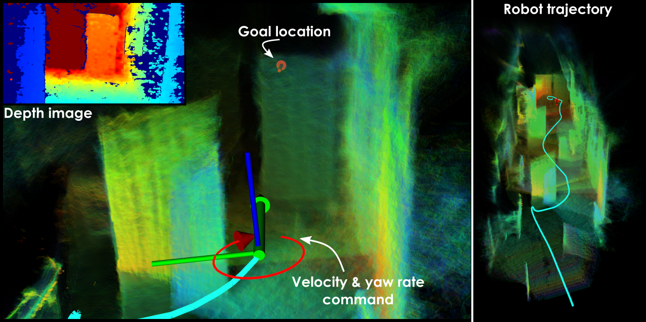
Demonstrating the applicability of our simulator for sim2real transfer for tasks involving high-dimensional and noisy depth data, we train a policy for fast, map-free navigation of cluttered environments. We define the problem similar to the work in [40], and train a policy with the latent space from the Deep Collision Encoder (DCE) [42]. The state is defined as , where represents expressed in , and represent robot roll and pitch angles, while is a transformation to obtain velocity and yaw rate commands, identical to the transformation in [40]. is a -dimensional representation obtained from a resolution depth image using the DCE. The policy is trained for a wall-clock time of . During real-world testing using the above platform, we constrain the vertical velocity commanded by the network to discourage the robot from going over the obstacles. Instances of policy commands along with robot path are visualized in Fig.˜6. With a maximum and mean speeds of and respectively, the robot navigates the cluttered corridor despite significant noise in the depth image.
V-C Motor Control for Position-Setpoint Tracking Task
We use a different planar quadrotor platform equipped with the ModalAI Voxl 2 Mini board and ModalAI Voxl ESC. A Qualisys Motion Capture system is used to estimate the pose of the robot. A fully-connected neural network consisting of -layers with and neurons is trained using Sample Factory [9] for different seeds. The network is deployed on the compute board in a custom PX4 module using Eigen and C++. The state is defined as , where denotes the position error expressed in , while denotes the 6-D rotation representation based on [43]. The network commands motor thrust setpoints . These are converted to RPM setpoints using identical thrust constants and commanded to the motors. We deploy all policies to evaluate and compare their performance. Figure 7 shows the mean and standard deviation of measurements across experiments.
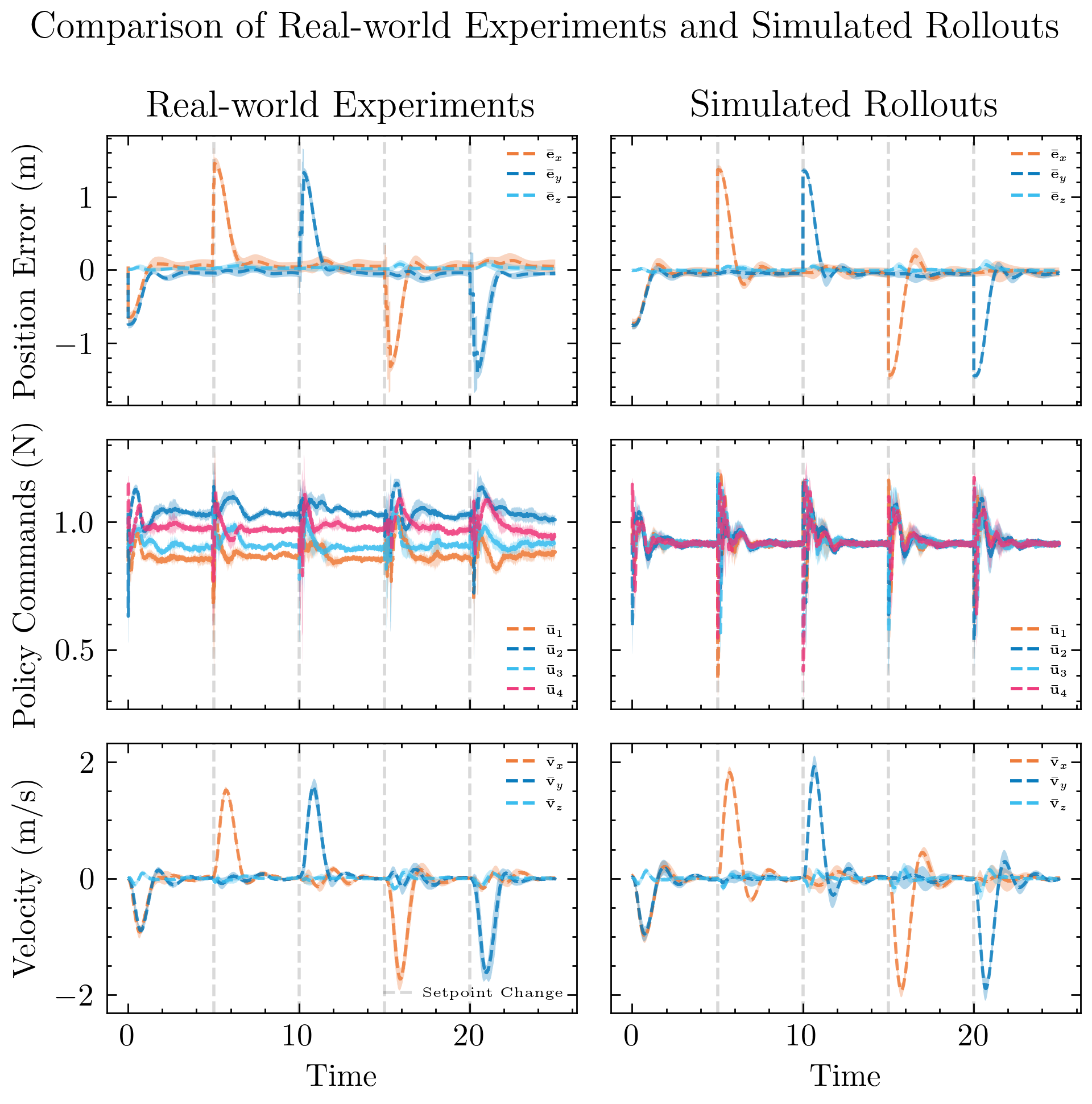
The networks are trained with a control time-step duration of in simulation. Inference is performed at . The real-world performance matches the simulated rollouts with high-repeatability, with the average position tracking error across seeds . The policy commands in the simulated experiment converge to the same value for all motors, while the real-world thrust commands differ across motors. This might occur due to asymmetric mass distribution on the real-world platform leading to unmodeled torque or due to varying motor constants for different motors. Nevertheless, we achieve stable real-world tracking performance demonstrating the robustness enabled by the simulation framework.
VI CONCLUSIONS
This paper presented the Aerial Gym Simulator, an integrated simulation and rendering framework for multirotor platforms. Aerial Gym introduces functionality to support simulation and control of airframes with an arbitrary number of motors. A custom rendering framework is developed for accelerated ray-casting, exploits custom sensor models and supports parallelization across unique environment instances and offers an order of magnitude speedup compared to Isaac Gym. Extensive studies are conducted to demonstrate the robustness and sim2real transferability of state-based control and vision-based navigation policies. The simulator is open-sourced at:
https://github.com/ntnu-arl/aerial_gym_simulator
.
References
- [1] M. Zhao et al., “Design, modeling, and control of an aerial robot dragon: A dual-rotor-embedded multilink robot with the ability of multi-degree-of-freedom aerial transformation,” IEEE Robotics and Automation Letters, 2018.
- [2] M. Kulkarni, H. Nguyen, and K. Alexis, “The reconfigurable aerial robotic chain: Shape and motion planning,” IFAC-PapersOnLine, 2020.
- [3] D. Falanga, K. Kleber, S. Mintchev, D. Floreano, and D. Scaramuzza, “The foldable drone: A morphing quadrotor that can squeeze and fly,” IEEE Robotics and Automation Letters, 2019.
- [4] N. Bucki and M. W. Mueller, “Design and control of a passively morphing quadcopter,” in 2019 International Conference on Robotics and Automation (ICRA). IEEE, 2019, pp. 9116–9122.
- [5] M. Zhao, K. Kawasaki, X. Chen, S. Noda, K. Okada, and M. Inaba, “Whole-body aerial manipulation by transformable multirotor with two-dimensional multilinks,” in 2017 IEEE International Conference on Robotics and Automation (ICRA). IEEE, 2017, pp. 5175–5182.
- [6] H. Nguyen, T. Dang, and K. Alexis, “The reconfigurable aerial robotic chain: Modeling and control,” in 2020 IEEE International Conference on Robotics and Automation (ICRA), 2020, pp. 5328–5334.
- [7] V. Makoviychuk et al., “Isaac gym: High performance gpu-based physics simulation for robot learning,” 2021.
- [8] D. Makoviichuk and V. Makoviychuk, “rl-games: A high-performance framework for reinforcement learning,” https://github.com/Denys88/rl_games, May 2021.
- [9] A. Petrenko, Z. Huang, T. Kumar, G. Sukhatme, and V. Koltun, “Sample factory: Egocentric 3d control from pixels at 100000 fps with asynchronous reinforcement learning,” 2020.
- [10] S. Huang, R. F. J. Dossa, C. Ye, J. Braga, D. Chakraborty, K. Mehta, and J. G. Araújo, “Cleanrl: High-quality single-file implementations of deep reinforcement learning algorithms,” Journal of Machine Learning Research, 2022.
- [11] C. A. Dimmig, G. Silano, K. McGuire, C. Gabellieri, W. Hönig, J. Moore, and M. Kobilarov, “Survey of simulators for aerial robots: An overview and in-depth systematic comparisons,” IEEE Robotics & Automation Magazine, 2024.
- [12] F. Furrer, M. Burri, M. Achtelik, and R. Siegwart, “Rotors-a modular gazebo mav simulator framework,” in Robot Operating System (ROS). Springer International Publishing, 2016.
- [13] J. Meyer, A. Sendobry, S. Kohlbrecher, U. Klingauf, and O. von Stryk, “Comprehensive simulation of quadrotor uavs using ros and gazebo,” in Simulation, Modeling, and Programming for Autonomous Robots. Springer Berlin Heidelberg, 2012.
- [14] N. Koenig and A. Howard, “Design and use paradigms for gazebo, an open-source multi-robot simulator,” in 2004 IEEE/RSJ International Conference on Intelligent Robots and Systems (IROS) (IEEE Cat. No.04CH37566), 2004.
- [15] W. Guerra, E. Tal, V. Murali, G. Ryou, and S. Karaman, “Flightgoggles: Photorealistic sensor simulation for perception-driven robotics using photogrammetry and virtual reality,” 2019.
- [16] Y. Song, S. Naji, E. Kaufmann, A. Loquercio, and D. Scaramuzza, “Flightmare: A flexible quadrotor simulator,” in 4th Conference on Robot Learning (CoRL), 2020, pp. 1147–1157.
- [17] J. K. Haas, “A history of the unity game engine,” 2014.
- [18] S. Shah, D. Dey, C. Lovett, and A. Kapoor, “Airsim: High-fidelity visual and physical simulation for autonomous vehicles,” in Field and Service Robotics. Springer International Publishing, 2018.
- [19] Epic Games, “Unreal engine.” [Online]. Available: https://www.unrealengine.com
- [20] J. Panerati, H. Zheng, S. Zhou, J. Xu, A. Prorok, and A. P. Schoellig, “Learning to fly—a gym environment with pybullet physics for reinforcement learning of multi-agent quadcopter control,” in 2021 IEEE/RSJ International Conference on Intelligent Robots and Systems (IROS), 2021.
- [21] E. Coumans and Y. Bai, “2019. pybullet, a python module for physics simulation for games, robotics and machine learning,” 2016.
- [22] M. Mittal et al., “Orbit: A unified simulation framework for interactive robot learning environments,” IEEE Robotics and Automation Letters, vol. 8, no. 6, pp. 3740–3747, 2023.
- [23] E. Todorov, T. Erez, and Y. Tassa, “Mujoco: A physics engine for model-based control,” in 2012 IEEE/RSJ International Conference on Intelligent Robots and Systems. IEEE, 2012.
- [24] N. Rudin, D. Hoeller, P. Reist, and M. Hutter, “Learning to walk in minutes using massively parallel deep reinforcement learning,” in Conference on Robot Learning. PMLR, 2022, pp. 91–100.
- [25] D. Hoeller, N. Rudin, D. Sako, and M. Hutter, “Anymal parkour: Learning agile navigation for quadrupedal robots,” Science Robotics, 2024.
- [26] H. Huang, A. Loquercio, A. Kumar, N. Thakkar, K. Goldberg, and J. Malik, “Manipulator as a tail: Promoting dynamic stability for legged locomotion,” in 2024 IEEE International Conference on Robotics and Automation (ICRA), 2024, pp. 9712–9719.
- [27] Y. Narang, K. Storey, I. Akinola, M. Macklin, P. Reist, L. Wawrzyniak, Y. Guo, A. Moravanszky, G. State, M. Lu, A. Handa, and D. Fox, “Factory: Fast Contact for Robotic Assembly,” in Proceedings of Robotics: Science and Systems, New York City, NY, USA, June 2022.
- [28] P. De Petris, M. Nissov, and K. Alexis, “Morphy: A compliant and morphologically aware flying robot,” Advanced Intelligent Systems.
- [29] B. Xu, F. Gao, C. Yu, R. Zhang, Y. Wu, and Y. Wang, “Omnidrones: An efficient and flexible platform for reinforcement learning in drone control,” IEEE Robotics and Automation Letters, vol. 9, no. 3, pp. 2838–2844, 2024.
- [30] M. Kulkarni, T. J. L. Forgaard, and K. Alexis, “Aerial gym – isaac gym simulator for aerial robots,” 2023.
- [31] A. Kwiatkowski et al., “Gymnasium: A standard interface for reinforcement learning environments,” 2024.
- [32] D. Brescianini and R. D’Andrea, “Design, modeling and control of an omni-directional aerial vehicle,” in 2016 IEEE International Conference on Robotics and Automation (ICRA), 2016, pp. 3261–3266.
- [33] J. Eschmann, D. Albani, and G. Loianno, “Learning to fly in seconds,” IEEE Robotics and Automation Letters, 2024.
- [34] T. Lee, M. Leok, and N. H. McClamroch, “Control of complex maneuvers for a quadrotor uav using geometric methods on se(3),” 2011.
- [35] T. A. Johansen and T. I. Fossen, “Control allocation—a survey,” Automatica, vol. 49, no. 5, pp. 1087–1103, 2013.
- [36] M. Macklin, “Warp: A high-performance python framework for gpu simulation and graphics,” https://github.com/nvidia/warp, March 2022.
- [37] D. Scharstein and R. Szeliski, “A taxonomy and evaluation of dense two-frame stereo correspondence algorithms,” International journal of computer vision, vol. 47, pp. 7–42, 2002.
- [38] J. Rehder, J. Nikolic, T. Schneider, T. Hinzmann, and R. Siegwart, “Extending kalibr: Calibrating the extrinsics of multiple imus and of individual axes,” in 2016 IEEE International Conference on Robotics and Automation (ICRA), 2016, pp. 4304–4311.
- [39] E. Kaufmann, L. Bauersfeld, A. Loquercio, M. Müller, V. Koltun, and D. Scaramuzza, “Champion-level drone racing using deep reinforcement learning,” Nature, vol. 620, no. 7976, pp. 982–987, 2023.
- [40] M. Kulkarni and K. Alexis, “Reinforcement learning for collision-free flight exploiting deep collision encoding,” in 2024 IEEE International Conference on Robotics and Automation (ICRA), 2024, pp. 15 781–15 788.
- [41] M. Bloesch, S. Omari, M. Hutter, and R. Siegwart, “Robust visual inertial odometry using a direct ekf-based approach,” in 2015 IEEE/RSJ international conference on intelligent robots and systems (IROS). IEEE, 2015, pp. 298–304.
- [42] M. Kulkarni and K. Alexis, “Task-driven compression for collision encoding based on depth images,” in Advances in Visual Computing. Cham: Springer Nature Switzerland, 2023, pp. 259–273.
- [43] Y. Zhou, C. Barnes, J. Lu, J. Yang, and H. Li, “On the continuity of rotation representations in neural networks,” in Proceedings of the IEEE/CVF conference on computer vision and pattern recognition, 2019, pp. 5745–5753.