Superconducting Cloud Chamber
Abstract
We propose a new particle-trajectory detector composed of Josephson junctions, named the superconducting cloud chamber. By measuring the quantum phase difference, this device can detect charged particles with extremely low kinetic energy, providing a new method for detecting slow-moving particles. It can also be utilized to detect millicharged dark matter particles thermalized with the Earth’s environment within the mass range of GeV.
Introduction – Millicharged particles can be an interesting dark matter (DM) candidate Holdom:1985ag ; Feldman:2007wj ; McDermott:2010pa ; Izaguirre:2015eya ; Agrawal:2016quu because millicharge naturally ensures the stability of particle. As long as the millicharge of DM is large enough, it can reach thermal equilibrium with the Earth environment through long-range electromagnetic interactions with standard model (SM) particles Neufeld:2018slx ; Pospelov:2020ktu ; Leane:2022hkk ; Berlin:2023zpn . Consequently, the kinetic energy of DM becomes as tiny as the Earth’s temperature (eV), which prevents it from surpassing the energy threshold of DM direct detection experiments and thus evading experimental constraints Pospelov:2020ktu ; Berlin:2023zpn . Additionally, such a strong-interacting millicharged DM is thermally produced in the early Universe with a small abundance Aboubrahim:2021ohe . The cosmological observations are not sensitive to the DM with a small fraction Dubovsky:2003yn ; dePutter:2018xte ; Kovetz:2018zan ; Buen-Abad:2021mvc .
Although many new experiments are proposed to detect millicharged DMs Pospelov:2020ktu ; Kim:2007zzs ; Moore:2014yba ; Afek:2020lek ; Budker:2021quh , there are still many parameter spaces with large mass and small fraction for the millicharged DM that need exploration Budker:2021quh . Moreover, current particle detectors are unable to directly observe extremely low-velocity particles, even those SM charged particles, without acceleration. In this paper, we design a novel superconducting cloud chamber made of RF SQUIDs (radio frequency superconducting quantum interference device 34120 ) to target low-speed charged particles. We use natural units with throughout the text.
Phase Difference Induced from Charged Particles – A Josephson junction (JJ) consists of two superconductors with an insulating barrier in between. The electrons inside superconductors form Cooper pairs and become coherent states once the temperature is below the critical temperature. These two superconducting states on the different sides of the insulator, and , can be described by macroscopic wave functions, Landau:1950lwq . A tunneling current occurs when there is a phase difference between the two states, . This is the so-called Josephson effect Josephson:1962zz ; Josephson:1974uf . The Josephson current exhibits periodic dependence on phase, where is the constant critical current.
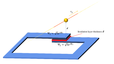
If the quantum states on each side of the insulator feel a voltage difference111Voltage can also be replaced by any interaction potential involving electrons, such as gravitational potential Jain:1987zz ; Ummarino:2020loo ; Christodoulou:2023hyt ; Cheng:2024zde and the fifth-force potential Cheng:2024yrn . , their phase difference can evolve over time according to the Schrodinger equation as . The factor of 2 arises from the fact that a Cooper pair consists of two electrons. A charged particle passing by a JJ can induce a potential and phase difference across the junction. As shown in Fig. 1, an unknown charged particle flies past the junction at a distance of with a velocity . Assuming the particle carries a charge , there exists a distance-dependent potential around it, with a magnitude of . Due to the thickness of the insulator in JJ, there is a distance difference of between the superconductors on either side of the insulating layer and the charged particle. Since the electric field is shielded inside superconductors, a voltage difference only exists across the junction. This voltage is also a function of time because of the motion of charged particle. The accumulated phase difference is the integration over the entire time domain as,
| (1) |
The thickness of the insulating layer is typically nm, which is tiny compared to the overall size of a JJ (m) and the distance (which is mm as explained in the section after the next). With , the above integration can be calculated analytically,
| (2) |
Although the integration in Eq. (1) is performed from to , the dominant contribution to the signal occurs when moves to a horizontal distance from the JJ that is less than (shown as the red dashed line in Fig. 1). During this distance, the travel time of is . Consequently, the flying charged particle induces a pulsed signal with frequency .
RF SQUID as Particle Detector – To detect the randomly occurring phase difference, we utilize the fact that a JJ behaves as a nonlinear inductance. The Josephson inductance, , is a function of the phase difference across the junction, where and . This expression holds true as long as the variation in the phase difference, , is small around the equilibrium value . Due to the perturbation from passing charged particles, a small phase difference develops across the junction, inducing a change in the Josephson inductance. The change in inductance can be detected by embedding the JJ into a superconducting loop with loop inductance , forming an RF-SQUID (the blue circuit in Fig. 1). We choose to ensure a non-hysteretic RF-SQUID.
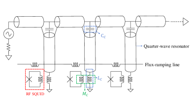
The general configuration and detectability of the chamber can be realized by a proposed microwave readout schema shown in Fig. 2. It was originally developed for large transition edge sensor (TES) arrays designed for cosmic microwave background observation and high-resolution X-ray/Gamma-ray spectrometers, where an RF-SQUID coupled to a TES pixel acts as a nonlinear flux-actuated inductor 2021ApPhL.118f2601D ; 6994798 ; 256711 ; 2017ApPhL.111f2601M ; HOLMES:2019ykt ; lens.org/027-935-516-419-894 ; SathyanarayanaRao:2020itw . In our proposal, charged particles directly interact with the JJ in the RF-SQUID, inducing a phase variation across the junction and altering its inductance. This results in a measurable resonance frequency shift of the quarter-wave resonators from to . In the small signal limit, the shift is Wegner:2021yrn ,
| (3) |
Here, is the first mode resonance frequency of the unloaded resonator and is its characteristic impedance. By measuring the resonance frequency shift, the phase variation induced by the charged particles can be deduced via the flux ramp modulation technique. Details are provided in Appendix A.
Sensitivity – The resolution of the phase variation induced by the passing charged particles is determined by the flux noise of the readout module. Since the RF-SQUID used here is dissipationless and there is no input filter, not like in the readout setup for TES arrays, the primary noise contributions are from: (1) noise of the RF-SQUID, (2) Johnson noise of the microwave amplifier, (3) two-level system (TLS) noise of the quarter-wave resonator, and (4) other energy loss factors in the readout circuit. State-of-the-art readout modules have achieved a system noise of less than 2020ApPhL.117l2601N ; Malnou:2023wfo . Additionally, low-frequency noise is further suppressed by the flux ramp modulation technique.
In conclusion, within the frequency range from 1 Hz to MHz, the detector exhibits its optimal readout sensitivity articlemates . This means that the detector is only sensitive to particles with velocities in the range of ). In our setup, the spacing mm and thus the corresponding detectable particle velocity is quite small as, .
To compare with the sensitivity of the experiment, we need to convert the phase difference caused by the charged particle into an equivalent magnetic flux. When a phase difference in an RF SQUID results in a Josephson current, due to geometrical self-inductance , a magnetic flux will also be generated within the loop. The relationship between phase difference and the perturbative magnetic flux is, , and thus gross2016applied ,
| (4) |
This magnetic flux can be understood from the following physical picture. The superconductors on both sides of the insulator are connected, so in the absence of an external field, their phases should be the same, . However, due to perturbation caused by the passing charged particles, a phase difference and Josephson current are induced across the junction. This current generates a magnetic flux through the self-inductance. The magnetic flux in the closed loop, in turn, produces an opposite phase difference, which offsets the phase difference induced by charged particles to maintain the aforementioned relationship222Notice that the magnetic field of the low-speed particle is a secondary effect compared to its electric field. The magnetic flux is actually induced by the electric field of passing charged particles and the self-inductance of RF SQUID.. Therefore, the criterion for the signal to be observable is that it must be greater than the experimental sensitivity, .
Superconducting Cloud Chamber – Based on the particle-detector unit made of an RF SQUID in Fig. 1 and the readout schema in Fig. 2, we propose a superconducting cloud chamber consisting of a 3D array formed by these units for visualizing the trajectories of charged particles. As shown in Fig. 3, each cube represents an RF SQUID shown in Fig. 1, and the distance between each detection unit in all three directions is . Typically, the size of an RF SQUID is m. We can design the spacing in the array to be times larger than the size of a single unit, such as mm. In this way, if a particle passes through the cloud chamber, its distance from the closest SQUIDs will be fixed roughly as mm.
For example, to create a cube-shaped cloud chamber with a volume of cm3, one needs SQUIDs in total. The design of the cloud chamber can help us easily identify the signals and trajectories of the particles passing through. Firstly, the detectors closest to the particle will measure the strongest signal. The remaining detectors will register progressively weaker signals as the distance increases. As depicted in Fig. 3, the black dashed line is the trajectory of a charged particle. The varying shades of red represent the strength of the signal, with darker red indicating a stronger signal.
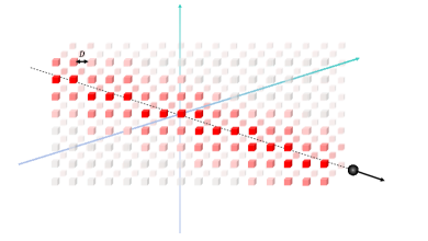
Furthermore, as previously mentioned, the pulsed signal is only generated when the particle enters the range of the SQUID. Therefore, along the trajectory of the particle, the signals from the detector occur almost sequentially in time. Therefore, we can reconstruct the trajectory and velocity of the particle by analyzing the signal strength and time sequence of all detectors 333In principle, we can increase the size of the chamber to enhance its ability to detect trajectories. However, current technology is not able to connect a large number of SQUIDs in a single circuit and effectively read them out. We can divide the setup into many smaller chambers and arrange them in regular pattern to achieve the same effect. The maximum number of SQUIDs in a readout module is discussed in Appendix B. .
The superconducting cloud chamber can also effectively eliminate the majority of environmental backgrounds. Firstly, random system backgrounds only sporadically generate signals and do not present particle trajectories. Secondly, since the detector is sensitive only to low-speed flying charged particles, signals generated by high-energy SM particles like cosmic rays cannot be detected, thus not forming background noise444Although cosmic muons may be decelerated by Earth shielding, they quickly decay to electrons and the speed of electrons is too high.. Lastly, once clear particle trajectories are identified in the chamber, confirming the presence of flying particles, we can also determine the charge of particle by analyzing the signal intensities. In the case of millicharged DM detection, the charges of SM charged particles in the background are all integers, making them easily distinguishable.
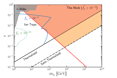
Application to Millicharged DM – As mentioned in the introduction, one application of this chamber is the detection of millicharged DM. Previous research Neufeld:2018slx ; Pospelov:2020ktu ; Leane:2022hkk ; Berlin:2023zpn has shown that long-range and strongly interacting DM can reach thermal equilibrium through multiple scatterings with the Earth’s environment. The millicharged DM is assumed to directly couples only to massless SM photons. Once its electric charge satisfies the condition Pospelov:2020ktu , , it can reach thermal equilibrium at depths of km underground (the black solid line in Fig. 4). As a result, the kinetic energy of DM equals the Earth’s temperature, approximately eV. The velocity of DM relates to its mass as .
The detectable velocity range of a charged particle in superconducting cloud chamber, , corresponds to a detectable range of the millicharged DM masses, GeV. The minimum magnetic flux that the detector can measure depends on the signal frequency, or equivalently, the DM velocity,
| (5) |
Compare it with the signal Eq. (4), one can get the sensitivity of our cloud chamber to the phase difference and then the millicharge,
| (6) |
which is the region above the red solid line in Fig. 4. Since this limit only applies to the DM thermalized with the Earth environment, its overlap (red shaded region) with region above black line is the sensitivity of the present superconducing cloud chamber to millicharged DM.
Furthermore, because of the long-time (the age of the Earth) accumulation effects, the number density of the millicharged DM in the earth also significantly increases. Depending on the fraction of the millicharged DM in the total DM , its number density is, cm Pospelov:2020ktu . To ensure the detection rate to be larger than day-1 in cm3 chamber, the DM density should be, Even for the heaviest DM mass GeV, the superconducting cloud chamber has a potential to detect the millicharged DM with a tiny fraction of .
For the DM that can not fully reached thermalization at a distance of km inside the Earth (black dashed line), a small fraction of them still have lower velocities due to distribution effects. Since the chamber has very low requirements for the DM number density, this parameter space (orange shaded region) might also be detectable.
Due to its extremely low kinetic energy, the millicharged DM thermalized in Earth cannot surpass the threshold for traditional DM direct detections Budker:2021quh ; ArguellesDelgado:2021lek ; PandaX:2023toi ; Iles:2024zka , necessitating novel experimental methods for its detection, such as electrostatic accelerator Pospelov:2020ktu , oil-drop experiment Kim:2007zzs , levitation experiments with microspheres Moore:2014yba ; Afek:2020lek , ion traps Budker:2021quh , and so on Chen:2022abz ; CUORE:2024rbd ; Ema:2024oce . For DM fraction of and , the most stringent constraints from ion-trap experiments are shown as the blue solid and green dashed lines Budker:2021quh . Because of the decrease in energy transfer efficiency and number density, this limit is not sensitive to high-mass and small-fraction parameter ranges. We also demonstrate collider search and beam dump experiment constraints as the gray region 1995ZPhyC..67..203A ; Prinz:1998ua ; Magill:2018tbb ; Berlin:2018bsc ; Kelly:2018brz ; Harnik:2019zee ; ArgoNeuT:2019ckq ; Ball:2020dnx ; Marocco:2020dqu . It can be observed that the superconducting cloud chamber has a unique advantage in the high-mass parameter range, as higher-mass millichagred DM particles have slower velocities, aligning perfectly with the sensitivity range of the detector.
Discussions and Summary – Particle tracking detectors play a crucial role in the discovery of new particles, greatly advancing the fields of particle physics. Many fundamental charged particles such as the positron and muon were discovered in Wilson cloud chamber Grupen_Shwartz_2008 . Afterwards, the bubble chamber made a series of significant discoveries Glaser:1952zz including weak neutral currents. Cherenkov detectors can also be used to detect neutral high-speed particles, such as high-energy neutrinos Bolotovskii_2009 . Recently, new tracking detectors such as wire chambers, spark chambers, drift chambers, and solid-state nuclear track detectors have been developed for a wider range of physics explorations Sauli:1977mt ; GUO2012233 . DM is typically considered as an unknown particle. Its detection can also be aided by various bubble chambers PICASSO:2012ngj ; COUPP:2012jrk ; PICO:2015amc ; PICO:2023uff .
The detection methods based on scattering and ionization used by the detectors above all have certain energy thresholds. Ionizing an atom typically requires eV of energy. This requires the kinetic energy of the incident particles to be greater than this threshold. Consequently, they can not detect the millicharged DM thermalized with the Earth’s environment and even the SM charged particles with velocity lower than .
In this paper, we propose a cloud chamber made of JJs. Due to the absence of resistance in superconductors, the energy threshold required to excite superconducting current signals is extremely low. Considering the background of circuit readout, superconducting cloud chamber can detect charged or millicharged particles traveling at speeds of . Even if it constitutes only of DM, the present superconducting cloud chamber is sensitive to millicarged DM with masses of GeV. Furthermore, this chamber can also be used to track the movement trajectories of charged particles in space or specific laboratories, opening up new avenues for the detection of low-speed charged particles.
Acknowledgements
The authors thank Tie-Sheng Yang for improving the Fig.. They also thank Hong Ding, Shao-Feng Ge, Shigeki Matsumoto, and Ning Zhou for fruitful discussions. B. G. is supported by the Innovation Program for Quantum Science and Technology (No.2021ZD0302700). J. S. is supported by the National Natural Science Foundation of China (Nos. 12375101, 12425506, 12090060, 12090064) and the SJTU Double First Class start-up fund WF220442604. T. T. Y. is supported by the Natural Science Foundation of China (NSFC) under Grant No. 12175134, MEXT KAKENHI Grants No. 24H02244, and World Premier International Research Center Initiative (WPI Initiative), MEXT, Japan.
References
- (1) B. Holdom, “Two U(1)’s and Epsilon Charge Shifts,” Phys. Lett. B 166 (1986) 196–198.
- (2) D. Feldman, Z. Liu, and P. Nath, “The Stueckelberg Z-prime Extension with Kinetic Mixing and Milli-Charged Dark Matter From the Hidden Sector,” Phys. Rev. D 75 (2007) 115001, [arXiv:hep-ph/0702123].
- (3) S. D. McDermott, H.-B. Yu, and K. M. Zurek, “Turning off the Lights: How Dark is Dark Matter?,” Phys. Rev. D 83 (2011) 063509, [arXiv:1011.2907 [hep-ph]].
- (4) E. Izaguirre and I. Yavin, “New window to millicharged particles at the LHC,” Phys. Rev. D 92 no. 3, (2015) 035014, [arXiv:1506.04760 [hep-ph]].
- (5) P. Agrawal, F.-Y. Cyr-Racine, L. Randall, and J. Scholtz, “Make Dark Matter Charged Again,” JCAP 05 (2017) 022, [arXiv:1610.04611 [hep-ph]].
- (6) D. A. Neufeld, G. R. Farrar, and C. F. McKee, “Dark Matter that Interacts with Baryons: Density Distribution within the Earth and New Constraints on the Interaction Cross-section,” Astrophys. J. 866 no. 2, (2018) 111, [arXiv:1805.08794 [astro-ph.CO]].
- (7) M. Pospelov and H. Ramani, “Earth-bound millicharge relics,” Phys. Rev. D 103 no. 11, (2021) 115031, [arXiv:2012.03957 [hep-ph]].
- (8) R. K. Leane and J. Smirnov, “Floating dark matter in celestial bodies,” JCAP 10 (2023) 057, [arXiv:2209.09834 [hep-ph]].
- (9) A. Berlin, H. Liu, M. Pospelov, and H. Ramani, “Terrestrial density of strongly-coupled relics,” Phys. Rev. D 109 no. 7, (2024) 075027, [arXiv:2302.06619 [hep-ph]].
- (10) A. Aboubrahim, P. Nath, and Z.-Y. Wang, “A cosmologically consistent millicharged dark matter solution to the EDGES anomaly of possible string theory origin,” JHEP 12 (2021) 148, [arXiv:2108.05819 [hep-ph]].
- (11) S. L. Dubovsky, D. S. Gorbunov, and G. I. Rubtsov, “Narrowing the window for millicharged particles by CMB anisotropy,” JETP Lett. 79 (2004) 1–5, [arXiv:hep-ph/0311189].
- (12) R. de Putter, O. Doré, J. Gleyzes, D. Green, and J. Meyers, “Dark Matter Interactions, Helium, and the Cosmic Microwave Background,” Phys. Rev. Lett. 122 no. 4, (2019) 041301, [arXiv:1805.11616 [astro-ph.CO]].
- (13) E. D. Kovetz, V. Poulin, V. Gluscevic, K. K. Boddy, R. Barkana, and M. Kamionkowski, “Tighter limits on dark matter explanations of the anomalous EDGES 21 cm signal,” Phys. Rev. D 98 no. 10, (2018) 103529, [arXiv:1807.11482 [astro-ph.CO]].
- (14) M. A. Buen-Abad, R. Essig, D. McKeen, and Y.-M. Zhong, “Cosmological constraints on dark matter interactions with ordinary matter,” Phys. Rept. 961 (2022) 1–35, [arXiv:2107.12377 [astro-ph.CO]].
- (15) P. C. Kim, E. R. Lee, I. T. Lee, M. L. Perl, V. Halyo, and D. Loomba, “Search for fractional-charge particles in meteoritic material,” Phys. Rev. Lett. 99 (2007) 161804.
- (16) D. C. Moore, A. D. Rider, and G. Gratta, “Search for Millicharged Particles Using Optically Levitated Microspheres,” Phys. Rev. Lett. 113 no. 25, (2014) 251801, [arXiv:1408.4396 [hep-ex]].
- (17) G. Afek, F. Monteiro, J. Wang, B. Siegel, S. Ghosh, and D. C. Moore, “Limits on the abundance of millicharged particles bound to matter,” Phys. Rev. D 104 no. 1, (2021) 012004, [arXiv:2012.08169 [hep-ex]].
- (18) D. Budker, P. W. Graham, H. Ramani, F. Schmidt-Kaler, C. Smorra, and S. Ulmer, “Millicharged Dark Matter Detection with Ion Traps,” PRX Quantum 3 no. 1, (2022) 010330, [arXiv:2108.05283 [hep-ph]].
- (19) J. Clarke, “Principles and applications of squids,” Proceedings of the IEEE 77 no. 8, (1989) 1208–1223.
- (20) L. D. Landau and V. L. Ginzburg, “On the Theory of Superconductivity,” J. Exp. Theor. Phys. 20 (1950) .
- (21) B. D. Josephson, “Possible new effects in superconductive tunnelling,” Phys. Lett. 1 (1962) 251–253.
- (22) B. D. Josephson, “The discovery of tunnelling supercurrents,” Rev. Mod. Phys. 46 (1974) 251–254.
- (23) A. K. Jain, J. E. Lukens, and J. S. Tsai, “Test for relativistic gravitational effects on charged particlesp,” Phys. Rev. Lett. 58 (1987) 1165–1168.
- (24) G. A. Ummarino and A. Gallerati, “Josephson AC effect induced by weak gravitational field,” Class. Quant. Grav. 37 no. 21, (2020) 217001, [arXiv:2009.04967 [gr-qc]].
- (25) M. Christodoulou, A. Perez, and C. Rovelli, “Detecting Planck-Scale Dark Matter with Quantum Interference,” Phys. Rev. Lett. 133 no. 11, (2024) 111001, [arXiv:2309.08238 [gr-qc]].
- (26) Y. Cheng, J. Lin, J. Sheng, and T. T. Yanagida, “Proposal for a quantum mechanical test of gravity at millimeter scale,” Sci. Rep. 14 no. 1, (2024) 30985, [arXiv:2405.16222 [hep-ph]].
- (27) Y. Cheng, J. Sheng, and T. T. Yanagida, “Detecting a fifth-force gauge boson via superconducting Josephson junctions,” Phys. Lett. B 860 (2025) 139156, [arXiv:2402.14514 [hep-ph]].
- (28) B. Dober, Z. Ahmed, K. Arnold, D. T. Becker, D. A. Bennett, J. A. Connors, A. Cukierman, J. M. D’Ewart, S. M. Duff, J. E. Dusatko, J. C. Frisch, J. D. Gard, S. W. Henderson, R. Herbst, G. C. Hilton, J. Hubmayr, Y. Li, J. A. B. Mates, H. McCarrick, C. D. Reintsema, M. Silva-Feaver, L. Ruckman, J. N. Ullom, L. R. Vale, D. D. Van Winkle, J. Vasquez, Y. Wang, E. Young, C. Yu, and K. Zheng, “A microwave SQUID multiplexer optimized for bolometric applications,” Applied Physics Letters 118 no. 6, (Feb., 2021) 062601, [arXiv:2010.07998 [astro-ph.IM]].
- (29) D. A. Bennett, J. A. B. Mates, J. D. Gard, A. S. Hoover, M. W. Rabin, C. D. Reintsema, D. R. Schmidt, L. R. Vale, and J. N. Ullom, “Integration of tes microcalorimeters with microwave squid multiplexed readout,” IEEE Transactions on Applied Superconductivity 25 no. 3, (2015) 1–5.
- (30) J. Gard, D. Becker, D. Bennett, J. Fowler, G. Hilton, J. Mates, C. Reintsema, D. Schmidt, D. Swetz, and J. Ullom, “A scalable readout for microwave squid multiplexing of transition-edge sensors,”.
- (31) J. A. B. Mates, D. T. Becker, D. A. Bennett, B. J. Dober, J. D. Gard, J. P. Hays-Wehle, J. W. Fowler, G. C. Hilton, C. D. Reintsema, D. R. Schmidt, D. S. Swetz, L. R. Vale, and J. N. Ullom, “Simultaneous readout of 128 X-ray and gamma-ray transition-edge microcalorimeters using microwave SQUID multiplexing,” Applied Physics Letters 111 no. 6, (Aug., 2017) 062601.
- (32) HOLMES Collaboration, D. T. Becker et al., “Working principle and demonstrator of microwave-multiplexing for the HOLMES experiment microcalorimeters,” JINST 14 no. 10, (2019) P10035, [arXiv:1910.05217 [physics.ins-det]].
- (33) D. A. Bennett, J. A. B. Mates, S. R. Bandler, D. T. Becker, J. W. Fowler, J. D. Gard, G. C. Hilton, K. D. Irwin, K. M. Morgan, C. D. Reintsema, K. Sakai, D. Schmidt, S. J. Smith, D. S. Swetz, J. N. Ullom, L. R. Vale, and A. L. Wessels, “Microwave squid multiplexing for the lynx x-ray microcalorimeter,” Journal of Astronomical Telescopes, Instruments, and Systems 5 no. 2, (March, 2019) 021007–. https://lens.org/027-935-516-419-894.
- (34) M. Sathyanarayana Rao et al., “Simons Observatory Microwave SQUID Multiplexing Readout - Cryogenic RF Amplifier and Coaxial Chain Design,” J. Low. Temp. Phys. 199 no. 3-4, (2020) 807–816, [arXiv:2003.08949 [astro-ph.IM]].
- (35) M. Wegner, C. Enss, and S. Kempf, “Analytical model of the readout power and SQUID hysteresis parameter dependence of the resonator characteristics of microwave SQUID multiplexers,” Supercond. Sci. Technol. 35 no. 7, (2022) 075011, [arXiv:2112.08278 [physics.ins-det]].
- (36) Y. Nakashima, F. Hirayama, S. Kohjiro, H. Yamamori, S. Nagasawa, A. Sato, S. Yamada, R. Hayakawa, N. Y. Yamasaki, K. Mitsuda, K. Nagayoshi, H. Akamatsu, L. Gottardi, E. Taralli, M. P. Bruijn, M. L. Ridder, J. R. Gao, and J. W. A. den Herder, “Low-noise microwave SQUID multiplexed readout of 38 x-ray transition-edge sensor microcalorimeters,” Applied Physics Letters 117 no. 12, (Sept., 2020) 122601.
- (37) M. Malnou, J. A. B. Mates, M. R. Vissers, L. R. Vale, D. R. Schmidt, D. A. Bennett, J. Gao, and J. N. Ullom, “Improved microwave SQUID multiplexer readout using a kinetic-inductance traveling-wave parametric amplifier,” Appl. Phys. Lett. 122 no. 21, (2023) 214001, [arXiv:2303.04181 [astro-ph.IM]].
- (38) J. Mates, “The microwave squid multiplexer,”.
- (39) R. Gross, A. Marx, and F. Deppe, Applied Superconductivity: Josephson Effect and Superconducting Electronics. De Gruyter Textbook Series. Walter De Gruyter Incorporated, 2016. https://books.google.com/books?id=4SIzrgEACAAJ.
- (40) C. A. Argüelles Delgado, K. J. Kelly, and V. Muñoz Albornoz, “Millicharged particles from the heavens: single- and multiple-scattering signatures,” JHEP 11 (2021) 099, [arXiv:2104.13924 [hep-ph]].
- (41) PandaX Collaboration, X. Ning et al., “Limits on the luminance of dark matter from xenon recoil data,” Nature 618 no. 7963, (2023) 47–50.
- (42) E. Iles, S. Heeba, and K. Schutz, “Direct Detection of the Millicharged Background,” [arXiv:2407.21096 [hep-ph]].
- (43) C.-R. Chen, B. H. Nhung, and C. S. Nugroho, “Millicharged dark matter detection with Mach-Zehnder interferometer,” Phys. Lett. B 839 (2023) 137764, [arXiv:2212.13017 [hep-ph]].
- (44) CUORE Collaboration, D. Q. Adams et al., “Search for Fractionally Charged Particles with CUORE,” Phys. Rev. Lett. 133 no. 24, (2024) 241801, [arXiv:2406.12380 [hep-ex]].
- (45) Y. Ema, M. Pospelov, and A. Ray, “Probing earth-bound dark matter with nuclear reactors,” JHEP 07 (2024) 094, [arXiv:2402.03431 [hep-ph]].
- (46) R. e. a. Akers, “Search for heavy charged particles and for particles with anomalous charge in e+e- collisions at LEP,” Zeitschrift fur Physik C Particles and Fields 67 no. 2, (June, 1995) 203–211.
- (47) A. A. Prinz et al., “Search for millicharged particles at SLAC,” Phys. Rev. Lett. 81 (1998) 1175–1178, [arXiv:hep-ex/9804008].
- (48) G. Magill, R. Plestid, M. Pospelov, and Y.-D. Tsai, “Millicharged particles in neutrino experiments,” Phys. Rev. Lett. 122 no. 7, (2019) 071801, [arXiv:1806.03310 [hep-ph]].
- (49) A. Berlin, N. Blinov, G. Krnjaic, P. Schuster, and N. Toro, “Dark Matter, Millicharges, Axion and Scalar Particles, Gauge Bosons, and Other New Physics with LDMX,” Phys. Rev. D 99 no. 7, (2019) 075001, [arXiv:1807.01730 [hep-ph]].
- (50) K. J. Kelly and Y.-D. Tsai, “Proton fixed-target scintillation experiment to search for millicharged dark matter,” Phys. Rev. D 100 no. 1, (2019) 015043, [arXiv:1812.03998 [hep-ph]].
- (51) R. Harnik, Z. Liu, and O. Palamara, “Millicharged Particles in Liquid Argon Neutrino Experiments,” JHEP 07 (2019) 170, [arXiv:1902.03246 [hep-ph]].
- (52) ArgoNeuT Collaboration, R. Acciarri et al., “Improved Limits on Millicharged Particles Using the ArgoNeuT Experiment at Fermilab,” Phys. Rev. Lett. 124 no. 13, (2020) 131801, [arXiv:1911.07996 [hep-ex]].
- (53) A. Ball et al., “Search for millicharged particles in proton-proton collisions at TeV,” Phys. Rev. D 102 no. 3, (2020) 032002, [arXiv:2005.06518 [hep-ex]].
- (54) G. Marocco and S. Sarkar, “Blast from the past: Constraints on the dark sector from the BEBC WA66 beam dump experiment,” SciPost Phys. 10 no. 2, (2021) 043, [arXiv:2011.08153 [hep-ph]].
- (55) C. Grupen and B. Shwartz, Particle Detectors. Cambridge Monographs on Particle Physics, Nuclear Physics and Cosmology. Cambridge University Press, 2 ed., 2008.
- (56) D. A. Glaser, “Some Effects of Ionizing Radiation on the Formation of Bubbles in Liquids,” Phys. Rev. 87 (1952) 665–665.
- (57) B. M. Bolotovskii, “Vavilov – cherenkov radiation: its discovery and application,” Physics-Uspekhi 52 no. 11, (Nov, 2009) 1099. https://dx.doi.org/10.3367/UFNe.0179.200911c.1161.
- (58) F. Sauli, “Principles of Operation of Multiwire Proportional and Drift Chambers,”.
- (59) S.-L. Guo, B.-L. Chen, and S. Durrani, “Chapter 4 - solid-state nuclear track detectors,” in Handbook of Radioactivity Analysis (Third Edition), M. F. L’Annunziata, ed., pp. 233–298. Academic Press, Amsterdam, third edition ed., 2012. https://www.sciencedirect.com/science/article/pii/B9780123848734000049.
- (60) PICASSO Collaboration, S. Archambault et al., “Constraints on Low-Mass WIMP Interactions on from PICASSO,” Phys. Lett. B 711 (2012) 153–161, [arXiv:1202.1240 [hep-ex]].
- (61) COUPP Collaboration, E. Behnke et al., “First Dark Matter Search Results from a 4-kg CF3I Bubble Chamber Operated in a Deep Underground Site,” Phys. Rev. D 86 no. 5, (2012) 052001, [arXiv:1204.3094 [astro-ph.CO]]. [Erratum: Phys.Rev.D 90, 079902 (2014)].
- (62) PICO Collaboration, C. Amole et al., “PICASSO, COUPP and PICO - Search for Dark Matter with Bubble Chambers,” EPJ Web Conf. 95 (2015) 04020.
- (63) PICO Collaboration, E. Adams et al., “Search for inelastic dark matter-nucleus scattering with the PICO-60 CF3I and C3F8 bubble chambers,” Phys. Rev. D 108 no. 6, (2023) 062003, [arXiv:2301.08993 [astro-ph.CO]].
- (64) S. W. Henderson et al., “Highly-multiplexed microwave SQUID readout using the SLAC microresonator radio frequency (SMuRF) electronics for future CMB and sub-millimeter surveys (Conference Presentation),” Proc. SPIE Int. Soc. Opt. Eng. 10708 (2018) 1070819, [arXiv:1809.03689 [astro-ph.IM]].
- (65) D. Jones et al., “Qualification of Microwave SQUID Multiplexer Chips for Simons Observatory,” J. Low Temp. Phys. 216 no. 1-2, (2024) 50–56.
Appendix A Appendix A – Detection of the Phase Variation
The RF-SQUID exhibits a non-linear response to charged particles. To linearize this response, a flux-ramp modulation technique is employed. A sawtooth signal with frequency and amplitude (where n is an integer) is applied to the common flux-ramping line. This induces periodic oscillations in the SQUID response. If the slew rate of the applied ramp exceeds that of any input signal, variations in the input signal appear as phase offsets during the ramp period, producing a phase shift in the SQUID response relative to its free oscillation state (i.e., without the interaction of charged particles). This phase shift can be calculated from a Fourier measurement of the SQUID response,
| (7) |
Here, represents the discrete sampling of the SQUID response, and is the modulation frequency. Typically, is required to be at least times the maximum signal frequency.
Appendix B Appendix B – Multiplexing Factor
The number of RF SQUIDs in a readout module, which we define as the multiplexing factor , can be estimated using as follows. Let be the frequency spacing between resonator tones, and be the ADC bandwidth, the multiplexing factor is then defined as . Several constraints apply to HOLMES:2019ykt : (1) must be significantly larger than the resonator bandwidth, , where is the resonantor bandwidth and is a guard factor; (2) The Nyquist-Sannon sampling theorem requires ; (3) The ramp frequency must exceed the maximum signal frequency, , where is the rise time of the charged particle (DM) signal and is a signal distortion factor. In conclusion, the multiplexing factor per ADC board is,
| (8) |
Assuming the typical values of GHz, , , and , if a signal rise time is s, the multiplexing factor per ADC board is estimated to be . If the frequency of signal becomes lower and the rise time is extended to be ms, the multiplexing factor increases to be . This multiplexing capability, which depends on the frequency of signals, has been demonstrated in TES-based CMB detector arrays Henderson:2018jlc ; Jones:2024yss .