Soliton microcombs in X-cut LiNbO3 microresonators
Abstract
Chip-scale integration of optical frequency combs, particularly soliton microcombs, enables miniaturized instrumentation for timekeeping, ranging, and spectroscopy. Although soliton microcombs have been demonstrated on various material platforms, realizing complete comb functionality on photonic chips requires the co-integration of high-speed modulators and efficient frequency doublers, features that are available in a monolithic form on X-cut thin-film lithium niobate (TFLN). However, the pronounced Raman nonlinearity associated with extraordinary light in this platform has so far precluded soliton microcomb generation. Here, we report the generation of transverse-electric-polarized soliton microcombs with a 25 GHz repetition rate in high-Q microresonators on X-cut TFLN chips. By precisely orienting the racetrack microresonator relative to the optical axis, we mitigate Raman nonlinearity and enable soliton formation under continuous-wave laser pumping. Moreover, the soliton microcomb spectra are extended to 350 nm with pulsed laser pumping. This work expands the capabilities of TFLN photonics and paves the way for the monolithic integration of fast-tunable, self-referenced microcombs.
Key words: thin film lithium niobate; optical frequency comb; optical microresonator; nonlinear photonics

Introduction
The rapid evolution of integrated photonics is driving the demand for multifunctional material platforms that support diverse on-chip optical operations. Among these platforms, thin-film lithium niobate (TFLN) has emerged as a prime candidate owing to its ultralow optical losses, robust second-order nonlinear response (), and high electro-optic efficiency () 1, 2. Traditionally employed for frequency doubling and electro-optic modulation, the performance of LiNbO3 has been remarkedly enhanced by TFLN technology through improved confinement of both optical and electrical fields2. These advances have enabled high-speed modulators 3, 4 and highly efficient frequency doublers 5, 6, 7 that surpass previous capabilities (Fig. 1). Notably, fully exploiting LiNbO3’s maximum nonlinear coefficients and electro-optic properties requires that both the optical and electric fields be aligned parallel to the crystal’s optical axis – a condition fulfilled by the transverse-electric (TE) modes in X-cut TFLN.
Chip-based optical frequency combs, or microcombs, have concurrently transformed the architectures of integrated photonics8, 9. These microcombs are indispensable for the co-integration of microwave and atomic systems in applications such as optical frequency synthesis10, timekeeping11, and advanced computational tasks12. In TFLN, microcombs are generated via resonantly enhanced nonlinear optical processes – most notably Kerr effects 13, 14, 15, 16 and electro-optic interactions 17, 18, 19 – yielding comb lines described by , where is the repetition rate and is the carrier-envelope-offset frequency. Broadband microcombs spanning more than an octave have been demonstrated in Z-cut LiNbO3 microresonators by balancing Kerr nonlinearity with anomalous dispersion, a requisite for soliton mode-locking 20, 21. However, the monolithic integration of soliton microcombs with efficient frequency doublers and high-speed electro-optic modulators is most straightforward on X-cut TFLN. In this configuration, the strong Raman response associated with extraordinary-polarized light has traditionally precluded soliton formation, instead favoring Raman lasing 22, 23, 16, 24, 25, 26.
In this work, we tailor the portion between ordinary and extraordinary light in LiNbO3 microresonators to suppress stimulated Raman scattering on X-cut TFLN. Microwave-rate ( GHz) soliton microcombs with 200 nm spectral span are generated in TE modes with a continuous-wave pump laser, whose spectra are further extended to over 350 nm using a pulsed pump laser. Our approach allows for seamless integration with existing technologies on X-cut TFLN, promising applications in optical communication27, computation12, timing11, and spectroscopy28, 29 (Fig. 1).
Results
Raman response of X-cut TFLN
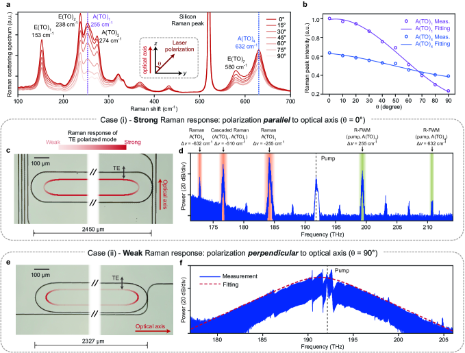
Firstly, we characterize the polarization-dependence of the Raman response of an X-cut TFLN chip using Raman spectroscopy22, 30 (Fig. 2a and Methods). The Raman spectra contain multiple peaks corresponding to different vibrational modes, with intensities decreasing as the pump polarization transitions from parallel (extraordinary light) to perpendicular (ordinary light) to the optical axis. For instance, in the measurement, the peak intensities of vibrational modes A(TO)1 and A(TO)4 are reduced to 40% and 20%, respectively (Fig. 2b). Thus, similar to the case of LiTaO3 31, incorporating more ordinary light in the modes of LiNbO3 microresonators can significantly mitigate the Raman effect, which is the key to our design.
To control the portion of ordinary light, we use racetrack microresonators instead of ring microresonators. The majority of the modes are confined in the straight waveguides, whose orientation determines the dominance of ordinary or extraordinary light. We test two racetrack microresonators with different orientations on X-cut TFLN-on-insulator chips. In device (i), the straight waveguides are perpendicular to the optical axis, such that the TE mode is polarized along the optical axis (Fig. 2c). Therefore, the Raman response of the TE mode is strong in the straight section but weak in the arc section. Measurements show that this device exhibits a loaded Q factor of approximately 1 million and anomalous group velocity dispersion, theoretically permitting soliton microcomb generation. However, the resulting optical spectrum shows Raman lasing due to interactions with vibrational modes A(TO)1 and A(TO)4 (Fig. 2d).
In contrast, in device (ii), the straight waveguides are parallel to the optical axis, and the TE mode is polarized perpendicular to the optical axis (Fig. 2e). As a result, the Raman response of the TE mode is weak in the straight section but strong in the arc section. With significantly reduced Raman nonlinearity, soliton microcombs are generated in this device, with the characteristic sech2-shaped optical spectrum shown in Fig. 2f. Detailed characterization of the device and the soliton microcombs are presented in the following sections.
Device design and characterization
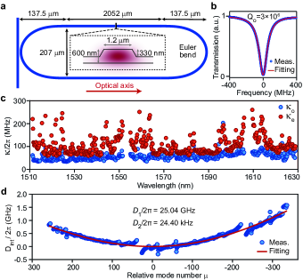
The soliton-generating microresonators are fabricated from a 600-nm-thick LiNbO3 layer atop a 4.7-µm-thick silica layer, following established procedures 16. The etching depth is 330 nm with an etching angle of 62 degrees (Fig. 3a). The waveguide’s top width is 1.2 µm, supporting two TE modes in the straight sections and one TE mode in the arc sections. The 2052-µm-long straight waveguides are connected by Euler bends to suppress spatial mode interactions and reduce losses from the straight-to-bend transitions32. The free-spectral-range (FSR) of the microresonator is approximately 25 GHz. A bus waveguide with a top width of 1 µm is coupled to the microresonator at the Euler bend. The transmitted spectrum shows an intrinsic Q factor up to 3 million within the telecommunication C-band (Fig. 3b).
The wavelength-dependent leakage of the optical mode in the arc sections indicates larger coupling losses at longer wavelengths, a feature leveraged to suppress Raman lasing in LiNbO3 microresonators 13, 26, 33, 16, 21. This is confirmed by the measured coupling and intrinsic losses of the fundamental TE mode shown in Fig. 3c. The Q factor exhibits abnormal degradation at wavelengths near 1560 nm and 1610 nm, attributed to coupling with the transverse-magnetic mode. This modal coupling is evident in the mode family dispersion (Fig. 3d), where notable deviations from parabolic fitting are observed at these wavelengths. Nevertheless, the TE mode predominantly follows anomalous group velocity, with a second-order dispersion () of 24.4 kHz.
Soliton microcombs driven by continuous-wave lasers
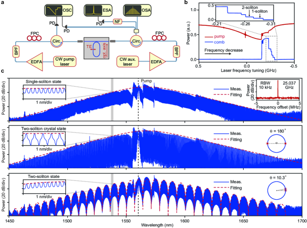
The experimental setup is illustrated in Fig. 4a, where a continuous-wave laser is amplified to pump the microresonator. The laser is tuned from the blue-detuned side to the red-detuned side of the mode to access the soliton state 34. This process is complicated by the thermo-optic effect, which red-shifts the mode with increasing intracavity power35. This behavior contrasts with Z-cut TFLN microresonators, where photorefraction 13 and pyroelectricity 36 counterbalance the thermo-optic effect. Consequently, direct tuning into the soliton state is infeasible due to the abrupt decrease in intracavity power 35, 37, 38. To mitigate thermal nonlinearity, an auxiliary laser is tuned into a counter-propagating mode of the microresonator 39, 40, 41. The powers of the pump and auxiliary lasers on the bus waveguide are 192.5 mW and 148.9 mW, respectively. The existence range of the soliton in terms of the pump laser detuning is significantly increased with optimal auxiliary laser frequency (Fig. 4b). The discrete steps in the comb power represent comb states with distinct soliton numbers.
Figure 4c presents optical spectra of different soliton states, including single-soliton, two-soliton crystal, and two-soliton states. All spectra span more than 200 nm, with deviations from the spectral envelopes caused by mode-crossings. The electrical beat note of the single-soliton state, detected with a fast photodiode, exhibits a narrow-linewidth peak at 25.037 GHz, certifying the coherent nature of the soliton microcomb. For multi-soliton states, the envelope of the generated optical spectra shows pronounced modulation due to interference between individual solitons. The relative angular positions of solitons can be reconstructed by Fourier transforming the optical spectra, as depicted in the corresponding right insets.
Soliton microcombs driven by optical pulses
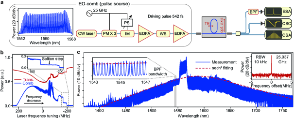
Soliton microcombs can also be generated using synchronized pulsed lasers 42, which offer higher optical-to-optical conversion efficiencies 43 and the potential to access a broader spectral range 44, 45, 46. As illustrated in Fig. 5a, we synthesize an electro-optic (EO) comb from a continuous-wave laser using cascaded phase and intensity modulators 47. Proper dispersion compensation with a programmable waveshaper generates transform-limited sinc-shaped pulses with a full width at half maximum (FWHM) of 542 fs. After amplification, an average power of 36.24 mW is launched into the bus waveguide. A bandpass filter is inserted at the output port to isolate the generated comb lines from the EO comb.
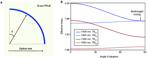
The repetition frequency of the EO comb is finely tuned around the microresonator’s FSR of 25.037 GHz until the characteristic soliton step is observed during frequency scanning (Fig. 5b). Up to two solitons are supported under the pulsed laser pump, and the improved conversion efficiency allows for adiabatic access to the soliton state 42. The optical spectrum of the single soliton state spans from 1400 nm to 1750 nm, following a sech2-shaped spectral envelope (Fig. 5c). Notably, a set of spurs deviating from the sech2 spectral envelope appears at wavelengths below 1470 nm. This deviation is attributed to birefringence-induced interaction between TE and TM modes, which occurs at shorter wavelengths 31, 48 (Extended Data Fig. 1). We use a bandpass filter centered at 1545 nm to select a portion of the generated comb lines for photodetection. The coherence of the generated comb lines is verified by their narrow-linewidth monotone electrical beat note.
Discussion
The demonstration of soliton microcomb on X-cut LiNbO3 microresonators provides a clear route toward fully integrated on-chip comb functionality. Unlike Si3N4 microcombs, the X-cut LiNbO3 platform enables monolithic integration with electrodes for high-speed modulation, thereby affording an additional degree of freedom for feedback control of both and 3, 33. Furthermore, integration with PPLN waveguides 5, 7 facilitates on-chip detection, contingent upon achieving an octave-spanning comb spectrum 20, 21 – a capability that necessitates both a higher power budget and meticulous dispersion engineering. These challenges can be overcome by employing coupled microresonators, which enhance comb generation efficiency while reducing power requirements 49, 19, 50, 51.
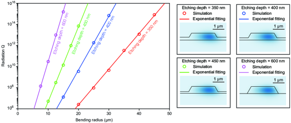
The potential applications of microcombs on this platform are broad and compelling. For example, a monolithically integrated coherent photonic transceiver may employ the microcomb as a multi-wavelength light source in conjunction with arrays of high-speed modulators. To be compatible with current wavelength-division multiplexing systems, it is advantageous to set on the order of hundreds of gigahertz—a target more readily achieved with Kerr microcombs than with EO combs driven by microwave sources17, 19, 52, 48. Notably, our approach is also applicable to smaller racetrack microresonators with larger free-spectral ranges, wherein bending losses are substantially minimized by established deep-etching techniques 53 (Extended Data Fig. 2). Furthermore, high-power combs with flattened spectral envelopes can be realized in both dark-pulse54, 16 and dissipation-engineered configurations55. Finally, by incorporating chirped PPLN waveguides56, broadband comb spectra can be efficiently converted to the visible and mid-infrared regions for atomic and molecular spectroscopy 28, 29. Collectively, these advances lay the groundwork for the realization of chip-based optical clocks 11, building on recent progress in visible laser technologies57 and photonic-integrated atomic systems58, 59, 60.
Methods
Raman spectroscopy. The Raman spectra presented in Fig. 2a are measured using Raman microscopes (LabRAM HR Evolution, Horiba). The polarization of the excitation laser is varied by rotating the half-wave plate positioned behind it, and the scattered Raman light is detected without polarization selection. Both the excitation laser and the detected Raman light propagate along the crystalline X axis, i.e. perpendicular to the chip. The intense peak at 520 cm-1 is attributed to the Raman response of the thick silicon substrate of TFLN chip. In the notations used to label vibrational modes, TO refers to transverse optical phonons, while A and E denote non-degenerate and doubly degenerate vibrational modes, respectively.
Device fabrication. Devices were fabricated on a commercial X‐cut LiNbO3-on-insulator wafer (NANOLN), which comprises a 600‐nm‐thick LiNbO3 layer atop a 4.7-µm‐thick silica buffer layer. The patterns for the bus waveguides and microrings were defined via electron‐beam lithography on a 750‐nm‐thick layer of ma–N 2405 resist. These patterns were subsequently transferred onto the LiNbO3 film using Ar+ plasma etching, yielding an etch depth of 330 nm and sidewall angles of approximately 62∘. Following the etching process, the photoresist was removed using organic solvents and oxygen plasma cleaning, and any residual redeposition was eliminated with an ammonia solution to ensure a pristine sample surface.
References
- [1] Boes, A. et al. Lithium niobate photonics: Unlocking the electromagnetic spectrum. Science 379, eabj4396 (2023).
- [2] Zhu, D. et al. Integrated photonics on thin-film lithium niobate. Adv. Opt. Photonics 13, 242–352 (2021).
- [3] Wang, C. et al. Integrated lithium niobate electro-optic modulators operating at CMOS-compatible voltages. Nature 562, 101–104 (2018).
- [4] Xu, M. et al. High-performance coherent optical modulators based on thin-film lithium niobate platform. Nat. Commun. 11, 3911 (2020).
- [5] Wang, C. et al. Ultrahigh-efficiency wavelength conversion in nanophotonic periodically poled lithium niobate waveguides. Optica 5, 1438–1441 (2018).
- [6] Lu, J. et al. Periodically poled thin-film lithium niobate microring resonators with a second-harmonic generation efficiency of 250,000%/W. Optica 6, 1455–1460 (2019).
- [7] Chen, P.-K. et al. Adapted poling to break the nonlinear efficiency limit in nanophotonic lithium niobate waveguides. Nat. Nanotechnol. 19, 44–50 (2024).
- [8] Kippenberg, T. J., Holzwarth, R. & Diddams, S. Microresonator-based optical frequency combs. Science 332, 555–559 (2011).
- [9] Chang, L., Liu, S. & Bowers, J. E. Integrated optical frequency comb technologies. Nat. Photon. 16, 95–108 (2022).
- [10] Spencer, D. T. et al. An optical-frequency synthesizer using integrated photonics. Nature 557, 81–85 (2018).
- [11] Newman, Z. L. et al. Architecture for the photonic integration of an optical atomic clock. Optica 6, 680–685 (2019).
- [12] Feldmann, J. et al. Parallel convolutional processing using an integrated photonic tensor core. Nature 589, 52–58 (2021).
- [13] He, Y. et al. Self-starting bi-chromatic LiNbO3 soliton microcomb. Optica 6, 1138–1144 (2019).
- [14] Gong, Z., Liu, X., Xu, Y. & Tang, H. X. Near-octave lithium niobate soliton microcomb. Optica 7, 1275–1278 (2020).
- [15] Gong, Z. et al. Soliton microcomb generation at 2 µm in z-cut lithium niobate microring resonators. Opt. Lett. 44, 3182–3185 (2019).
- [16] Lv, X. et al. Broadband microwave-rate dark pulse microcombs in dissipation-engineered LiNbO3 microresonators. arXiv preprint arXiv:2404.19584 (2024).
- [17] Zhang, M. et al. Broadband electro-optic frequency comb generation in a lithium niobate microring resonator. Nature 568, 373–377 (2019).
- [18] Rueda, A., Sedlmeir, F., Kumari, M., Leuchs, G. & Schwefel, H. G. Resonant electro-optic frequency comb. Nature 568, 378–381 (2019).
- [19] Hu, Y. et al. High-efficiency and broadband on-chip electro-optic frequency comb generators. Nat. Photon. 16, 679–685 (2022).
- [20] Wang, P.-Y. et al. Octave soliton microcombs in lithium niobate microresonators. Opt. Lett. 49, 1729–1732 (2024).
- [21] Song, Y., Hu, Y., Zhu, X., Yang, K. & Lončar, M. Octave-spanning Kerr soliton frequency combs in dispersion-and dissipation-engineered lithium niobate microresonators. Light Sci. Appl. 13, 225 (2024).
- [22] Schaufele, R. & Weber, M. Raman scattering by lithium niobate. Phys. Rev. 152, 705 (1966).
- [23] Okawachi, Y. et al. Competition between Raman and Kerr effects in microresonator comb generation. Opt. Lett. 42, 2786–2789 (2017).
- [24] Wang, C. et al. Monolithic lithium niobate photonic circuits for Kerr frequency comb generation and modulation. Nat. commun. 10, 978 (2019).
- [25] Yu, M. et al. Raman lasing and soliton mode-locking in lithium niobate microresonators. Light Sci. Appl. 9, 9 (2020).
- [26] Gong, Z. et al. Photonic dissipation control for soliton generation in strongly -active media. Phys. Rev. Lett. 125, 183901 (2020).
- [27] Marin-Palomo, P. et al. Microresonator-based solitons for massively parallel coherent optical communications. Nature 546, 274 (2017).
- [28] Suh, M.-G., Yang, Q.-F., Yang, K. Y., Yi, X. & Vahala, K. J. Microresonator soliton dual-comb spectroscopy. Science 354, 600–603 (2016).
- [29] Bao, C. et al. Architecture for microcomb-based GHz-mid-infrared dual-comb spectroscopy. Nat. Commun. 12, 6573 (2021).
- [30] Repelin, Y., Husson, E., Bennani, F. & Proust, C. Raman spectroscopy of lithium niobate and lithium tantalate. Force field calculations. J. Phys. Chem. Solids 60, 819–825 (1999).
- [31] Wang, C. et al. Lithium tantalate photonic integrated circuits for volume manufacturing. Nature 1–7 (2024).
- [32] Ji, X. et al. Compact, spatial-mode-interaction-free, ultralow-loss, nonlinear photonic integrated circuits. Commun. Phys. 5, 84 (2022).
- [33] He, Y. et al. High-speed tunable microwave-rate soliton microcomb. Nat. Commun. 14, 3467 (2023).
- [34] Herr, T. et al. Temporal solitons in optical microresonators. Nat. Photon. 8, 145–152 (2014).
- [35] Carmon, T., Yang, L. & Vahala, K. Dynamical thermal behavior and thermal self-stability of microcavities. Opt. Express 12, 4742–4750 (2004).
- [36] Zhang, J. et al. Fundamental charge noise in electro-optic photonic integrated circuits. Nat. Phys. 1–8 (2025).
- [37] Yi, X., Yang, Q.-F., Yang, K. Y., Suh, M.-G. & Vahala, K. Soliton frequency comb at microwave rates in a high-Q silica microresonator. Optica 2, 1078–1085 (2015).
- [38] Brasch, V. et al. Photonic chip–based optical frequency comb using soliton Cherenkov radiation. Science 351, 357–360 (2016).
- [39] Zhou, H. et al. Soliton bursts and deterministic dissipative Kerr soliton generation in auxiliary-assisted microcavities. Light Sci. Appl. 8, 50 (2019).
- [40] Zhang, S. et al. Sub-milliwatt-level microresonator solitons with extended access range using an auxiliary laser. Optica 6, 206–212 (2019).
- [41] Lu, Z. et al. Deterministic generation and switching of dissipative Kerr soliton in a thermally controlled micro-resonator. AIP Adv. 9 (2019).
- [42] Obrzud, E., Lecomte, S. & Herr, T. Temporal solitons in microresonators driven by optical pulses. Nat. Photon. 11, 600 (2017).
- [43] Li, J. et al. Efficiency of pulse pumped soliton microcombs. Optica 9, 231–239 (2022).
- [44] Obrzud, E. et al. A microphotonic astrocomb. Nat. Photon. 13, 31 (2019).
- [45] Anderson, M. H. et al. Zero dispersion Kerr solitons in optical microresonators. Nat. commun. 13, 4764 (2022).
- [46] Xiao, Z. et al. Near-zero-dispersion soliton and broadband modulational instability Kerr microcombs in anomalous dispersion. Light Sci. Appl. 12, 33 (2023).
- [47] Murata, H., Morimoto, A., Kobayashi, T. & Yamamoto, S. Optical pulse generation by electrooptic-modulation method and its application to integrated ultrashort pulse generators. IEEE J. Sel. Top. Quant 6, 1325–1331 (2000).
- [48] Zhang, J. et al. Ultrabroadband integrated electro-optic frequency comb in lithium tantalate. Nature 1–8 (2025).
- [49] Xue, X., Zheng, X. & Zhou, B. Super-efficient temporal solitons in mutually coupled optical cavities. Nat. Photon. 13, 616–622 (2019).
- [50] Helgason, Ó. B. et al. Surpassing the nonlinear conversion efficiency of soliton microcombs. Nat. Photon. 17, 992–999 (2023).
- [51] Yang, Q.-F., Hu, Y., Torres-Company, V. & Vahala, K. Efficient microresonator frequency combs. eLight 4, 18 (2024).
- [52] Yu, M. et al. Integrated femtosecond pulse generator on thin-film lithium niobate. Nature 612, 252–258 (2022).
- [53] Gao, Y. et al. Compact lithium niobate microring resonators in the ultrahigh Q/V regime. Opt. Lett. 48, 3949–3952 (2023).
- [54] Xue, X. et al. Mode-locked dark pulse Kerr combs in normal-dispersion microresonators. Nat. Photon. 9, 594–600 (2015).
- [55] Xue, X. et al. Dispersion-less Kerr solitons in spectrally confined optical cavities. Light Sci. Appl. 12, 19 (2023).
- [56] Wu, T.-H. et al. Visible-to-ultraviolet frequency comb generation in lithium niobate nanophotonic waveguides. Nat. Photon. 18, 218–223 (2024).
- [57] Lu, X. et al. Emerging integrated laser technologies in the visible and short near-infrared regimes. Nat. Photon. 18, 1010–1023 (2024).
- [58] Isichenko, A. et al. Photonic integrated beam delivery for a rubidium 3D magneto-optical trap. Nat. Commun. 14, 3080 (2023).
- [59] Hummon, M. T. et al. Photonic chip for laser stabilization to an atomic vapor with instability. Optica 5, 443–449 (2018).
- [60] Stern, L., Desiatov, B., Goykhman, I. & Levy, U. Nanoscale light–matter interactions in atomic cladding waveguides. Nat. Commun. 4, 1548 (2013).
Declarations
Ethics approval and consent to participate
Not applicable.
Consent for publication
Not applicable.
Data availability
The data that support the plots within this paper and other findings of this study are available from the corresponding author upon reasonable request.
Code availability
The codes that support the findings of this study are available from the corresponding authors upon reasonable request.
Acknowledgments
The authors thank Yaowen Hu for helpful discussions.
Funding
This work was supported by Beijing Natural Science Foundation (Z210004), National Natural Science Foundation of China (92150108), the high-performance computing Platform of Peking University, and the Advanced Photonic Integrated Center (APIC) of State Key Laboratory of Advanced Optical Communication System and Networks.
Author contributions
The experiment was conceived by B.N., X.L., C.Y., and Q.-F.Y. Measurements were performed by B.N., X.L., K.Z., and Z.W. The data was analyzed by B.N. The Raman spectroscopy was performed by G.Z., B.N., X.L., and C.Y. The device was designed by X.L. and fabricated by X.L, C.Y, and R.M. All authors contributed to writing the manuscript.
Competing interests
The authors declare no competing interests.
Additional information
Supplementary information is available for this paper.
Correspondence and requests for materials should be addressed to Q.-F.Y.