Uncovering the maximum chirality in dielectric nanostructures
Abstract
Maximum structural chirality refers to the highest selectivity for circularly polarized light (CPL) in nanostructures, often manifested as maximum circular dichroism (CD), optical rotation (OR), and spin-orbit coupling (SOC). However, the underlying physical mechanisms that lead to maximum chirality remain unclear. In this work, we demonstrate that maximum chirality in dielectric nanostructures arises from the constructive and destructive interference of multipole moments with different CPL. By employing generalized multipole decomposition, we introduce a generalized chiral multipole mechanism that allows for direct numerical calculation of CD and establishes the conditions required to achieve maximum chirality. This approach provides a comprehensive framework for analyzing chirality and serves as a foundation for future investigations of chiral nanostructures.
Structural chirality refers to the unique property of chiral nanostructures, which exhibit asymmetry in their interaction with circularly polarized light due to photonic spin-orbit coupling [1, 2, 3, 4]. This asymmetry arises from the uneven distribution of the electromagnetic field within these structures, influencing their interaction with light [5, 6]. The generation of chirality is typically linked to symmetry breaking, both in-plane and out-of-plane, which causes the electromagnetic field to behave asymmetries under different circularly polarized waves [7, 8].
Previous research aimed at enhancing chiral responses has largely focused on quantifying the asymmetry in the electromagnetic field and providing theoretical frameworks for understanding the underlying mechanisms of chirality. Key parameters, such as optical chirality density, optical chirality flow, and optical helicity, have been proposed to quantify chirality in nanostructures [9, 10, 11, 12, 13]. Despite these advances, a universal measure of electromagnetic chirality applicable to all fields and structures is still lacking [12]. For instance, while one physical quantity may remain constant for a specific structure, others may exhibit similar variation trends with circular dichroism (CD) as structural parameters change, corresponding to the mechanisms and conditions that enable a nanostructure to exhibit its strongest chiral response remain underexplored [14]. Moreover, most studies focus on quantifying the degree of chirality rather than addressing how to achieve maximum chirality.
A significant breakthrough in addressing these challenges comes from the recent progress in understanding high-Q optical resonances, particularly quasi-bound states in the continuum (Q-BICs). The discovery and exploration of Q-BICs have provided new insights into how symmetry and high-Q resonances can be leveraged to achieve strong chiral responses in nanostructures [15, 16, 17, 18, 19]. This has, in turn, opened up new directions for research aimed at realizing maximum chirality. However, designing such structures with maximum chirality often requires time-consuming and computationally expensive numerical simulations, emphasizing the need for a generalized physical framework to explain the underlying mechanisms of chirality. Recent efforts using coupled-mode theory (CMT) and reactive helicity density (RHD) have begun to illuminate these mechanisms in specific nanostructures [14, 20, 21].Yet, these approaches remain limited, as they tend to focus on particular types of chiral structures and fail to establish a general numerical relationship between chirality and the underlying physical parameters.
In this letter, for the first time, we reveal that maximum chirality in dielectric nanostructures arises from the constructive and destructive interference between multipole moments interacting with different circularly polarized waves. Using generalized multipole decomposition, we solve the reflection problem via generalized multipole scattering and introduce a generalized chiral multipole mechanism. This mechanim establishes a direct numerical relationship between chirality and generalized multipole moments. From this, we derive the generalized multipole maximum circular dichroism (GMM-CD), offering new insights into the maximum CD response of chiral dielectric nanostructures. To validate our theoretical predictions, we perform numerical simulations on various chiral dielectric nanostructures, confirming the robustness of the proposed mechanism.
We consider the chiral nanostructures located in the x-y plane and arranged in periodic order. Assuming time dependence of all fields, we consider waves polarized following the complex unit vectors:
| (1) |
For waves propagating along the negative z direction, and correspond to the right circular polarization (RCP) and left circular polarization (LCP) wave. The denoted + and - represent the results under RCP and LCP wave incident. Additionally, the reflection problem can be explained by Jones matrix. The reflection coefficient can be written as a two-dimensional column vector:
| (2) |
where and represents the amplitude ratio between incident electric field and reflected electric field in x-polarization component and y-polarization component, separately. Subsequently, the reflection coefficient for CPL can be derived from:
| (3) |
the reflection coefficients for right-handed circularly polarized (RCP) and left-handed circularly polarized (LCP) waves, denoted as and , respectively, differ primarily in the phase of their y-component, while their amplitudes are identical. This is because circularly polarized light can be viewed as a superposition of two orthogonal linear polarization components (x and y components) with a specific phase relationship. Therefore, if the reflection coefficients for the x and y components ( and ) are known, the reflection coefficients for RCP and LCP can be derived based on the phase difference. If we consider the generalized multipole scattering to appropriate the reflection of x and y polarized waves and only take backward scattering into account to calculated the reflection coefficient, the reflection coefficient in the terms of generalized multipole moments can be derived [22, 23, 24, 25, 26]. Thus, in the case of x-polarized waves:
| (4) |
in the case of y-polarized waves:
| (5) |
where is the wave number in a surronding medium ( is the wave number in vacuum, is the permittivity of sourrouding medium.), is the electric field of the normally incident plane waves at the points of multipole location, is the vacuum permittivity and is the square lattice. ED, MD, EQ, MQ represent generalized electric dipole moment, generalized magnetic dipole moment, generalized electric quadrupole moment and generalized magnetic quadrupole moment, separately[27, 28, 42]. The subscript expresses the component for each generalized multipole moment. Subsequently, the reflection coefficient under RCP and LCP waves can be obtained. For RCP waves:
| (6) |
For LCP waves:
| (7) |
From Eq. 6 and 7, The effective polarizability for RCP and LCP can be written as:
| (8) |
If we stipulate the several terms are generalized electric dipole polarizability, generalized magnetic dipole polarizability, generalized electric quadrupole polarizability and generalized magnetic quadrupole polarizability. Then the reflection coefficient can be transformed into:
| (9) |
Then the reflection spectra can be calculated by:
| (10) |
Based on the definition of largest circular dichroism (CD), we can get the CD for reflection spectra[29, 30, 31]:
| (11) |
To achieve the maximum chirality in nanostructure, the reflectance under one circularly polarized wave should reach unity, while another maintains zero, which means that the dielectric nanostructure achieves total transmission for one circularly polarized wave, at the same time
couldn’t be transmitted for another at one certain wavelength. Finally, we can get the generalized multipole maximum circular dichroism (GMM-CD):
| (12) |
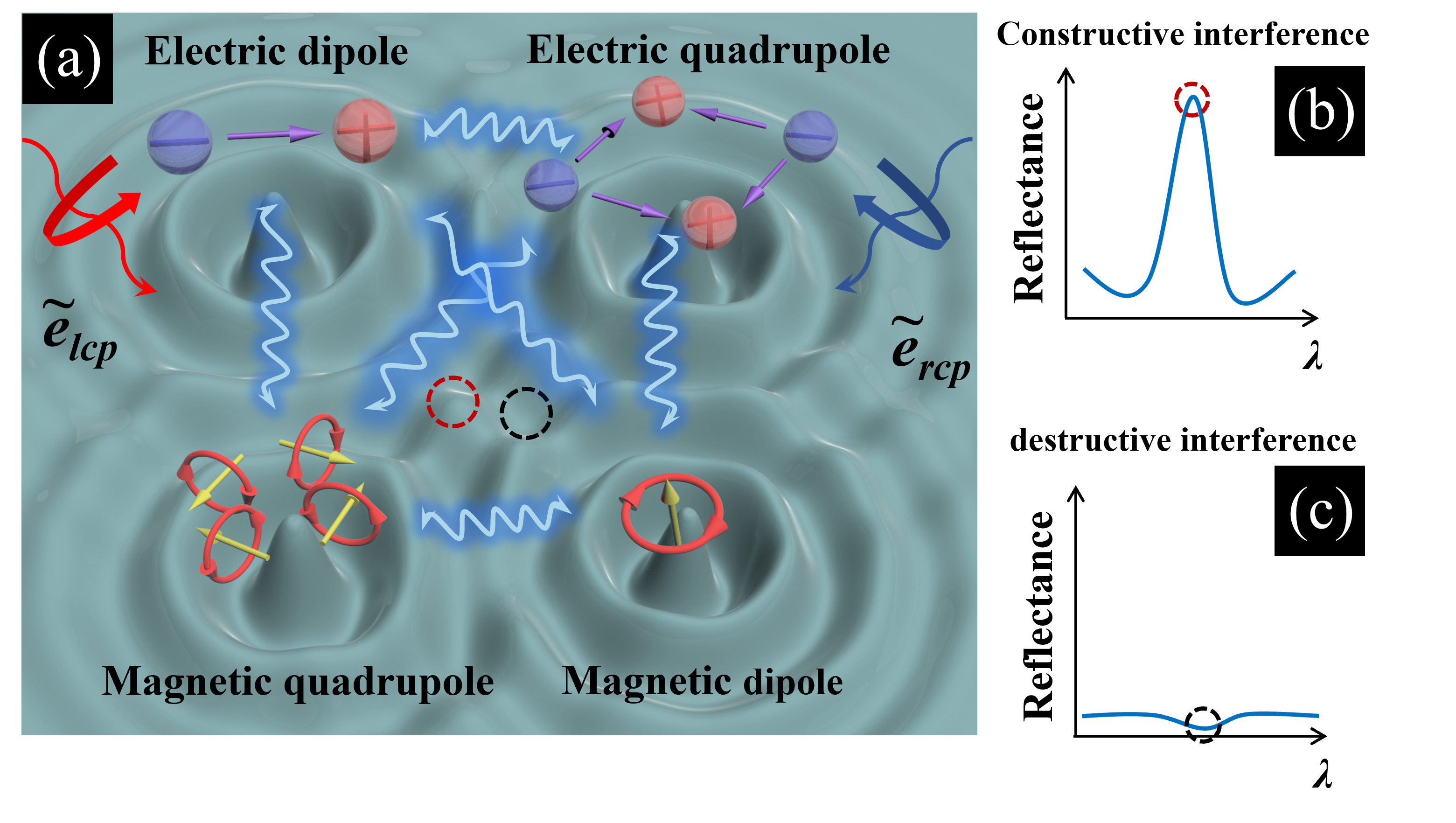
The GMM-CD may reveal a simple rules that, as shown by Fig.1, if one chiral dielectric nanostructure possess maximum chirality in one certian wavelength, for one circularly polarized wave, the interaction between different multipole moment must forms a constructive interference, causing the total reflectance. For another, the interaction must forms a destructive interference, leading to the state of total transmission, also known as anapole effect [32, 33, 34, 35, 36].
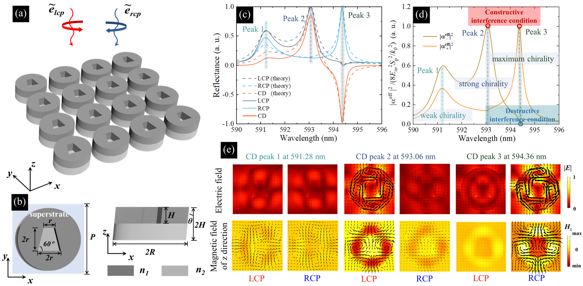
To validate our generalized chiral multipole mechanism, we numerically simulate various chiral nanostructures using COMSOL MULTIPHYSICS (additional simulations are provided in the supplymentary Material.(IV))[42]. Here, we present only one chiral nanostructure, shown in Fig. 2 (a) and (b). The unit cell of this nanostructure consists of a tilted double-layer cylinder with a tilted trapezoidal hole in the superstrate. The period P is 500 nm, the tilt angle is 8 degrees, the radius R of the cylinder is 220 nm, and both the thickness HH of the two layers and the depth of the trapezoidal hole are 100 nm. The refractive index of the superstrate is 3.44, and the refractive index of the substrate is 1.59. For simplicity, the permittivity of the surrounding medium is set to 1.
First, we simulate the reflection of normally incident RCP and LCP waves and calculate the corresponding CD spectra of the reflected light. As shown in Fig. 2(c), the chiral nanostructure exhibits three resonant modes within the wavelength range of 590 nm to 596 nm, under both RCP and LCP wave illumination. The different resonant behaviors lead to the generation of chirality. According to Eq. 11, the chiral nanostructure shows three chiral resonant states within this wavelength range. The first CD peak occurs at 591.28 nm, where the reflection for LCP waves is slightly higher than that for RCP waves, resulting in a CD value of approximately 0.16. The second CD peak is observed at 593.06 nm, where LCP waves undergo total reflection while RCP waves predominantly transmit, leading to a CD value of 0.83. The third CD peak appears at 594.36 nm, where RCP waves are totally reflected, and the array of tilted cylinders becomes more apparent under LCP waves, leading to distinct chirality and the maximum CD value.
Subsequently, we apply our generalized chiral multipole mechanism to calculate the reflection and CD spectra based on Eq. 6 and Eq. 7. As depicted in Fig. 2(c), the theoretical reflection and CD spectra also show three resonant states, which align well with the simulation results, confirming the applicability of our approach.
To further validate the principles revealed by the GMM-CD, we calculate the effective polarizability for RCP and LCP waves using Eq. 12, and examine whether they adhere to the GMM-CD rules at the three chiral resonant states. As shown in Fig. 2(d), at CD peak 1, the effective polarizability for both RCP and LCP waves does not satisfy either the constructive or destructive interference conditions, but still shows a difference, resulting in weak chirality. At CD peak 2, the effective polarizability for LCP waves reaches the constructive interference condition, while the effective polarizability for RCP waves reflects a weak destructive interference state between the generalized multipole moments, leading to strong chirality. At CD peak 3, the effective polarizability for RCP waves satisfies the constructive interference condition, while the effective polarizability for LCP waves satisfies the destructive interference condition, corresponding to the maximum chirality point. The electric field (upward) and z-component of magnetic field for three chiral resonant states is depicted in Fig. 2 (e). The arrows for upward illustrate represent the planar current distribution while for downward represent the planar magnetic field distribution. The intensity of electromagnetic response under LCP and RCP waves is getting more and more different as the intensity of chirality gets strong from peak 1 to peak 3. It is highlight that for CD peak 3 at 594.36 nm, the intensity of electromagnetic response for LCP waves is most weak among these illustration, which corresponding to the destructive interference among various generalized multipole moments.
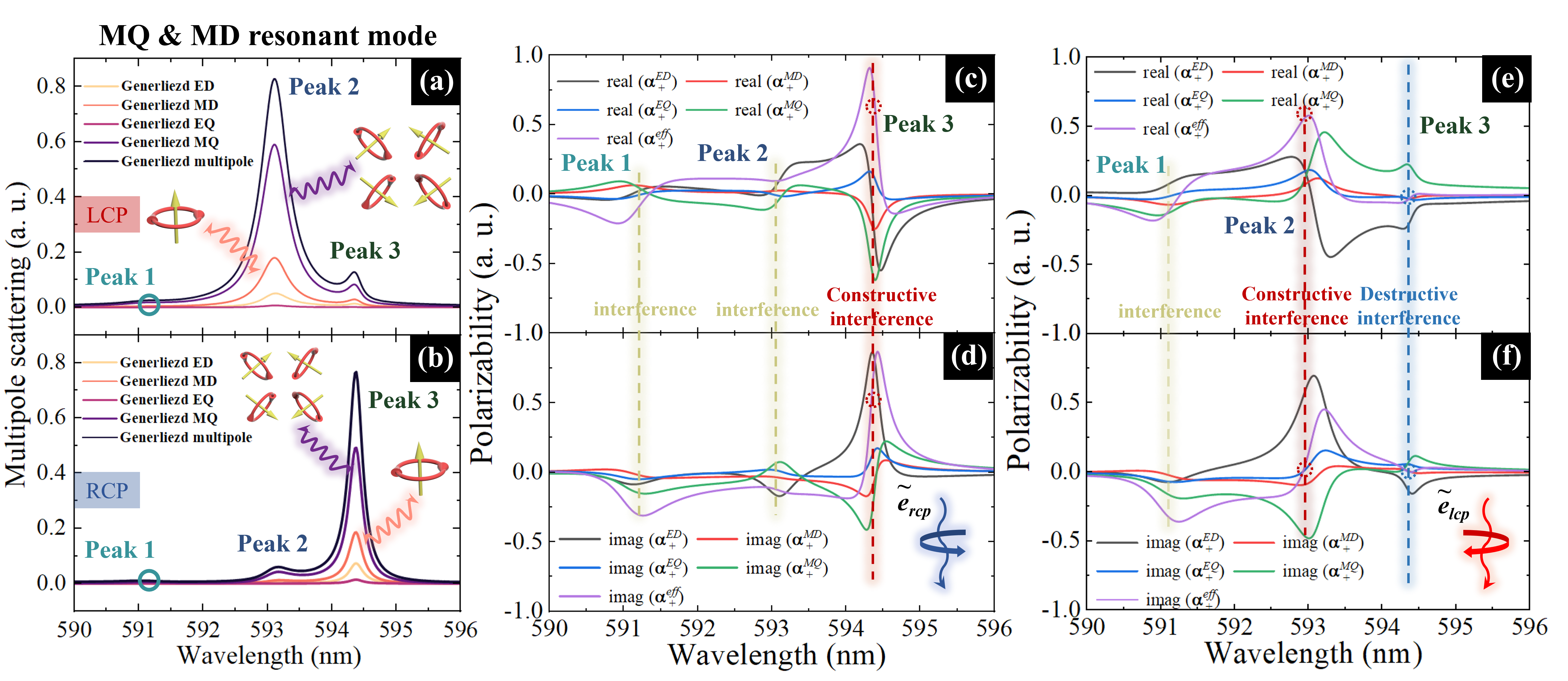
To show case the superiority of our model, we compare the traditional generalized multipole scattering method, which extensively applied in many works to investigate the resonant states and study how they induce the chirality with our generalized chiral multipole mechanism [37, 38, 39, 40, 41]. The results of generalized multipole scattering are depicted in Fig. 3 (a)-(b) and effective polarizability based on generalized chiral multipole mechanism are depicted in Fig. 3 (c)-(f). Shown in Fig. 3 (a) and (b), under RCP and LCP waves, the resonant states are dominated by MQ and MD mode while the intensity of other multipole moments remians relatively low no matter at constructive interference point or destructive interference point (details see in Supplymentary Material)[42]. And there is only difference in intensity when it is comes to the destructive interference point compared with constructive interference point. Intriguingly, for effectively polarizability of different multipole moments under RCP and LCP waves, the constructive interference is dominated by the MQ and ED mode, which differs from the results of generalized multipole scattering[see constructive interference points in Fig. 3 (c)-(f)]. At destructive interference point, the intensity of effective polarizability for MQ and ED mode is still high but their signs are opposite while other multipole moments remian near zero [see destructive interference points in Fig. 3 (e) and (f)]. The different results imply that the focuses of two physic model are different. The generalized multipole scattering mainly focus on the global scattering behavior of different multipole moment and all components of multipole are taken into account and participate in the calculation (details see in Supplymentary Material.(II)[42]). Thus, this universal method can not precisely explain the underlying mechanism of the resonance peak in the reflection spectrum and reflect the interaction between different multipole moments. Relying on Eq. (6) and Eq. (7), the resonance peaks in reflection spectrum actually mostly depend on some particular components of generalized multipole moments. Therefore, the generalized multipole scattering is actually not applicable to study how multipole moments induce strong resonance and contribute to the generation of chirality and our generalized chiral multipole mechanism provides a new and more applicable ways to replace the traditional method.
In summary, we have uncovered the physical mechanism behind maximum chirality and demonstrated how multipole interference induces this effect. We introduce the generalized chiral multipole mechanism, from which the GMMCD can be derived for chiral dielectric nanostructures Constructive interference between multipole moments leads to total reflectance for one circularly polarized wave, while destructive interference results in total transmission, known as the anapole effect, for another. The CD spectrum can be computed using specific components of the generalized multipole, and this calculation aligns well with simulation results. This mechanism highlights the interference between different multipole moments and identifies the true contributor to maximum chirality, offering a more comprehensive understanding than previous generalized multipole scattering. Our work confirms the general applicability and robustness of the theoretical framework we have developed, establishing a universal method for calculating the CD spectra. Additionally, we propose a direct numerical relationship between multipole interference and chirality in dielectric nanostructures. Our findings provide deeper insight into the origin of maximum chirality and lay a solid foundation for future research on chiral nanostructures.
Acknowldge
This work is supported by National Natural Science Foundation of China (62104174, 62205253) and Hubei Provincial Natural Science Foundation of China (2021CFB054).
† These authors contributed equally to this work.
References
- [1] J. Gautier, M. Li, T. W. Ebbesen, and C. Genet, Planar Chirality and Optical Spin–Orbit Coupling for Chiral Fabry–Perot Cavities, ACS Photonics 9, 778 (2022).
- [2] X. Zhao, J. Wang, W. Liu, Z. Che, X. Wang, C. T. Chan, L. Shi, and J. Zi, Spin-orbit-locking chiral bound states in the continuum, Phys. Rev. Lett. 133, 036201 (2024).
- [3] S. Xiao, J. Wang, F. Liu, S. Zhang, X. Yin, and J. Li, Spin-dependent optics with metasurfaces, Nanophotonics 6, 215 (2017).
- [4] F. Zhang, M. Pu, J. Luo, H. Yu, X. Luo, and others, Symmetry breaking of photonic spin-orbit interactions in metasurfaces, DOI: Opto-Electronic Engineering 44, 319 (2017).
- [5] I. Fernandez-Corbaton, M. Fruhnert, and C. Rockstuhl, Objects of maximum electromagnetic chirality, Phys. Rev. X 6, 031013 (2016).
- [6] E. Hendry, R. V. Mikhaylovskiy, L. D. Barron, M. Kadodwala, and T. J. Davis, Chiral electromagnetic fields generated by arrays of nanoslits, Nano Lett. 12, 3640 (2012).
- [7] T. Shi, Z. L. Deng, G. Geng, et al., Planar chiral metasurfaces with maximal and tunable chiroptical response driven by bound states in the continuum, Nat. Commun. 13, 4111 (2022).
- [8] J. Wu, X. Xu, X. Su, S. Zhao, C. Wu, Y. Sun, Y. Li, F. Wu, Z. Guo, H. Jiang, et al., Observation of giant extrinsic chirality empowered by quasi-bound states in the continuum, Phys. Rev. Applied 16, 064018 (2021).
- [9] D. M. Lipkin, Existence of a New Conservation Law in Electromagnetic Theory, J. Math. Phys. 5, 696 (1964).
- [10] T. W. B. Kibble, Conservation Laws for Free Fields, J. Math. Phys. 6, 1022 (1965).
- [11] M. Przanowski, B. Rajca, and J. Tosiek, On some conservation laws in the Maxwell electrodynamics in vacuum, Acta Physica Polonica. Series B 25, 1065 (1994).
- [12] Y. Tang and A. E. Cohen, Optical chirality and its interaction with matter, Phys. Rev. Lett. 104, 163901 (2010).
- [13] R. P. Cameron, S. M. Barnett, and A. M. Yao, Optical helicity, optical spin and related quantities in electromagnetic theory, New J. Phys. 14, 053050 (2012).
- [14] W. Chen, Z. Wang, M. V. Gorkunov, J. Qin, R. Wang, C. Wang, D. Wu, J. Chu, X. Wang, Y. Kivshar, et al., Uncovering maximum chirality in resonant nanostructures, Nano Lett. 24, 9643 (2024).
- [15] J. Dixon, M. Lawrence, D. R. Barton III, and J. Dionne, Self-isolated Raman lasing with a chiral dielectric metasurface, Phys. Rev. Lett. 126, 123201 (2021).
- [16] A. Overvig, N. Yu, and A. Alù, Chiral quasi-bound states in the continuum, Phys. Rev. Lett. 126, 073001 (2021).
- [17] X. Zhang, Y. Liu, J. Han, Y. Kivshar, and Q. Song, Chiral emission from resonant metasurfaces, Science 377, 1215 (2022).
- [18] L. Kühner, F. J. Wendisch, A. A. Antonov, J. Bürger, L. Hüttenhofer, L. de S. Menezes, S. A. Maier, M. V. Gorkunov, Y. Kivshar, and A. Tittl, Unlocking the out-of-plane dimension for photonic bound states in the continuum to achieve maximum optical chirality, Light: Sci. & Appl. 12, 250 (2023).
- [19] Y. Tang, Y. Liang, J. Yao, M. K. Chen, S. Lin, Z. Wang, J. Zhang, X. G. Huang, C. Yu, and D. P. Tsai, Chiral bound states in the continuum in plasmonic metasurfaces, Laser & Photonics Rev. 17, 2200597 (2023).
- [20] M. V. Gorkunov, A. A. Antonov, and Y. S. Kivshar, Metasurfaces with maximum chirality empowered by bound states in the continuum, Phys. Rev. Lett. 125, 093903 (2020).
- [21] Y. Chen, H. Deng, X. Sha, W. Chen, R. Wang, Y. Chen, D. Wu, J. Chu, Y. S. Kivshar, S. Xiao, et al., Observation of intrinsic chiral bound states in the continuum, Nature 613, 474(2023).
- [22] A. B. Evlyukhin, T. Fischer, C. Reinhardt, and B. N. Chichkov, Optical theorem and multipole scattering of light by arbitrarily shaped nanoparticles, Phys. Rev. B 94, 205434 (2016).
- [23] R. E. Raab and O. L. De Lange, Multipole theory in electromagnetism: classical, quantum, and symmetry aspects, with applications, Vol. 128, Oxford University Press, USA (2005).
- [24] L. D. Landau, The classical theory of fields, Vol. 2, Elsevier (2013).
- [25] A. B. Evlyukhin, C. Reinhardt, E. Evlyukhin, and B. N. Chichkov, Multipole analysis of light scattering by arbitrary-shaped nanoparticles on a plane surface, J. Opt. Soc. Am. B 30, 2589 (2013).
- [26] P. D. Terekhov, V. E. Babicheva, K. V. Baryshnikova, A. S. Shalin, A. Karabchevsky, and A. B. Evlyukhin, Multipole analysis of dielectric metasurfaces composed of nonspherical nanoparticles and lattice invisibility effect, Phys. Rev. B 99, 045424 (2019).
- [27] A. K. Ospanova, A. Basharin, A. E. Miroshnichenko, and B. Luk’yanchuk, Generalized hybrid anapole modes in all-dielectric ellipsoid particles, Opt. Mater. Express 11, 23 (2020).
- [28] V. R. Tuz and A. B. Evlyukhin, Polarization-independent anapole response of a trimer-based dielectric metasurface, Nanophotonics 10, 4373–4383 (2021).
- [29] Y. Cui, X. Wang, H. Jiang, and Y. Jiang, High-efficiency and tunable circular dichroism in chiral graphene metasurface, J. Phys. D: Appl. Phys. 55, 135102 (2021).
- [30] Y. Zeng, J. Xu, W. Xiao, Z. Yang, H. Chen, and Y. Liu, Giant 2D-chiroptical response in an achiral metasurface integrated with black phosphorus, Opt. Express 30, 8266 (2022).
- [31] H. Tang, D. Rosenmann, D. A. Czaplewski, X. Yang, and J. Gao, Dual-band selective circular dichroism in mid-infrared chiral metasurfaces, Opt. Express 30, 20063 (2022).
- [32] V. Savinov, N. Papasimakis, D. P. Tsai, and N. I. Zheludev, Optical anapoles, Commun. Phys. 2, 69 (2019).
- [33] E. A. Gurvitz, K. S. Ladutenko, P. A. Dergachev, A. B. Evlyukhin, A. E. Miroshnichenko, and A. S. Shalin, The high-order toroidal moments and anapole states in all-dielectric photonics, Laser & Photonics Rev. 13, 1800266 (2019).
- [34] R. Colom, R. McPhedran, B. Stout, and N. Bonod, Modal analysis of anapoles, internal fields, and Fano resonances in dielectric particles, J. Opt. Soc. Am. B 36, 2052 (2019).
- [35] I. Allayarov, A. C. Lesina, and A. B. Evlyukhin, Anapole mechanism of bound states in the continuum in symmetric dielectric metasurfaces, Phys. Rev. B 109, L241405 (2024).
- [36] Y. Yang and S. I. Bozhevolnyi, Nonradiating anapole states in nanophotonics: from fundamentals to applications, Nanotechnology 30, 204001 (2019).
- [37] B. Yang, W. Liu, Z. Li, H. Cheng, D.-Y. Choi, S. Chen, and J. Tian, Ultrahighly saturated structural colors enhanced by multipolar-modulated metasurfaces, Nano Lett. 19, 4221 (2019).
- [38] Y. Cai, Y. Huang, K. Zhu, and H. Wu, Symmetric metasurface with dual band polarization-independent high-Q resonances governed by symmetry-protected BIC, Opt. Lett. 46, 4049 (2021).
- [39] H. Zhong, L. Huang, S. Li, C. Zhou, S. You, L. Li, Y. Cheng, and A. E. Miroshnichenko, Toroidal dipole bound states in the continuum in asymmetric dimer metasurfaces, Appl. Phys. Rev. 11, 3 (2024).
- [40] G. Zhu, S. Yang, and J. C. Ndukaife, Merging toroidal dipole bound states in the continuum without up-down symmetry in Lieb lattice metasurfaces, Nanophotonics 13, 1561 (2024).
- [41] Q. Yang, Z. Yao, L. Xu, Y. Dou, L. Ba, F. Huang, Q. Xu, L. Cong, J. Gu, J. Yang, et al., Ultrasensitive Terahertz Fingerprint Retrieval with Multiple-BIC-Enabled Meta-Sensors, Laser & Photonics Rev. 2400825, 2024.
- [42] See Supplymentary Material that includes the following sections:(I.) Detail derivation for generalized chiral multipole mechansim. (II.) Generalized multipole scattering cross section. (III.) Electromagnetic field for the chiral nanostructures in text. (IV.) Bilayer cylinder metasurface. (V.) Bilayer photonic crystal slab..
Supplementary Material for:
Uncovering the Maximum Chirality in Dielectric Nanostructures
WenKui Zhao1,†, ShengYi Wang1,†, Hanzhuo Kuang1, Luo Hao1, Qiu Wang1 and Bo-Wen Jia1,*
1School of Information Engineering, Wuhan University of Technology, Wuhan 430070, China
2Key Laboratory of Artificial Micro- and Nano-structures of Ministry of Education, and School of Physical and Technology, Wuhan University, Wuhan 430072, China
The Supplymentary Material includes the following sections:(I.) Detail derivation for generalized chiral multipole mechansim. (II.) Generalized multipole scattering cross section. (III.) Electromagnetic field for the chiral nanostructures in text. (IV.) Bilayer cylinder metasurface. (V.) Bilayer photonic crystal slab.
I.Detail derivation for generalized chiral multipole mechanism.
To analyze chiral nanostructures in the x-y plane arranged periodically, we consider waves with time dependence , polarized following complex unit vectors:
| (S1) |
For waves propagating along the negative z-direction, and correspond to right (RCP) and left (LCP) circular polarization. The reflection coefficients for RCP and LCP waves are derived from the Jones matrix representation of the reflection coefficients and , defined as:
| (S2) |
These represent the amplitude ratios of incident and reflected electric fields in x- and y-polarizations. Using these coefficients, the reflection coefficients for CPL are given by:
| (S3) |
These coefficients reflect the phase relationship inherent in circularly polarized light as a combination of orthogonal linear polarizations. The reflection and transmission problem are strongly related to the electromagnetic scattering performance, which can be described by multipole scattering [22, 23, 24, 25, 26]. If the dipole moments, quadrupole moments, mean-square radii are all taken into account, the generalized multipole moments can be derived [27, 28]. The dipole moments, quadrupole moments and homologous mean-square radii interference and can induce hybrid anapole effect, the generalized multipole moments are proposed to capture this effect and provide a more precise basis to solve the reflection and transmission problem.
| Category | Expression |
|---|---|
| Dipole moments | |
| Quadrupole moments | |
| Mean-square radii | |
| Generalized multipole |
The mathematical expressions are depicted in table. 1, where , and represent the component of electric dipole, magnetic dipole and toroidal dipole, and and represent the component of electric quadrupole, magnetic quadrupole and toroidal quadrupole moment, , and represent the component of mean-square radii for magnetic dipole, toroidal dipole and magnetic quadrupole moment, the , , and represent the component of generalized electric dipole, magnetic dipole, electric quadrupole and magnetic quadrupole moments. is the wave vector, is the permittivity of a surrounding medium and is the speed of light in vacuum.
| (S4) |
where is the unit vector indicating the scattering direction, and are generalized electric dipole and magnetic dipole moment, and are the symmetrized and traceless tensors of generalized electric quadrupole and magnetic quadrupole moments. is the wave vector in the surrouding medium and is the speed of light in the surrouding medium. If we approximate the refelction and transmission problem by backward and forward scattering of generalized multipole moments that we inserting where or into the Equation.S4 to calculate the reflection and transmission coefficient. Thus, in the case of x-polarization:
| (S5) | ||||
| (S6) |
in the case of y-polarization:
| (S7) | ||||
| (S8) |
Subsequently, we only consider the reflection problem due to for dielectric nanostructures, the reflection problem is actually equal to transmission problem. Inserting the Eq. S5 and S7 into S3, the reflection coefficient for circularly polarized waves can be obtained, for RCP waves:
| (S9) |
for LCP waves:
| (S10) |
From Eqs.S9 and S10, the effective polarizability for RCP and LCP can be expressed as:
| (S11) |
Here, the terms correspond to generalized electric dipole, magnetic dipole, electric quadrupole, and magnetic quadrupole polarizabilities (see in table. 2).
| Category | Expression |
|---|---|
| Generalized electric dipole polarizability () | |
| Generalized magnetic dipole polarizability () | |
| Generalized electric quadrupole polarizability () | |
| Generalized magnetic quadrupole polarizability () |
Then, the reflection coefficient and reflection spectra becomes:
| (S12) |
| (S13) |
The largest circular dichroism (CD) for the reflection spectra is defined as:
| (S14) |
To achieve maximum chirality in a nanostructure, the reflectance under one circularly polarized wave must reach unity while the other remains zero. This indicates that the dielectric nanostructure achieves total transmission for one circularly polarized wave while completely blocking the other at a specific wavelength. The generalized multipole maximum circular dichroism (GMM-CD) can be expressed as:
| (S15) |
as shown by Eq.S15, the GMM-CD may reveal a simple rule: for a chiral dielectric nanostructure exhibiting maximum chirality at a specific wavelength, the interaction between different multipole moments forms constructive interference for one circularly polarized wave, resulting in total reflectance. Conversely, for the other circularly polarized wave, the interaction forms destructive interference, leading to total transmission—a phenomenon also known as the anapole effect.
II.Generalized multipole scattering cross section
Considering the first few spherical multipoles in the Cartesian basis, the scattering cross section (SCS), defined as the ratio of scattered power to the incident wave intensity, can be expressed as a sum of contributions from electric dipoles, magnetic dipoles, and higher-order multipoles. Considering the generalized multipole moments, the scattering cross section can be obtained:
| (S16) |
These multipole moments can be calculated by the mathematical expressions in table. 1. The generalized multipole scattering cross section theory is a universal approach that primarily focuses on the overall scattering behavior of different multipole moments. The scattering cross section declines when dipole moments, quadrupole moments and mean-square radii interferences forming a hybrid anapole states. In this framework, all components of various multipole moments—such as dipole moment, quadrupole moments and mean-square radii are included in the calculations, providing a comprehensive description of the scattering properties of nanostructures. However, the main limitation of this approach lies in its inability to precisely explain the underlying mechanisms of resonance peaks in the reflection spectrum or to reflect the interactions between different multipole moments. Specifically, the physical origin of resonance peaks often depends on specific components of the multipole moments rather than their aggregate contributions.
Based on the analysis of Eq. (S5) and Eq. (S7), it becomes evident that the resonance peaks in the reflection spectrum are primarily determined by certain particular components of the generalized multipole moments. This indicates that, while the generalized multipole scattering theory effectively describes the global scattering behavior, it is less suitable for investigating how individual multipole moments induce strong resonances and contribute to the generation of chirality. Thus, this theory falls short in uncovering the fundamental mechanisms underlying the enhancement of chirality.
The generalized chiral multipole mechanism we proposed offers a more targeted and applicable method. Compared to traditional approaches, this mechanism accurately captures the interactions between specific components of the multipole moments and elucidates how these interactions lead to resonance enhancement and the emergence of chirality. This new mechanism not only bridges the gap left by the generalized multipole scattering theory but also provides a novel theoretical tool for exploring the role of multipole moments in nanophotonics and chiral optics. By introducing this approach, we pave the way for a deeper understanding of the physical mechanisms behind chirality and for the design of nanostructures with tailored optical properties.
(III.) Resonant mode for the chiral nanostructures in text.
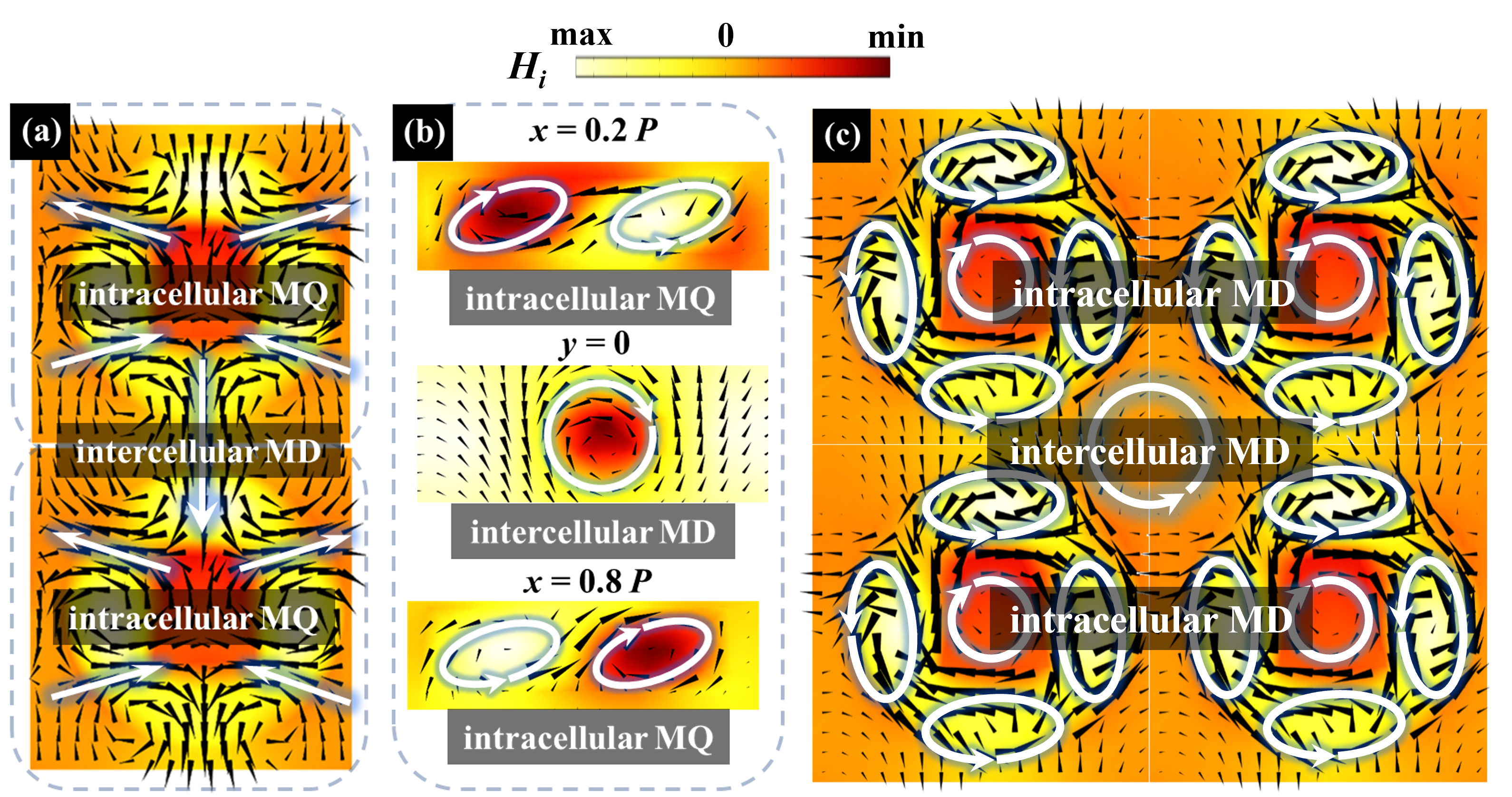
As shown in Fig.3 (a), the proposed chiral nanostrucrtures are dominated by generalized MQ and MD mode. Here in Fig. S1, we represent vertical component of magnetic field and planar component of magnetic field ( see in Fig. S1 (a) )displacement current ( see in Fig. S1 (b) and (c) ) for different planes. In Fig. S1 (a), it is shown that the chiral nanostructures form intracellular MQ and intercellular MD mode. To further validate the existence of intracellur MQ and intercellular MD mode, vertical component of magnetic field for , and planes where array present the planar component of displace current are depicted in Fig. S1 (b). In and plane, the displacement current vibrates and forms two current loop following different direction of rotation, which correspond to two unparallel magnetic dipoles. The total four MD form the intracellur MQ. In y = 0 plane, it is clear to see that the displacement current oscillates and form one current loop corresponding to one intercellular MD mode following negative y-direction, confirming the existence of intercellular MD mode. In this section, we only present the field distribution at 594.36 nm under right circularly polarized (RCP) waves. The field distributions for other resonant peaks are similar; therefore, they are not displayed separately.
(IV.) Bilayer cylinder metasurface.
Here we show that one nanostructue even without structural chirality, the generalized chiral multipole mechanism is still applicable to calculate the reflection and transmission spectra.
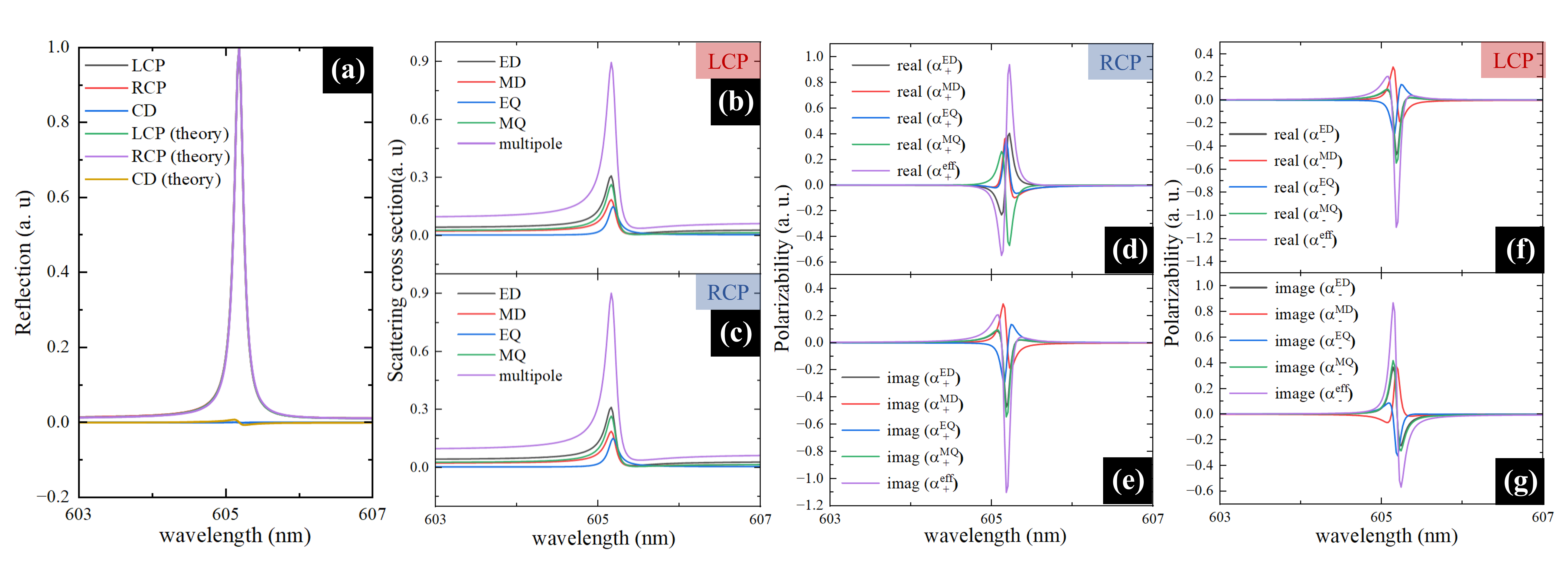
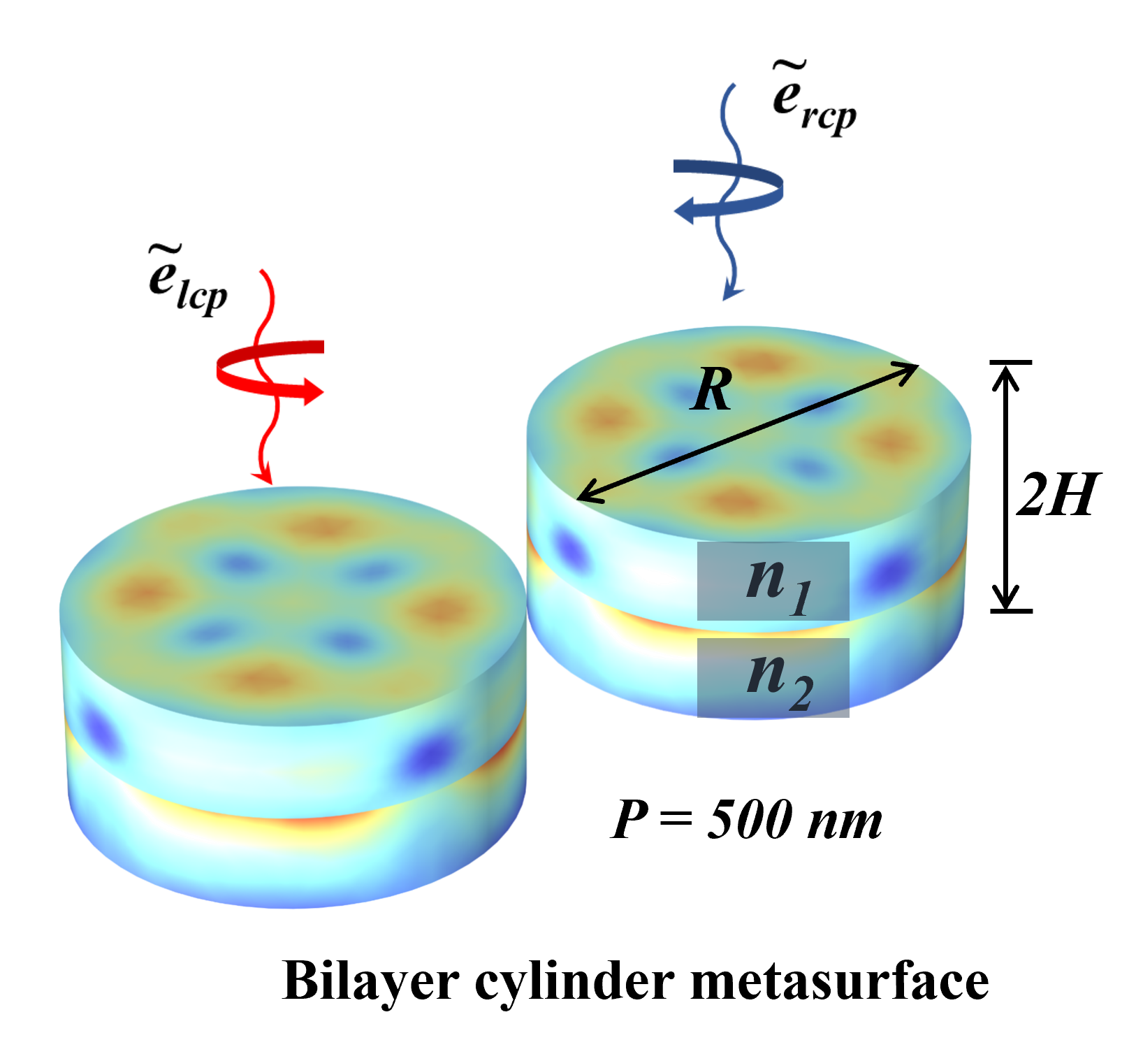
In this section, we apply generalized chiral multipole mechanism in bilayer cylinder metasurface. As depicted in Fig.S2, the unit cell of bilay cylinder metasurface is consist of two layer cylinders where the refractive index of superstrate is 3.44 and the refractive index of substrate is 1.59. The period P is 500 nm, the raidus R is 220 nm and the thickness H is 100 nm. The near fields of bilayer cylinder possess almost no difference under LCP and RCP waves, few asymmetry in total electric field amplitude may imply that this structure do not possess structural chirality, confirming by further simulation work.
The bilayer cylinder metasurface shows a resonant point near 605nm (see Fig.S3 (a)). The reflection spectra exhibits no difference under LCP and RCP waves, validating the results from Fig.S2. The reflection and CD spectra calculated by our theory fit well with the simulation results, the error in CD spectra may arise from some not- considered multipole items like octupole moments. Subsequently, the scattering cross section is shown in Fig.S3 (b) and (c). Under LCP and RCP waves, there is few difference for the scattering cross section, and the scattering fields are dominated by generalized ED and MQ mode. The effective polarizability for different generalized multipole is shown in Fig.S3 (d)-(g). The effective polarizability based on generalized chiral multipole mechanism elaborately presents more details about multipole interference than scattering cross section.