Emission and Coherent Control of Levitons in Graphene
1SPEC, CEA, CNRS, Université Paris-Saclay, CEA Saclay, 91191 Gif-sur-Yvette Cedex, France.
2Université Paris-Saclay, CNRS, Centrale Supélec, 91191 Gif-sur-Yvette Cedex, France.
3Department of Physics, Korea Advanced Institute of Science and Technology, Daejeon 34141, Korea.
4National Institute for Materials Science, 1-1 Namiki, Tsukuba 305-0044, Japan.
5NTT Basic Research Laboratories, NTT Corporation, 3-1 Morinosato-Wakamiya, Atsugi 243-0198, Japan.
*These authors contributed equally to this work.
†Corresponding author. Email: preden.roulleau@cea.fr
Abstract
Flying qubits encode quantum information in propagating modes instead of stationary discrete states. Although photonic flying qubits are available, the weak interaction between photons limits the efficiency of conditional quantum gates. Conversely, electronic flying qubits can use Coulomb interactions, but the weaker quantum coherence in conventional semiconductors has hindered their realization. In this work, we engineered on-demand injection of a single electronic flying qubit state and its manipulation over the Bloch sphere. The flying qubit is a Leviton propagating in quantum Hall edge channels of a high-mobility graphene monolayer. Although single-shot qubit readout and two-qubit operations are still needed for a viable manipulation of flying qubits, the coherent manipulation of an itinerant electronic state at the single-electron level presents a highly promising alternative to conventional qubits.
Flying qubit experiments rely on the ability to encode information into a propagating state of a single photon or electron excitation, manipulate the information, and read it after operations [1]. Photon flying qubits evolve in the vacuum, which substantially reduces decoherence processes. Conversely, electron flying qubits naturally experience a strong and tunable Coulomb interaction, which leads to easier two-qubit operations but gives rise to finite decoherence.
Electronic flying qubits can benefit from recent breakthroughs of electron quantum optics in GaAs heterostructures, including the Mach-Zehnder interferometer (MZI) [2, 3, 4], Hong-Ou-Mandel experiments [5, 6], robust high-fidelity single-electron sources based on Levitons (voltage pulses with a Lorentzian profile enabling pure-electron excitation without any hole) [6, 7], and the demonstration of single-electron quantum tomography [8]. Nevertheless, a basic quantum manipulation of an on-demand and propagating single electron is still missing [9], primarily owing to the short coherence length[3] of excited electrons in conventional semiconductors. This problem could be solved by using graphene, a two-dimensional atomically thin material, which shows outstanding coherence properties under relatively large bias [10, 11]. Owing to its valley pseudospin degrees of freedom, graphene provides a very promising platform.
Recently, it was shown that the valley degrees of freedom in graphene can be addressed electrostatically [12, 13, 14, 15, 16, 17]. In particular, coherent and tunable electronic beam splitters, which couple quantum Hall edge channels with opposite valley polarizations, were formed [10, 18, 19]. Then, an electronic MZI along a PN junction was realized by placing two valley beam splitters at both ends of the junction. However, quantum manipulation at the single-electron level, a crucial prerequisite for realizing electronic flying qubits, is still lacking in graphene. One primary reason is the absence of an electron pump, which generally requires dynamical control of quantum dots. This is extremely challenging in graphene because of the absence of a bandgap, unlike in conventional semiconductors.
In this work, we show that Levitons can be a reliable option for the injection of single electrons. Then, we demonstrate Bloch sphere rotation manipulations, taking advantage of the valley degrees of freedom in graphene MZI. This validates that the quantum coherence of the graphene MZI can be more than a few micrometers in length under high-frequency excitations. The information on final states is read statistically by combining conductance and noise measurements while periodically repeating the qubit operation.
On-demand injection of single electrons in graphene
In conventional semiconductors, different techniques for controlling on-demand electron excitation have been developed. The electron pump, composed of a series of tunnel barriers with an island or a dot, is one of them [20]. Fast manipulation of the tunnel barriers enables sequential emission of electrons. In this case, electrons are injected well above the Fermi energy, which should limit Coulomb interactions with electrons from the Fermi sea. However, because the electron excitations are far from the Fermi surface, there is more room to excite electron-hole pairs out of the ground state, leading to a very short relaxation length [21]. For graphene, although the development of well-defined quantum dots is an active field [22], their fabrication remains challenging and an electron pump has not been demonstrated.
An alternative approach to on-demand single-electron injection is a direct application of a voltage pulse , where is time, on the emitter contact, with the condition that the Faraday flux is an integer value, where is the charge of the electron and is Planck’s constant. More specifically, it has been demonstrated that by shaping the pulse as a Lorentzian function, a single electron can be emitted without the creation of unwanted electron-hole pairs [23, 24]. This excitation has been called Leviton. In addition to its simplicity, this approach allows for the emission of electrons very close to the Fermi energy, where there is minimal room for electron-hole pair creation, thereby protecting the emitted electron from possible relaxation and decoherence. In the following sections, we present a demonstration of on-demand single-electron injection based on Levitons in graphene.
Coherent manipulation and reading of the graphene qubit
The next step was to demonstrate the coherent manipulation of single electrons during propagation. The most elementary quantum manipulation is the rotation of a single qubit on the Bloch sphere. This can be achieved through an electronic MZI, which can be formed in graphene by mixing two N- and P-type edge channels with opposite valley isospin in the bipolar quantum Hall regime [10].
At the first electron beam splitter of the interferometer, the degree of valley-channel mixing can be characterized by a transmission probability and a reflection probability of the beam splitter. The initial state of an electron defined after the first beam splitter can be written as a quantum-mechanical superposition
where we introduce the channel mixing angle with and , where is a reflection coefficient.
The valley superposition state evolves by acquiring the Aharonov-Bohm phase (which is equal to , where is the magnetic field, is the interferometer area, and is the flux quantum) along the MZI. The final state at arrival at the second beam splitter becomes
Therefore, beam splitters combined with the Aharonov-Bohm effect enable the basic operations of a valley-isospin flying qubit.
After the electron passes through the second beam splitter, the final state is measured by projecting it on the output left state , with , where represents the transmission probability of the second beam splitter. We measured the transmission probability of the MZI as and the associated noise. Using the noise measurement, we show that the fundamental property of a Leviton, namely the minimization of the number of electron-hole pairs, is preserved during its propagation through the interferometer.
Voltage-pulse generation
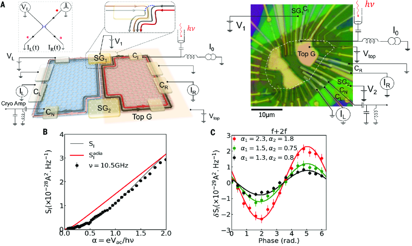
The sample we used is depicted in Fig. 1A. A global graphite back gate and a metallic top gate (labeled as Top G in Fig. 1A) are deposited on the right half of the sample in order to independently tune the electron density in the left and right halves of the sample. An electronic MZI can be formed in the bipolar quantum Hall regime [10, 18, 19, 25, 26, 27, 28]. The filling factors of the N and P regions are set to and , respectively, resulting in four copropagating channels along the PN junction. It has been shown that edge channels from the N and P regions with opposite valley polarization can be mixed by adjusting upper () and lower () side gates placed at the intersection between the PN junction and the physical edge of graphene [10].
We first consider the case where the valley beam splitter is formed only at the upper edge, which can be obtained by setting the filling factors below the upper and lower side gates to and , respectively. We constructed periodic Lorentzian pulses by summing a series of harmonics with controlled amplitude and phase. Because the amplitude and phase of the pulse change during the propagation along the electromagnetic lines in the cryostat, the pulse emitted at the output of the generator at room temperature and the one that propagates along the lines of the cryostat into the sample at base temperature are different (Fig. 1A). To resolve this issue, it was crucial to determine the amplitude and phase of each harmonic that is required to build periodic Lorentzian pulses “in situ” by measuring the photoassisted shot noise [7]. To this end, we first considered the simplest case with a single mode (). A sinusoidal potential at frequency is applied on the upper right ohmic contact (), and the shot noise is measured at the lower left ohmic contact ().
By coherent scattering at the MZI, this generates a photoassisted shot noise, which is characterized by shot-noise singularities at [29, 30, 31], where is the superimposed dc bias, is an integer, and is frequency. The exact number of electron-hole pairs is computed by comparing measured photoassisted shot noise with established theoretical expectations [6, 32] [see also, “Theoretical predictions” section in SI]. The excess noise at the thermal equilibrium generated by the partitioning of electron-hole pairs at the first beam splitter can be expressed as
where is the temperature in frequency units, is the photon number, is the Bessel function ( is an integer), and
is the typical scale of the photoassisted shot noise ( is the transmission probability of one edge channel). Note that the presence of the factor 2 is caused by the two modes involved in the partitioning at the and configurations. The agreement with the theoretical photoassisted shot noise confirms that the amplitude at the injection contact can be precisely determined (Fig. 1B). Next, to determine the phase, we measured the shot noise while varying the phase difference between the two harmonics, which defines the biharmonic signal
where , , and . In Fig. 1C,
is plotted as a function of for . By comparing the results with the photoassisted theory in SI, we could accurately adjust at the injection contact. We repeated this process for the third and fourth harmonics (see Fig. S10 for a calibration). Combined with the amplitude control, this result demonstrates that it is possible to engineer any pulse shape at the injection contact [see also the detailed discussion in section, “Engineering voltage pulses,” section in SI].
Having established that constructing a Lorentzian pulse is possible, we performed energy spectroscopy of the Fermi sea with the Lorentzian perturbation to demonstrate the minimization of electron-hole pair generation.
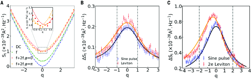
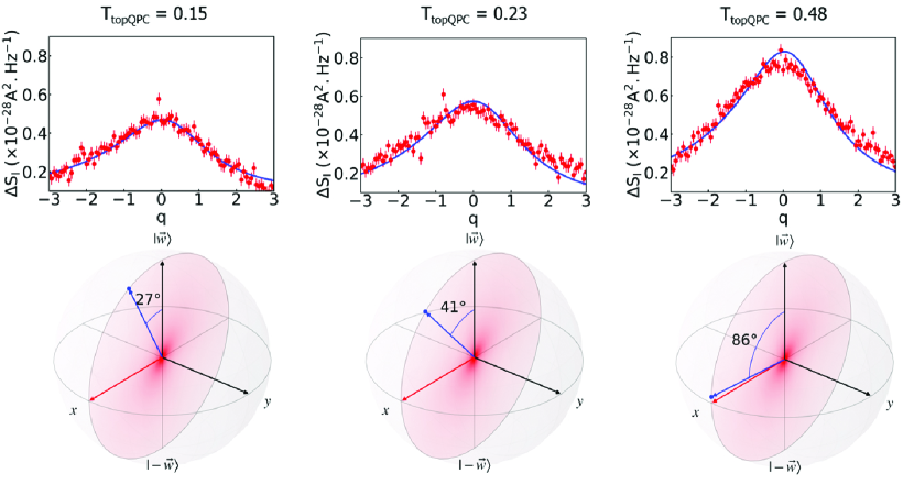
The idea was to apply a direct current (dc) on the upper-left ohmic contact, defining a voltage , while the Lorentzian pulse is applied on the opposite right contact . Under negative bias, electrons emitted in the energy range , where is energy, will antibunch with electron excitations coming from the driven right contact, resulting in no noise (see also Figs. S13 and S14). The noise variation with gives a measure of the number of electron excitations. The same procedure was repeated with positive bias to extract the number of hole excitations. Figure 2A shows the photoassisted shot noise as a function of the dc bias for single and two-harmonic modes (at and ), which agrees well with the theoretical prediction for any injected charge , which is an important requirement for the injection of Leviton () and 2e-Leviton (). In Fig. 2, B and C, the excess shot noise , obtained by subtracting the noise with “off” from the noise with “on,” is shown for a Lorentzian pulse constructed by summing four harmonics with (Leviton configuration) and (2e-Leviton configuration). The asymmetry of the excess noise reflects the absence of hole creation by the Lorentzian pulse [see also “Excess noise from sine and Lorentzian excitations” section in SI]. By comparing it to the computed excess noise for an ideal Lorentzian pulse (solid orange line), we experimentally verified that one or two electrons are injected along with a minimum amount of electron-hole pairs (at finite temperature thermal excitations add an extra contribution to the excess noise). This constitutes an experimental demonstration of on-demand single-electron injection in graphene quantum Hall edge channels. Note that for one- and two-electron Levitons, we did not observe any deviation from the non-interacting theory [see also “Relevance of the electronic interactions” section in SI]. This measurement can be realized at different values of the transmission, which demonstrates the polar angle control of the 2e-Leviton state (Fig. 3).
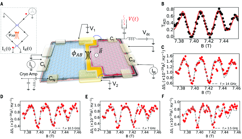
Coherent manipulation on the Bloch sphere We then turned on the lower beam splitter to showcase the coherent manipulation of single electrons as they propagate through the electronic MZI (Fig. 4, A and B). After passing the first beam splitter located at the upper edge of the PN junction, excited single electrons propagate along the N side with transmission probability or the P side with reflection probability . In the Bloch sphere representation, the polar angle of the valley-isospin qubit is tuned by the upper side gate. When the polar angle is chosen to be (where the upper beam splitter is half-open as ), the valley isospin of the initial state
at the entrance of the PN junction lies on the equator. The isospin then rotates around the axis by the azimuthal angle . The final state at the lower edge of the PN junction becomes
The value of can be measured by the transmission probability , whereas the number of electron-hole pairs at the lower beam splitter can be measured by the shot noise.
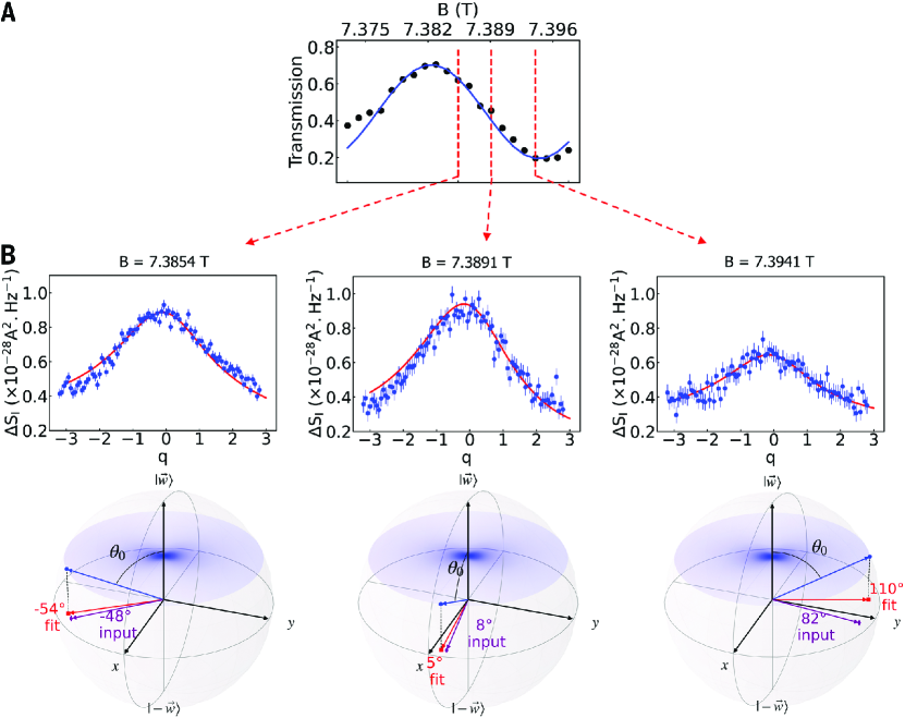
We first applied this operation to sine-shaped voltage pulses. The shot noise is essentially determined by the total number of electron-hole pairs created by the pulse multiplied by the factor . It is given by two-particle scattering processes that enclose the AB-flux once (leading to a phase contribution ) or two times () [see also “Floquet scattering formalism for graphene Mach-Zehnder interferometry” section in SI for the full formula]. Figure 4, C to F, shows the shot noise as a function of the magnetic field for several frequency values (), Investigated values verifies that the key property of Leviton, namely the minimization of the number of electron-hole pairs with 2e injected charges, is conserved while propagating in the MZI. Furthermore, the value of that is extracted from the amplitude of is consistent with that obtained from . These results demonstrate coherent control of Levitons.
Conclusions and Outlook Our study demonstrates the emission and coherent control of a quantum state at the single-electron level in monolayer graphene. Although graphene interferometers have been studied in the dc regime [10, 18, 19, 32, 33] sending on-demand excitations or flying qubits toward a MZI is a notable step toward quantum information transfer. We established an on-demand electron source in graphene based on Levitons that minimizes the number of unwanted electron-hole pairs. By sending periodically excited Levitons to the MZI, we demonstrated the rotation of the valley flying qubit on the Bloch sphere. Encoding quantum information in the valley state of Levitons should enable two-valley qubit operations to be considered [34, 35, 36, 37, 38]. There it can be shown that minimizing the number of electron-hole pairs is relevant against decoherence [see also “Levitons and decoherence” section in (SI]. These on-demand electron pulses can also carry fractional charges, which offers the possibility to braid anyons [39, 40, 41, 42, 43] in graphene in the time domain. Graphene is emerging as a promising material with robust quantum properties compared with those of conventional semiconductors. Beam splitters, interferometers, and single-electron sources can be easily realized using PN junctions, opening up avenues for electronic quantum optics experiments. Owing to the simple and elegant circuit topology that exploits N and P counter-propagating edge states, complex, yet compact, interferometers with original entanglement schemes can be envisioned.
Acknowledgments
We thank W. Dumnernpanich for his help with fabrication.
Funding: This work was funded by European Research Council (ERC) starting grant COHEGRAPH 679531 (P.R.); by European Metrology Programme for Innovation and Research (EMPIR) project SEQUOIA 17FUN04, which is cofinanced by the participating states and the European Union’s Horizon 2020 program (P.R.); by the National Research Foundation of Korea via the SRC Center for Quantum Coherence in Condensed Matter (grant no. 2016R1A5A1008184 and RS-2023-00207732) (H.-S.S.); and by “Investissements d’Avenir” LabEx PALM (ANR-10-LABX-0039-PALM) (Project ZerHall) (F.D.P.).
Author contributions: A.A., L.P., H.C., L.B., and P.R. performed the experiment with help from F.D.P.; A.A., L.P., H.C., L.B., N.K., S.L., H.-S.S., D.C.G., F.D.P., and P.R. analyzed and discussed the data; T.T. and K.W. provided the boron nitride layers; M.J. fabricated the device with input from A.A., F.D.P., and P.R.; P.R. wrote the manuscript with input from all co-authors; and P.R. designed and supervised the project. Competing interests: The authors declare no competing interests. Data and materials availability: Data and code are archived at Zenodo ( A. Assouline et al., Emission and coherent control of Levitons in graphene. Zenodo (2023); https://zenodo.org/records/ 10044265.)
References
- [1] C. Bäuerle et al. Coherent control of single electrons: A review. Reports on Progress in Physics, 81:056503, 2018.
- [2] Y. Ji et al. An electronic mach–zehnder interferometer. Nature, 422:415–418, 2003.
- [3] P. Roulleau et al. Direct measurement of the coherence length of edge states in the integer quantum hall regime. Physical Review Letters, 100:126802, 2008.
- [4] M. Yamamoto et al. Electrical control of a solid-state flying qubit. Nature Nanotechnology, 7:247–251, 2012.
- [5] E. Bocquillon et al. Coherence and indistinguishability of single electrons emitted by independent sources. Science, 339:1054–1057, 2013.
- [6] J. Dubois et al. Minimal-excitation states for electron quantum optics using levitons. Nature, 502:659–663, 2013.
- [7] D. C. Glattli and P. Roulleau. Levitons for electron quantum optics. Physica Status Solidi B: Basic Research, 254:1600650, 2017.
- [8] T. Jullien et al. Quantum tomography of an electron. Nature, 514:603–607, 2014.
- [9] D. Dasenbrook and C. Flindt. Dynamical detection of entanglement and squeezing in mesoscopic conductors. Physical Review B, 92:161412, 2015.
- [10] M. Jo et al. Observation of fractional statistics in the quantum hall regime. Physical Review Letters, 126:146803, 2021.
- [11] M. Jo et al. Observation of anyonic braiding statistics in quantum hall interferometers. Nature Communications, 13:5473, 2022.
- [12] J. R. Schaibley et al. Valleytronics in 2d materials. Nature Reviews Materials, 1:16055, 2016.
- [13] J. Park P. L. McEuen K. F. Mak, K. L. McGill. The valley hall effect in mos2 transistors. Science, 344:1489–1492, 2014.
- [14] Y. Shimazaki et al. Generation and detection of pure valley current by electrically induced berry curvature in bilayer graphene. Nature Physics, 11:1032–1036, 2015.
- [15] L. Ju et al. Topological valley transport at bilayer graphene domain walls. Nature, 520:650–655, 2015.
- [16] J. Li et al. Quantum hall effect in a gated two-dimensional electron gas. Science, 362:1149–1152, 2018.
- [17] R. V. Gorbachev et al. Detecting topological currents in graphene superlattices. Science, 346:448–451, 2014.
- [18] S. Morikawa et al. Tunable valley polarization and luminescence in bilayer graphene heterostructures. Applied Physics Letters, 106:183101, 2015.
- [19] D. S. Wei et al. Quantum-coherent nanocircuitry of graphene nanoribbons. Science Advances, 3:e1700600, 2017.
- [20] N. C. van der Vaart C. J. P. M. Harmans C. T. Foxon L. P. Kouwenhoven, A. T. Johnson. Quantized current in a quantum dot. Physical Review Letters, 67:1626–1629, 1991.
- [21] R. H. Rodriguez et al. Engineering topological quantum materials with twisted bilayers. Nature Communications, 11:2426, 2020.
- [22] M. Eich et al. Coupling spin and valley physics in two-dimensional systems. Physical Review X, 8:031023, 2018.
- [23] L. S. Levitov D. A. Ivanov, H. W. Lee. Coherent states of photons and electrons. Physical Review B, 56:6839–6850, 1997.
- [24] L. S. Levitov J. Keeling, I. Klich. Minimal excitation states of electrons in one-dimensional wires. Physical Review Letters, 97:116403, 2006.
- [25] C. Handschin et al. Electron quantum optics with ultrashort single-electron wave packets. Nano Letters, 17:5389–5393, 2017.
- [26] P. Makk et al. Tunable valley transport in mos2 systems. Physical Review B, 98:035413, 2018.
- [27] A. R. Akhmerov C. W. J. Beenakker J. Tworzydło, I. Snyman. Valley current generation in graphene junctions. Physical Review B, 76:035411, 2007.
- [28] P. W. Brouwer L. Trifunovic. Topological valleytronics in graphene nanostructures. Physical Review B, 99:205431, 2019.
- [29] D. C. Glattli B. Etienne Y. Jin L.-H. Reydellet, P. Roche. Electron quantum optics with levitons. Physical Review Letters, 90:176803, 2003.
- [30] M. Kapfer et al. Observing fractional statistics in electronic systems. Science, 363:846–849, 2019.
- [31] B. Reulet J. Gabelli. Shot noise in mesoscopic systems. Physical Review B, 87:075403, 2013.
- [32] C. Déprez et al. Coherent control of single-electron states in graphene systems. Nature Nanotechnology, 16:555–562, 2021.
- [33] Y. Ronen et al. Fractional quantum hall physics in graphene bilayers. Nature Nanotechnology, 16:563–569, 2021.
- [34] I. Neder et al. Quantum interference in the integer quantum hall effect. Nature, 448:333–337, 2007.
- [35] M. Büttiker P. Samuelsson, E. V. Sukhorukov. Quantum entanglement in mesoscopic conductors. Physical Review Letters, 92:026805, 2004.
- [36] N. Ubbelohde et al. Electron quantum optics in two-dimensional systems. Nature Nanotechnology, 18:733–740, 2023.
- [37] J. Wang et al. Coherent electron control in quantum nanocircuits. Nature Nanotechnology, 18:721–726, 2023.
- [38] J. D. Fletcher et al. Quantum optics with electron wave packets. Nature Nanotechnology, 18:727–732, 2023.
- [39] G. C. Gardner M. Manfra J. Nakamura, S. Liang. Fractional quantum hall states in a graphene bilayer. Nature Physics, 16:931–936, 2020.
- [40] H. Bartolomei et al. Fractional statistics in quantum hall states. Science, 368:173–177, 2020.
- [41] H.-S. Sim J. M. Lee, C. Han. Electron quantum optics with graphene systems. Physical Review Letters, 125:196802, 2020.
- [42] M. P. Röösli et al. Coherent control of levitons in graphene systems. Science Advances, 7:eabf5547, 2021.
- [43] J. M. Lee et al. Topological valley states in graphene. Nature, 617:277–281, 2023.
See pages - of Supply.pdf