Mechanism of generating collisionless shock in magnetized gas plasma driven by laser-ablated target plasma
Abstract
Mechanism of generating collisionless shock in magnetized gas plasma driven by laser-ablated target plasma is investigated by using one-dimensional full particle-in-cell simulation. The effect of finite injection time of target plasma, mimicking finite width of laser pulse, is taken into account. It was found that the formation of a seed-shock requires a precursor. The precursor is driven by gyrating ions, and its origin varies depending on the injection time of the target plasma. When the injection time is short, the target plasma entering the gas plasma creates a precursor, otherwise, gas ions reflected by the strong piston effect of the target plasma create a precursor. The precursor compresses the background gas plasma, and subsequently, a compressed seed-shock forms in the gas plasma. The parameter dependence on the formation process and propagation characteristics of the seed-shock was discussed. It was confirmed that the seed-shock propagates through the gas plasma exhibiting behavior similar to the shock front of supercritical shocks.
I Introduction
While collisionless shocks have long been studied as powerful accelerators of cosmic rays, their acceleration mechanisms remain highly complex and largely veiled. Studies of collisionless shocks have traditionally employed various methods such as in-situ and remote observations in space, theoretical modeling, and numerical simulations. Recently, in addition to these methods, efforts to generate magnetized collisionless shocks using high-power laser facilities in laboratory experiments have garnered significant attention Matsukiyo et al. (2022); Yamazaki et al. (2022); Yao et al. (2021); Schaeffer et al. (2019, 2017); Kuramitsu et al. (2016); Schaeffer et al. (2015, 2014); Niemann et al. (2014).
Among a number of methods of shock generation, Yamazaki et al. (2022)Yamazaki et al. (2022) and Matsukiyo et al. (2022)Matsukiyo et al. (2022) proposed a method to generate a shock in a homogeneously magnetized ambient gas plasma with uniform Alfvén velocity. In the experiment, a solid aluminum target irradiated with a laser is ablated and a surrounding nitrogen gas filling uniformly an entire chamber is ionized by the strong radiation emitted by the laser-target interaction. The ionized gas plasma initially at rest is uniformly magnetized in sufficiently large volume for a long time by using a Helmholtz-like coil. Although they observed developing shock (seed-shock hereafter), propagating in the gas plasma, detailed formation process of the seed-shock in this system has not been fully understood.
The complexity arises from the highly intricate interaction between gas plasma and target plasma. Since it is nearly impossible to separately measure the two plasmas in experiments, comparison with numerical simulations becomes crucial. However, there has not been a well-established computational method that accurately replicates these early-stage shock formations. One commonly used numerical simulation in this field is the Particle-in-Cell (PIC) simulation (Birdsall and Langdon, 2004). A number of methods of shock generation using the PIC simulation have been proposed so far (e.g. Pongkitiwanichakul et al., 2024; Zhang et al., 2021; Moreno et al., 2020; Schaeffer et al., 2020; Dieckmann et al., 2018 and reviewed in Ref. Burgess and Scholer, 2015). Normally, as enough time elapses, the influence of initial conditions and boundary conditions can be ignored, so differences in shock generation methods are not a concern. However, to accurately simulate the initial stages of shock generation observed in laser experiments, considerable attention needs to be paid to the initial setup of the calculations.
Fox et al. (2013)Fox et al. (2018) introduced a localized heating operator to refine and incorporate the effects of laser ablation. This involves setting up a high-density region mimicking the target at one end of the system (with a constant density over time) and imparting a sufficiently high plasma temperature only to that specific area. This allows the target plasma to thermally expand into its surroundings. In their approach, it is necessary to handle a very high-density plasma in a narrow region, which results in high computational costs. Matsukiyo et al. (2022)Matsukiyo et al. (2022) employed a different method to reproduce similar effects in one-dimensional simulations. They injected a high-temperature, high-density target plasma into a system filled with uniform background gas plasma at a specific point for a finite duration. This eliminates the need to deal with target material that does not interact with the background gas plasma, thereby reducing computational costs. In the simulation they showed that injected target ions gyrate around ambient magnetic field in a gas plasma and turned back after a quarter of their gyro period. During this, a background gas ions are dragged (or accelerated) by the target ions so that the gas ions are gradually accumulated and compressed to form a shock-like steepened density profile afterwards. They called this steepened structure a developing shock. However, it is unclear how universal the process is. If the mechanism for generating a shock in experiments is elucidated, it would enable us to devise means to generate a shock in a short period of time, making it possible to measure a more developed shock.
In this paper we use the same simulation method as Ref. Matsukiyo et al., 2022 to investigate the mechanism of shock formation in a magnetized gas plasma interacting with an ablated target plasma. We will show that the mechanism of shock formation changes depending on the injection time of target plasma. Moreover, it will be demonstrated that the time it takes to form a sufficiently steep density structure depends on the strength of the ambient magnetic field. To distinguish the structure we mainly discuss in this paper with usually discussed a well developed shock, we call the early stage steepened density or magnetic field structure discussed here a seed-shock, which does not accompany well developed steady and long enough downstream state. A seed-shock is equivalent to the structure named a developing shock in Ref. Matsukiyo et al., 2022.
II Simulation settings
We perform one-dimensional full particle-in-cell simulations using the same simulation code as in Ref. Matsukiyo et al., 2022. Initially a thermal gas plasma consisting of electrons and ions is uniformly distributed in the system (). The valence of gas ions is assumed to be throughout this study. The ambient magnetic field is applied in direction. The velocity distribution function is Maxwellian for both electrons and ions. In most of the following runs, , where is the speed of light and denotes ion plasma frequency. The number of spatial grids is , and the number of particles per cell is 256 for each species. We postulate that a target plasma is created for a finite period of time with a constant rate. If a solid target is thick enough, the created target electrons may have a half-Maxwellian distribution function in which there are no electrons having negative velocity in . The target ions, on the other hand, may have a bulk velocity, , to compensate the current produced by the half-Maxwellian electrons. With this assumption, the temperature of the target electrons can be written as . We further assume that the temperature of target ions is the same as the electrons, , and ion distribution function is shifted-Maxwellian. The target plasma is injected at during . It carries the magnetic field generated through the laser-target interaction, which dynamically changes based on the motion of the target plasma. In experiment, this magnetic field, known as the Biermann battery field (Stamper et al., 1971; Stamper, McLean, and Ripin, 1978; Yates et al., 1982), is generated in a ring-like shape around the laser spot on the target surface and expands over time along with the target plasma. In this one-dimensional simulation we assume that the direction of this magnetic field is in direction. One of the objectives of this paper is to elucidate the effects of finite injection time of target plasma in the generation of a shock in a gas plasma. This is equivalent to accounting for the effects of finite laser irradiation time in experiments (Note that total laser power is proportional to .).
In Runs 1-6, for the gas plasma, the ion-to-electron mass ratio is , the ratio of electron cyclotron frequency to plasma frequency , the electron and ion betas , respectively. For the target plasma, the valence of ions is , and the ion-to-electron mass ratio . The density ratio of target electrons to gas electrons is and the magnetic field carried by the target plasma is 6 times the ambient field (). The mass ratio of target ions to gas ions is which is close to that of aluminum (target) to nitrogen (gas) (). In the subsequent sections, calculated values are presented in both normalized and unit-attached forms. Normalization is based on the scale of gas ions, i.e., time is to inverse ion gyro frequency, , velocity is to Alfvén velocity, , and space is to ion inertial length, , respectively. When converting to values with units attached, typical values from the Gekko XII experiment are used as normalization constants for these ions. Since we have used unrealistic ion-to-electron mass ratio, electron dynamics such as gyro motion and Debye shielding have relatively larger scale lengths. However, they are still much smaller than ions’ so that electron scale phenomena in the simulation here may not affect significantly in ion dynamics. We will confirm this later. It should also be noted that in Ref. Matsukiyo et al., 2022, the same simulation code as well as the similar parameters used here were employed, and the results were found to be in good agreement with the experimental data discussed in it.
The injection speed of target ions using the Gekko XII experiment at the Institute of Laser Engineering in Osaka University is typically a little less than 1,000 km/s for the laser intensity of . Here, we assume that the injection speed is 850 km/s. In Runs 1-3, we assume that , where denotes the Alfvén velocity in the gas plasma. This corresponds to the case of the ambient magnetic field strength being 4.4 T for nitrogen ions, . In Runs 4-6, on the other hand, is assumed, corresponding to the case with 6 T ambient magnetic field and the same ion density. For the both cases, five different values of are used. The above values are summarized in Table 1.
| 0.65 [ns] | 1.3 [ns] | 2.6 [ns] | 3.9 [ns] | 5.2 [ns] | |
|---|---|---|---|---|---|
| 4.4 [T] | Run 1 | Run 2 | Run 3 | ||
| (1.92E-2) | (3.92E-2) | (7.83E-2) | (1.17E-1) | (1.57E-1) | |
| (5.87E-2) | (1.17E-1) | (2.35E-1) | (3.52E-1) | (4.70E-1) | |
| 6.0 [T] | Run 4 | Run 5 | Run 6 | ||
| (2.67E-2) | (5.34E-2) | (1.07E-1) | (1.60E-1) | (2.14E-1) | |
| (8.01E-2) | (1.60E-1) | (3.20E-1) | (4.81E-1) | (6.41E-1) |
III Mechanism of shock formation
III.1 Spatio-temporal evolution of density
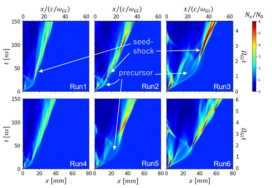
Fig.1 shows the spatio-temporal evolution of electron density for Runs 1-6. In each case the red colored high density structure initially occurs near and propagates while forming an arc in the space. In front of it, a complex light blue or yellow-green structure, hereafter we call it a precursor, is formed. When it turns around, another red (or yellow for Run 4) colored compressed structure appears and propagates forward. Here, we define a precursor as the structure arching out into upstream, observed just before the compressed structure propagating forward begins to grow.
As will be discussed later, the compressed structure propagating forward grows to become a shock in each case. Therefore, we will refer to this structure as a seed-shock. The approximate time when a seed-shock first becomes visible for T is around 30 ns in Runs 1 and 2, while it is around 60 ns in Run 3. Similarly, the corresponding time for T is around 20 ns in Run 4, while it is around 50 ns or less in Runs 5 and 6. There is a big jump between Run 2 and Run 3 (Run 4 and Run 5), implying that the mechanism of shock formation changes here. From Table I, the change may occur at (, where is target ion gyro frequency).
III.2 Seed-shock formation: Run 2
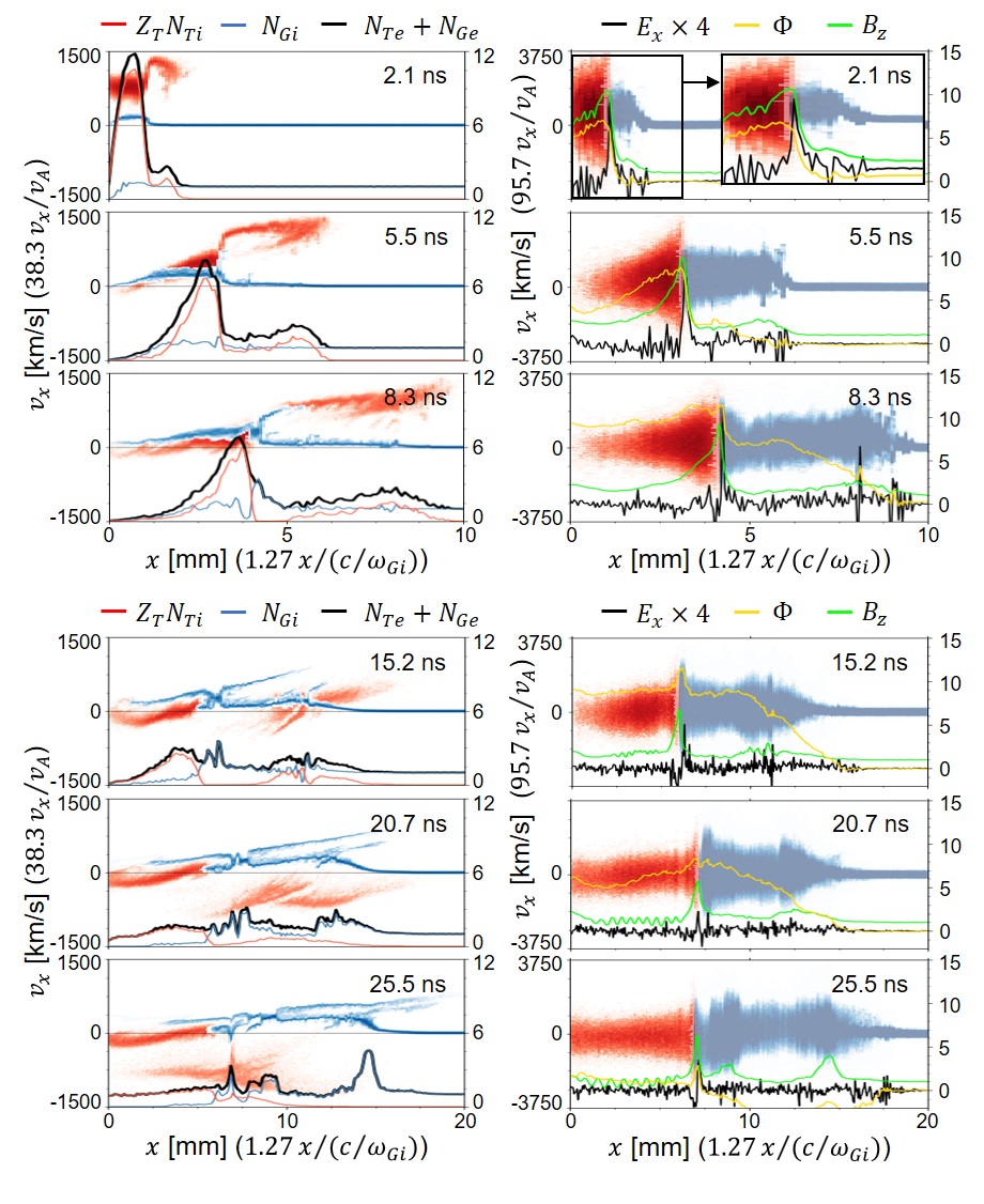
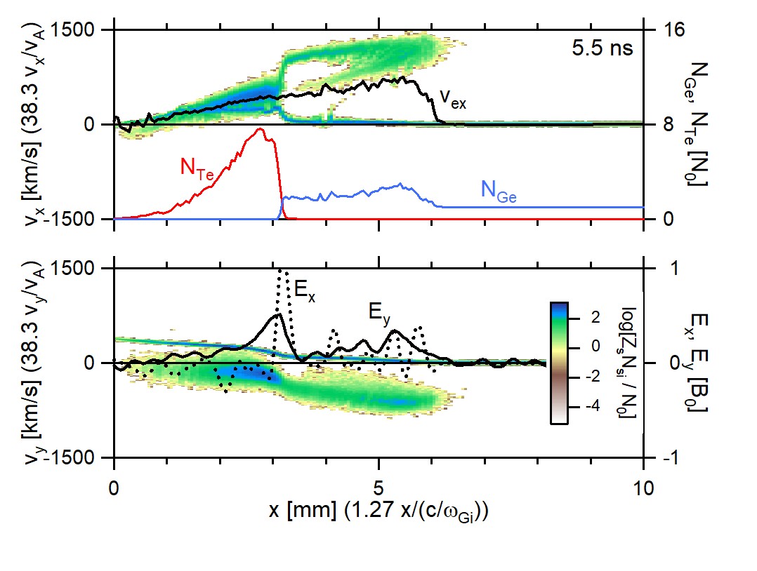
Fig.2 denotes the evolution of phase space and field profiles in the early stage of Run 2. In each time, the left panel shows the phase space density of target (gas) ions in reddish (bluish) color scale, and the ion density profiles of target and gas ions are denoted by red and blue lines, where the target ion density is multiplied by the valence of ions. The total electron density is indicated by black solid line. In the right panel, the phase space density of target (gas) electrons are denoted by reddish (bluish) color scale, while the green, black, and yellow lines indicate the profiles of , , and potential , respectively. As time passes, the gas plasma is pushed by the target plasma so that a majority of injected target ions are decelerated and the gas ions are accelerated ( ns). Therefore, more ions are accumulated near the interface. Fig.3 provides a more detailed view of this situation at ns. The upper panel shows the phase space distribution of ions’ charge density in color scale, the bulk velocity of the electrons in the direction () with a black line, and the densities of the target electrons () and gas electrons () with red and blue lines, respectively. The target and gas electrons are spatially well separated, as they are tied with magnetic field lines of each origin. In the lower panel, the ion’s phase space distribution is shown in color scale, and the and components of the electric field are represented by a black dotted line and a solid black line, respectively. The magnetized incident target plasma carries a convective electric field (), which accelerates the gas plasma in the direction while the magnetic field causes it to gain velocity in the direction (the motion). The motion of gas ions corresponding to this process can be observed in the region mm in the figure. At the same time, the target ions decelerate due to the reaction force. As a result, ions gradually accumulate in this boundary region, forming a potential maximum (Fig.2). To the left of this maximum ( mm), the spatial gradient of the potential becomes positive, leading to a negative , which also contributes to the deceleration of the incoming target ions. Conversely, to the right of the potential maximum ( mm), a positive is generated due to the negative spatial gradient of the potential. Some of the target ions that enter this region are accelerated by this . In response to the direction current generated by the accelerated target ions, the gas electrons are accelerated in the direction (refer to the black line () in the upper panel of Fig.3). The bulk velocity of these electrons induces an electric field in the direction through Ohm’s law, with (see the lower panel of Fig.3 for mm). This accelerates the gas ions in the direction, causing them to gain velocity in the direction through the magnetic field ( motion). The above describes the initial interaction between the target plasma and the gas plasma. If we define the region occupied by the gas electrons as the gas plasma region (in ns, this is the region mm), the gyro motion of the target ions that enter the gas plasma region is observed as the precursor in Fig.1. After the gyrating target ions reverse their direction ( ns in Fig.2), the accelerated gas ions gradually accumulate forward, leading to the steepening of density as well as magnetic field and the growth of the seed of a shock front ( ns), which is a seed-shock. The formation mechanism of a seed-shock in Runs 1 and 4 is qualitatively the same as in Run 2.
III.3 Seed-shock formation: Run 3
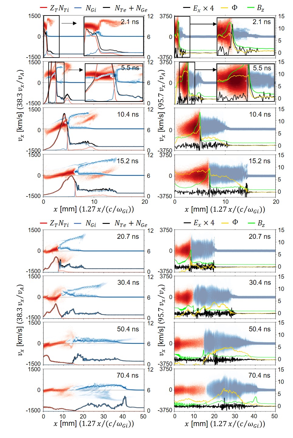
Fig.4 depicts the same plot as Fig.2 but for Run 3. While the initial behaviors of target plasma and gas plasma are similar to what are observed in Run 2 (Fig.2), more gas plasma is compressed and accelerated in the initial stage ( ns). Since the target plasma is injected with the laser-generated magnetic field, both the flux of the injected target plasma and the magnetic flux it carries are proportional to the injection time. When the injection time is short, the target plasma disperses spatially due to velocity dispersion, which reduces the magnetic flux density carried by the target plasma, and the piston effect weakens rapidly (Run 2). On the other hand, if the injection time is sufficiently long, the target plasma with a constant magnetic flux density compresses the gas plasma for an extended period, resulting in a strong piston effect, and more gas ions are reflected by the magnetic piston (Run 3). Therefore, more gas ions are reflected by the magnetic piston. This can be observed in ns. As a result, despite the accelerated target ions moving forward at a faster velocity than the reflected gas ions, their impact on the background gas ions has become relatively weaker compared to the case of Run 2. After the target ions move downstream through gyro-motion, the reflected gas ions form a precursor ( ns), accelerating background gas ions ( ns) and creating the seed for a shock further ahead ( ns). The seed-shock formation mechanism in Runs 5 and 6 is qualitatively the same as in Run 3.
IV Parameter dependence of seed-shock properties
IV.1 Dependence on and
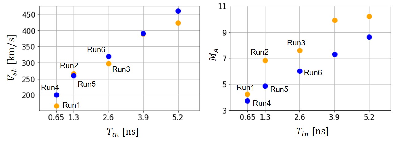
The Alfvén Mach number () and propagation velocity () of generated seed-shock is plotted as a function of in Fig.5. The velocity of a seed-shock is calculated as the peak-to-peak (from the first peak to the second peak) velocity of the electron density of a reforming seed-shock (Fig.1). In the figure, in addition to the Runs 1-6, the results for ns and 5.2 ns are also plotted. As increases, both and of the seed-shock increase significantly. This is attributed to the suppression of target plasma deceleration by injecting target plasma for an extended duration, thereby maintaining a strong magnetic piston effect. It is noteworthy that a higher external magnetic field () leads to similar or a little higher , but decreases. However, in all runs, , indicating that the seed-shocks are supercritical Tidman and Krall (1971).
In Fig.1, the high-density structure corresponding to the seed-shock exhibits periodic temporal variations. The periods of these variations are around 50-60 ns in Runs 1-3 and a little shorter than 50 ns in Runs 4-6. These values correspond to about one-quarter of the gyro period of gas ions in each run. Between the peaks of density maxima, there is a region where the density slightly increases, protruding forward. This region constitutes the foot region occupied by gas ions reflected by the seed-shock. These features are essentially the same as those of shock reformation Biskamp and Welter (1972); Lembege and Dawson (1987); Lembege and Savoini (1992), confirming that the seed-shock behaves similarly to the shock front of a supercritical shock.
IV.2 Other parameter dependence
| Run # | 3 | 3A | 3B | 3C | 3D | 3E | 6 |
|---|---|---|---|---|---|---|---|
| 100 | 50 | 200 | - | - | - | - | |
| 0.05 | - | - | - | - | - | 0.068 | |
| 6 | - | - | 3 | 12 | - | - | |
| 7 | - | - | - | - | 14 | - |
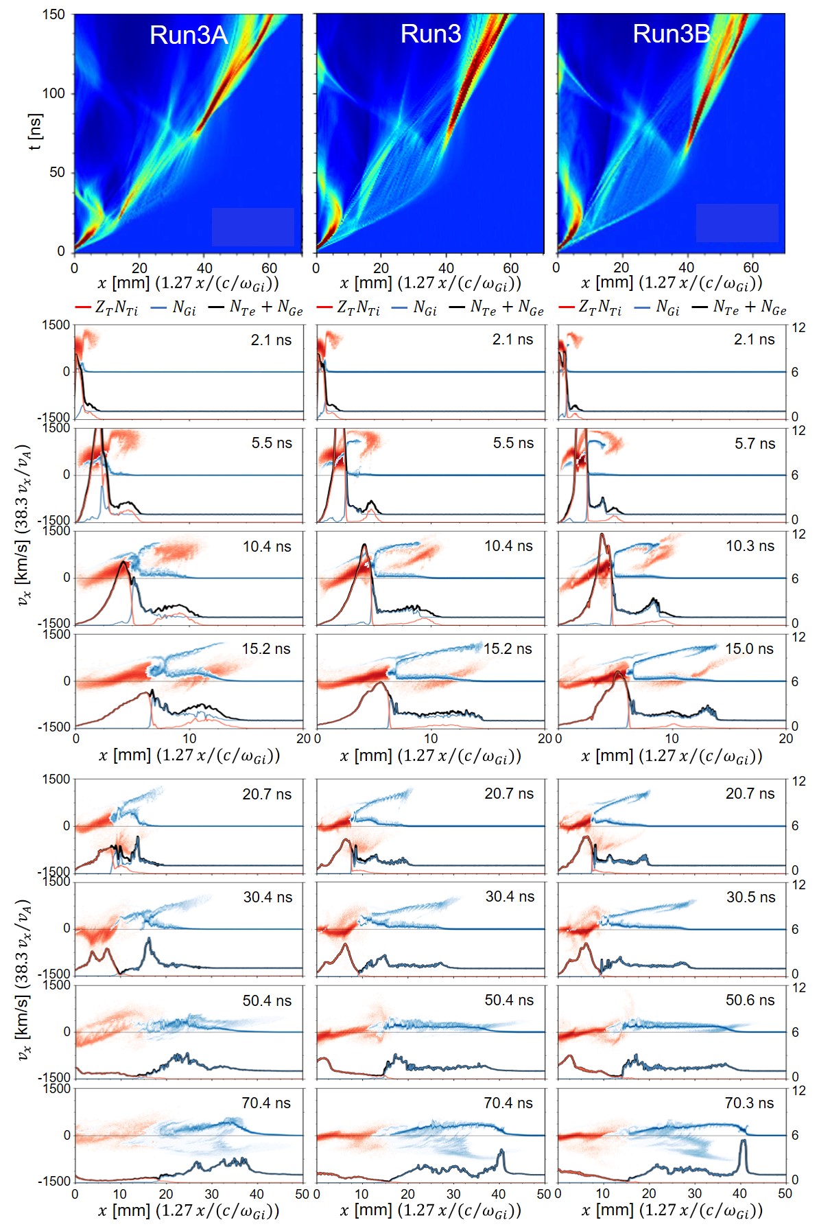
Other parameter dependence is discussed here, with Run 3 as a reference. The parameters changed from Run 3 are summarized in Table 2. First, let us discuss the dependence on the ion to electron mass ratio. In Run 3, the mass ratio of the gas plasma was set to 100. Here, this value is changed to 50 (Run 3A) and 200 (Run 3B). However, the mass ratio of target ions to gas ions is kept fixed at 2 during this adjustment. Fig.6 shows the spatio-temporal evolution of electron density and the time evolution of ion phase space and charge density profiles for each run. In all three runs, it is common for the precursor of reflected gas ions to eventually create the seed-shock. However, the relative density of target ions entering the gas plasma region in the early stages ( ns) becomes larger as the mass ratio decreases. This is due to normalizing particle velocities with the Alfvén speed. As the mass ratio decreases and the Alfvén speed increases, the thermal velocity of target ions also increases. As a result, ions with higher velocities enter the gas plasma region more frequently. In Runs 3 and 3B, the influence of target ions is suppressed, and the development of the system appears quite similar.
A similar behavior is observed when we change the ratio of electron cyclotron frequency to plasma frequency () with other parameters being fixed. Increasing the frequency ratio results in a higher Alfvén speed, and consequently, the thermal velocity of target ions increases, leading to more target ions entering the gas plasma region.
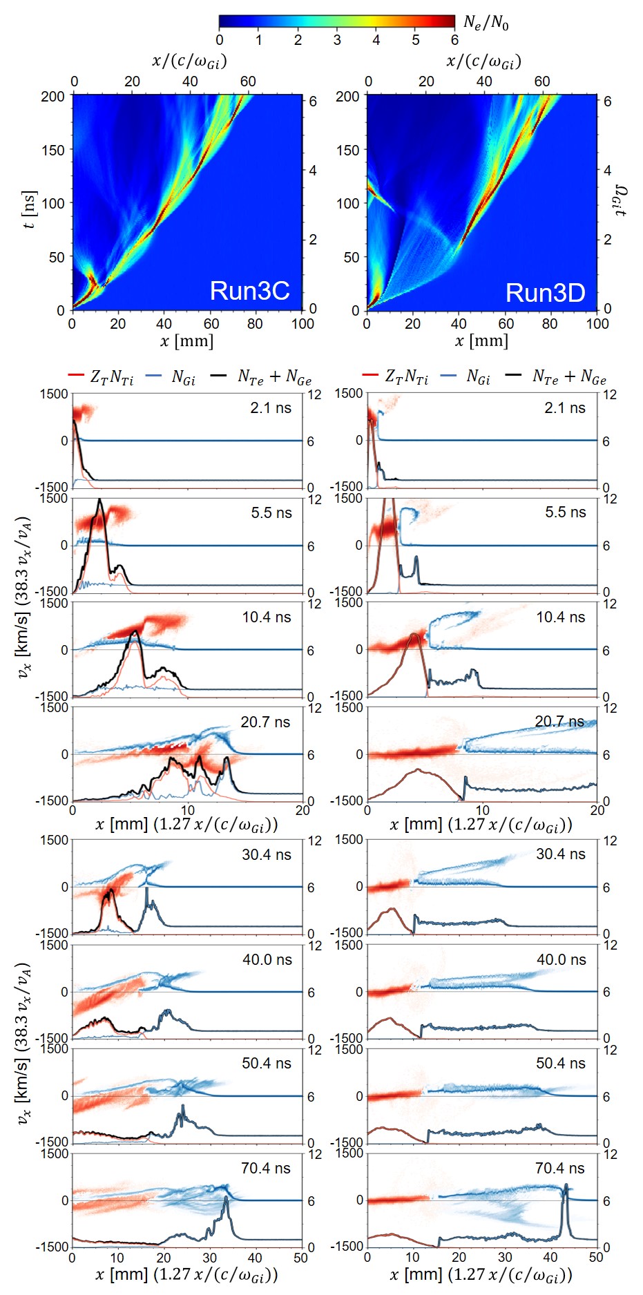
The mechanism for seed-shock generation also varies depending on the relative strength of magnetic field carried by the target plasma. Fig.7 presents the results of calculations where the ratio of electron cyclotron frequencies between the target plasma and the gas plasma () is altered. In the case of low (Run 3C: ), more target ions enter the gas plasma to form the precursor. On the other hand, in the case of high (Run 3D: ), target ions do not penetrate the gas plasma region significantly. Instead, efficient reflection of gas ions contributes to the formation of the precursor. The propagation speed of seed-shock is faster in Run 3D.
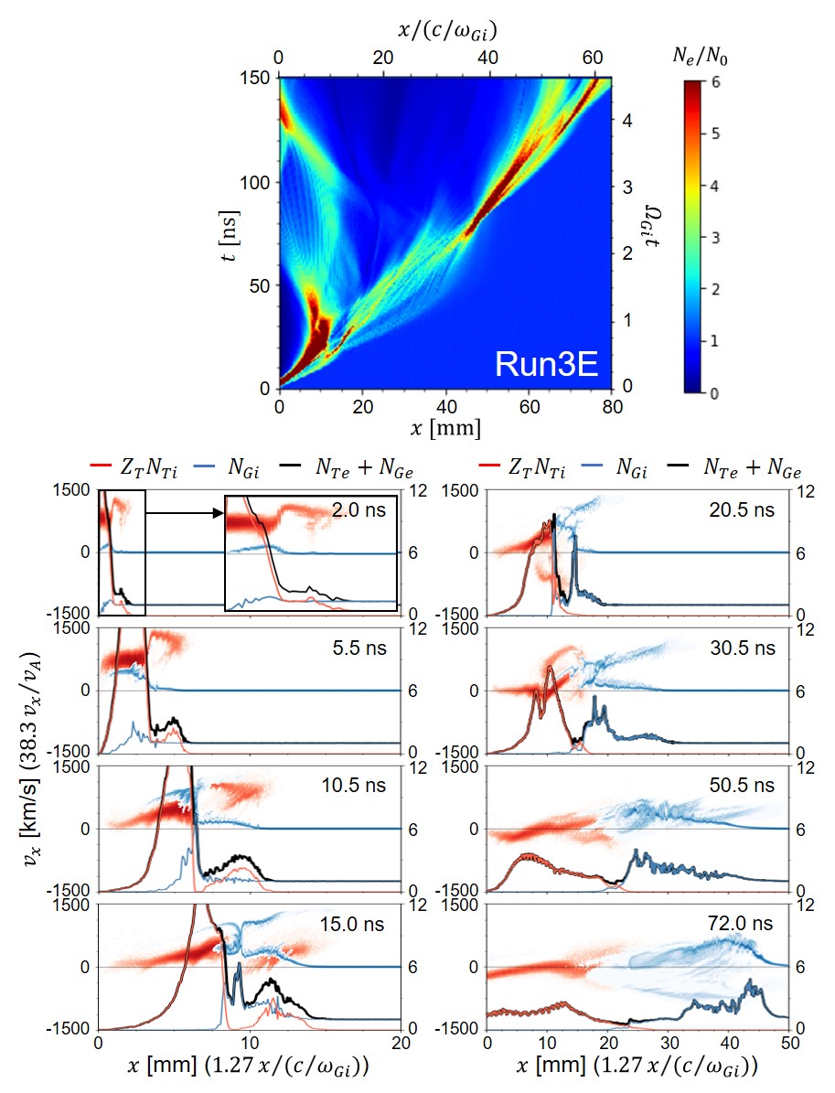
When we keep constant and increasing the relative density of the target plasma (Run 3E: ), it was observed that the piston effect by the target enhances and that the density of target ions entering the gas plasma region increases. Fig.8 depicts the space-time plot of electron density and the temporal evolution of ion phase space and charge density profiles. In the space-time plot, the propagation speed of the seed-shock is higher compared to Run 3 (Fig.1), indicating the strengthening of the piston effect from the target. Observing the temporal evolution of ion phase space and charge density profiles, the precursor by target ions has developed until ns due to the high density of target ions entering the gas plasma region. Simultaneously, at the boundary of the two plasmas, some gas ions are reflected, and the precursor originating from reflected gas ions grows, eventually surpassing the precursor from target ions ( ns). Ultimately, it grows into the seed-shock. Increasing the density ratio is expected to further enhance the precursor from target ions, contributing to the formation of the seed-shock.
V Discussions
Up to this point, it has been established that the generation of the seed-shock requires a precursor, and there are precursors originating from target ions and reflected gas ions. It is understood that if a sufficient number of target ions enter the gas plasma region, they form the precursor, and for this, conditions such as a high relative density and low magnetization of the target plasma are suitable. Under the opposite conditions, reflected gas ions form the precursor. The actual experiment needs consideration of which condition is closer.
The ion-to-electron mass ratio and the ratio of electron cyclotron frequency to plasma frequency are both unrealistic in the simulations, leading to an overestimation of the Alfvén speed, a constant for velocity normalization. Consequently, the thermal velocity of target ions increases, resulting in an excessive influx of target ions into the gas plasma region. Therefore, bringing these values closer to experimental values would likely make it easier for the precursor from reflected gas ions to form.
On the other hand, the relative density and magnetization of the target plasma are expected to vary significantly in the three-dimensional spatiotemporal evolution of the system. The ion density of the target plasma immediately after laser irradiation is close to solid density, approximately for an aluminum target. The magnetic field generated on the target surface by the laser, known as the Biermann battery field, is around 100T Sutcliffe et al. (2022); Umeda et al. (2019). The calculated magnetization of the target plasma from these values is on the order of . This is much smaller than the simulations here, implying that some target ions easily enter the gas plasma region. Assuming an initial velocity of target ions to be around 1000 km/s, the gyro radius in a 100T magnetic field is on the order of 0.1-1 mm, depending on the valence of ions. This is roughly equivalent to the spot size of the irradiating laser. From these considerations, it is natural to assume that at least some target ions immediately after laser irradiation propagate through the gas plasma without sufficient magnetization.
In Ref. Matsukiyo et al., 2022, a precursor was observed up to about 20mm from the target in an external magnetic field of 3.8T. If we attempt to explain this by considering the gyro radius of target (aluminum) ions, the initial velocity of target ions must be around 280 km/s. Yamazaki et al. (2022)Yamazaki et al. (2022) estimated the head speed of an aluminum target to be approximately 800 km/s, making it a reasonable value for . On the other hand, if we try to explain this using the gyro radius of reflected nitrogen gas ions, the initial velocity of reflected ions must be around 540 km/s. For example, the propagation velocity of the initial magnetic piston in Run 2 (up to 2.1 ns) is approximately 500 km/s. Assuming a similar velocity in the experiment, the speed of the gas ions reflected by the magnetic piston would be around 1,000 km/s, so 540 km/s () would be too small as the velocity of nitrogen ions when reflected by the initial magnetic piston. Values such as 1040 km/s () or 1620 km/s () would be more plausible. In other words, to identify the origin of the precursor observed in the experiment in Ref. Matsukiyo et al., 2022, additional data and analysis are required.
We also propose another experimental design to clarify the origin of the precursor. Since the precursor reflects the gyro-motion of target ions or reflected gas ions, identifying the origin of the precursor should be possible by separating the spatiotemporal scales of both. Choosing light gas species with a small atomic mass is preferable for this purpose, and hydrogen gas is an ideal candidate. Hydrogen is known to ionize into singly charged ions, making it easier to estimate gyro radii and gyro periods. Yao et al. (2021)Yao et al. (2021) conducted experiments on magnetized plasma shock waves using hydrogen gas and CF2 as the target, but they did not specifically focus on the initial stages of the system’s temporal evolution. Helium, being capable of ionizing into singly or doubly charged ions, also provides an easily estimable scale for gyro-motion.
In this study, the effects of particle collisions have been neglected. The velocity of the ablation plasma (target ions) immediately after the shot in the Gekko XII experiment is estimated to be a little smaller than 1000 km/s. Using this value to estimate the Coulomb collision mean free path between a target aluminum ion entering the gas and the nitrogen gas ions, assuming a gas pressure of 5 Torr, the mean free path is larger than the size of the Gekko XII device. Similarly, the mean free path between the background ions and reflected ions in the gas is also larger than the size of the experimental region (a few cubic centimeters), indicating that ion-ion interactions can be treated as collisionless. On the other hand, the effect of electron collisions cannot be ignored. For example, referring to the calculation results here, if the electron temperature near the interface between the target and the gas plasmas is more than ten times ( eV) that of the upstream gas electrons, the mean free path between the electrons and nitrogen ions in the gas is on the order of mm when the valence of ions is , and mm when the valence of ions is . This is comparable to the electron inertial length. However, the electron gyroradius is smaller, around mm (assuming a magnetic field of 5 T), so the gas electrons are magnetized (The Hall parameter Lancia et al. (2014) exceeds unity.). Regarding the target electrons, it has been reported that the target electrons expanding in vacuum are either unmagnetized or weakly magnetized, except near the target surface Lancia et al. (2014). Therefore, the validity of the model used in this study, which assumes the injection of magnetized target plasma, requires further investigation. Note also that in Lancia et al., 2014, the laser spot size was 100 microns, which is an order of magnitude smaller than the value in the Gekko XII experiment, and the effects of the ambient gas were not considered, so careful verification is required to determine whether this applies to the current situation. Based on the above, the fundamental picture presented in this paper seems likely to occur in actual experiments as well. However, for quantitative discussions and phenomena where electron dynamics become significant, further investigation will be necessary, such as conducting calculations that explicitly incorporate collisional effects.
Lastly, We would like to address the multidimensional effects. The 1D assumptions adopted in this study are quite strong. As mentioned earlier, in the experiment, the target plasma expands in three dimensions. In this study, we fixed the direction of the laser-generated magnetic field to the direction, but in reality, the laser-generated magnetic field also has a three-dimensional structure. If we consider the boundary between the target plasma and the gas plasma as a multi-fluid plasma, various plasma instabilities could be excited. However, a 1D calculation may not accurately reproduce these instabilities. We recognize that multidimensional effects are a subject that should be carefully discussed in the future.
Acknowledgements.
This research was supported by the JSPS KAKENHI Grant no 22H01287, 23K22558 (SM), 22H01251, 23H01211, 23H04899, 23K22522 (RY), 20KK0064 (YK), and 22H00119 (YS).Data Availability Statement
The data that support the findings of this study are available from the corresponding author upon reasonable request.
References
- Matsukiyo et al. (2022) S. Matsukiyo, R. Yamazaki, T. Morita, K. Tomita, Y. Kuramitsu, T. Sano, S. J. Tanaka, T. Takezaki, S. Isayama, T. Higuchi, H. Murakami, Y. Horie, N. Katsuki, R. Hatsuyama, M. Edamoto, H. Nishioka, M. Takagi, T. Kojima, S. Tomita, N. Ishizaka, S. Kakuchi, S. Sei, K. Sugiyama, K. Aihara, S. Kambayashi, M. Ota, S. Egashira, T. Izumi, T. Minami, Y. Nakagawa, K. Sakai, M. Iwamoto, N. Ozaki, and Y. Sakawa, Phys. Rev. E 106, 025205 (2022).
- Yamazaki et al. (2022) R. Yamazaki, S. Matsukiyo, T. Morita, S. J. Tanaka, T. Umeda, K. Aihara, M. Edamoto, S. Egashira, R. Hatsuyama, T. Higuchi, T. Hihara, Y. Horie, M. Hoshino, A. Ishii, N. Ishizaka, Y. Itadani, T. Izumi, S. Kambayashi, S. Kakuchi, N. Katsuki, R. Kawamura, Y. Kawamura, S. K. T. Kojima, A. Konuma, R. Kumar, T. Minami, I. Miyata, T. Moritaka, Y. Murakami, K. Nagashima, Y. Nakagawa, T. Nishimoto, Y. Nishioka, Y. Ohira, N. Ohnishi, M. Ota, N. Ozaki, T. Sano, K. Sakai, S. Sei, J. Shiota, Y. Shoji, K. Sugiyama, D. Suzuki, M. Takagi, H. Toda, S. Tomita, S. Tomiya, H. Yoneda, T. Takezaki, K. Tomita, Y. Kuramitsu, and Y. Sakawa, Phys. Rev. E 105, 025203 (2022).
- Yao et al. (2021) W. Yao, A. Fazzini, S. N. Chen, K. Burdonov, P. Antici, J. Beard, S. Bolanos, A. Ciardi, R. Diab, E. D. Filippov, S. Kisyov, V. Lelasseux, M. Miceli, Q. Moreno, V. Nastasa, S. Orlando, S. Pikuz, D. C. Popescu, G. R. X. Ribeyre, E. d’Humieres, and J. Fuchs, Nature Phys. 17, 1177 (2021).
- Schaeffer et al. (2019) D. B. Schaeffer, W. Fox, R. K. Follett, G. Fiksel, C. K. Li, J. Matteucci, A. Bhattacharjee, and K. Germaschewski, Phys. Rev. Lett. 122, 245001 (2019).
- Schaeffer et al. (2017) D. B. Schaeffer, W. Fox, D. Haberberger, G. Fiksel, A. Bhattacharjee, D. H. Barnak, S. T. Hu, and K. Germaschewski, Phys. Rev. Lett. 119, 025001 (2017).
- Kuramitsu et al. (2016) Y. Kuramitsu, N. Ohnishi, Y. Sakawa, T. Morita, H. Tanji, T. Ide, K. Nishio, C. D. Gregory, J. N. Waugh, N. Booth, R. Heathcote, C. Murphy, G. Gregori, J. Smallcombe, C. Barton, A. Diziere, M. Koenig, N. Woolsey, Y. Matsumoto, A. Mizuta, T. Sugiyama, S. Matsukiyo, T. Moritaka, T. Sano, and H. Takabe, Phys. Plasmas 23, 032126 (2016).
- Schaeffer et al. (2015) D. B. Schaeffer, E. T. Everson, A. S. Bondarenko, S. E. Clark, and C. G. Constantin, Phys. Plasmas 22, 113101 (2015).
- Schaeffer et al. (2014) D. B. Schaeffer, E. T. Everson, A. S. Bondarenko, S. E. Clark, C. G. Constantin, S. Vincena, B. V. Compernolle, S. K. P. Tripathi, D. Winske, W. Gekelman, and C. Niemann, Phys. Plasmas 21, 056312 (2014).
- Niemann et al. (2014) C. Niemann, W. Gekelman, C. G. Constantin, E. T. Ev-erson, D. B. Schaeffer, A. S. Bondarenko, S. E. Clark, D. Winske, S. Vincena, B. V. Compernolle, and P. Pribyl, Geophys. Res. Lett. 41, 7413 (2014).
- Birdsall and Langdon (2004) C. K. Birdsall and A. B. Langdon, Plasma Physics via Computer Simulation (Taylor and Francis, 2004).
- Pongkitiwanichakul et al. (2024) P. Pongkitiwanichakul, D. B. Schaeffer, W. F. andD. Ruffolo, J. Donaghy, and K. Germaschewski, Phys. Plasmas 31, 012901 (2024).
- Zhang et al. (2021) Y. Zhang, J. R. Davies, P. V. Heuer, and C. Ren, Phys. Plasmas 28, 072111 (2021).
- Moreno et al. (2020) Q. Moreno, A. Araudo, P. Korneev, C. K. Li, V. T. Tikhonchuk, X. Ribeyre, E. d’Humières, and S. Weber, Phys. Plasmas 27, 122106 (2020).
- Schaeffer et al. (2020) D. B. Schaeffer, W. Fox, J. Matteucci, K. V. Lezhnin, A. Bhattacharjee, and K. Germaschewski, Phys. Plasmas 27, 042901 (2020).
- Dieckmann et al. (2018) M. E. Dieckmann, Q. Moreno, D. Doria, L. Romagnani, G. Sarri, D. Folini, R. Walder, A. Bret, E. d’Humières, and M. Borghesi, Phys. Plasmas 25, 052108 (2018).
- Burgess and Scholer (2015) D. Burgess and M. Scholer, Collisionless Shocks in Space Plasmas (Cambridge University Press, 2015).
- Fox et al. (2018) W. Fox, J. Matteucci, C. Moissard, D. B. Schaeffer, A. Bhattacharjee, K. Germaschewski, and S. X. Hu, Phys. Plasmas 25, 102106 (2018).
- Stamper et al. (1971) J. A. Stamper, K. Papadopoulos, R. N. Sudan, S. O. Dean, and E. A. McLean, Phys. Rev. Lett. 26, 1012 (1971).
- Stamper, McLean, and Ripin (1978) J. A. Stamper, E. A. McLean, and B. H. Ripin, Phys. Rev. Lett. 40, 1177 (1978).
- Yates et al. (1982) M. A. Yates, D. B. van Hulsteyn, H. Rutkowski, G. Kyrala, and J. U. Brackbill, Phys. Rev. Lett. 49, 1702 (1982).
- Tidman and Krall (1971) D. A. Tidman and N. A. Krall, Shock Waves in Collisionless Plasmas (New York: Wiley-Interscience, 1971).
- Biskamp and Welter (1972) D. Biskamp and H. Welter, Nucl. Fusion 12, 663 (1972).
- Lembege and Dawson (1987) B. Lembege and J. M. Dawson, Phys. Fluids 30, 1767 (1987).
- Lembege and Savoini (1992) B. Lembege and P. Savoini, Phys. Fluids B 4, 3533 (1992).
- Sutcliffe et al. (2022) G. D. Sutcliffe, J. A. Pearcy, T. M. Johnson, P. J. Adrian, N. V. Kabadi, B. Pollock, J. D. Moody, R. D. Petrasso, and C. K. Li, Phys. Rev. E 105, L063202 (2022).
- Umeda et al. (2019) T. Umeda, R. Yamazaki, Y. Ohira, N. Ishizaka, S. Kakuchi, Y. Kuramitsu, S. Matsukiyo, I. Miyata, T. Morita, Y. Sakawa, T. Sano, S. Sei, S. J. Tanaka, H. Toda, and S. Tomita, Phys. Plasmas 26, 032303 (2019).
- Lancia et al. (2014) L. Lancia, B. Albertazzi, C. Boniface, A. Grisollet, R. Riquier, F. Chaland, K.-C. L. Thanh, P. Mellor, P. Antici, S. Buffechoux, S. N. Chen, D. Doria, M. Nakatsutsumi, C. Peth, M. Swantusch, M. Stardubtsev, L. Palumbo, M. Borghesi, O. Willi, H. Pépin, and J. Fuchs, Phys. Rev. Lett. 113, 235001 (2014).