A Cranial-Feature-Based Registration Scheme for Robotic Micromanipulation Using a Microscopic Stereo Camera System
Abstract
Biological specimens exhibit significant variations in size and shape, challenging autonomous robotic manipulation. We focus on the mouse skull window creation task to illustrate these challenges. The study introduces a microscopic stereo camera system (MSCS) enhanced by the linear model for depth perception. Alongside this, a precise registration scheme is developed for the partially exposed mouse cranial surface, employing a CNN-based constrained and colorized registration strategy. These methods are integrated with the MSCS for robotic micromanipulation tasks. The MSCS demonstrated a high precision of 0.10 mm ± 0.02 mm measured in a step height experiment and real-time performance of 30 FPS in 3D reconstruction. The registration scheme proved its precision, with a translational error of 1.13 mm ± 0.31 mm and a rotational error of 3.38° ± 0.89° tested on 105 continuous frames with an average speed of 1.60 FPS. This study presents the application of a MSCS and a novel registration scheme in enhancing the precision and accuracy of robotic micromanipulation in scientific and surgical settings. The innovations presented here offer automation methodology in handling the challenges of microscopic manipulation, paving the way for more accurate, efficient, and less invasive procedures in various fields of microsurgery and scientific research.
keywords:
Microscopic manipulation; Microsurgery; Stereo Vision; Registration; Automation1 Introduction
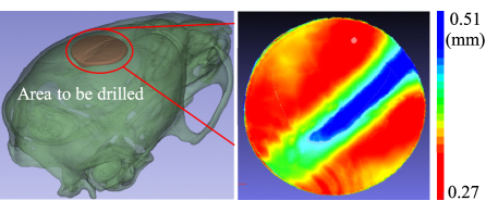
Biological specimens, unlike industrial components, exhibit significant variations in size and shape, and certain tissues possess a highly soft and deformable nature. This variability poses a challenge to robotic systems, which excel at performing repetitive or predefined motions, but struggle to automatically adapt to these variations. Consequently, the manipulation of biological specimens by robots often requires human operation, for instance, via a leader-follower robotic system. The complexity of this robotic manipulation increases when performed under a microscope, as in fields such as ophthalmology and neurosurgery where microsurgical tasks require high precision and accuracy [1, 2, 3, 4]. Similar technical challenges are encountered in the micromanipulation of cells, organoids, and small animals for medical research purposes. As a case in point, creating a skull window in mice, a procedure essential for medical science studies, presents significant technical challenges due to the need for microscopic manipulation [5]. The variability in skull thickness, ranging from 0.27 mm to 0.51 mm as shown in Figure 1 (based on [6]), and the lack of a method to visualize the thickness distribution, hinders the accuracy and success rates of manual micromanipulation, leading to the exploration of robotic approaches. These approaches aim to improve precision while compensating for physiological tremors, as demonstrated by systems such as SmartArm for vitreoretinal surgery and Symani111https://www.mmimicro.com/our-technology/symani-surgical-system/ and MUSA-3222https://microsure.nl/musa for plastic and reconstructive surgery [7, 8]. However, integrating preoperative information into these systems to further improve performance remains an area of development, particularly due to limitations in surface registration accuracy, which is essential for micromanipulation.
The current study focuses on addressing these challenges in the mouse cranial window creation task, where an accurate skull thickness measurement from preoperative models is critical to prevent brain damage during drilling. In addition, accurate registration with the actual skull incorporating preoperative knowledge is essential for safe autonomous robotic micromanipulation. Although several registration methods have been developed using 2D/3D features such as bregma/lambda landmarks or surface curvature [9, 10, 11], their efficacy has primarily been demonstrated on bare or exposed skulls. However, practical application faces obstacles like limited skull surface exposure and obstruction of key features by biological materials.
Existing registration methods for mice skulls Methods [9] [10] [11] Target Bare Skull Bare Skull Exposed Skull Automation Manual Autonomous Semi-Auto Perception Frame-based Depth Camera A low-force contact Approach Stereotaxy sensor Translational 0.53 ± 0.22 N/A 0.011 Errors (mm) Rotational N/A N/A Errors (0.17 ± 0.10, (degree) 0.10 ± 0.04, 0.14 ± 0.06)
To improve registration accuracy, the use of 3D imaging technologies, including RGB-D systems that provide both 2D features and surface curvature, is essential. Previous studies, such as that of [12], have demonstrated the potential of stereomicroscope-based 3D vision systems in microsurgery, achieving a Root Mean Square Error (RMSE) of approximately 0.15 mm. Despite their accuracy, structured light-based systems are limited by processing speed [13, 14, 10], highlighting the challenge of balancing precision with operational efficiency in robotic manipulation. In response to these challenges, this study investigates advanced imaging and registration techniques to improve robotic control in micromanipulations in medical applications, aiming to address the need for both accuracy and efficiency in real-time operations.
Autonomous registration is necessary to plan motion for individual patients or biomedical specimens, and in particular, accurate micromanipulation in microsurgery customized for each patient will greatly contribute to his or her quality of life after surgery. It should also be mentioned that since the COVID-19 pandemic, the importance of the safety of medical professionals and scientists has been reaffirmed, and the robotization of medical procedures and medical research experiments has received renewed attention. Accurate registration technology is an important element for human-robot interaction, improving the accuracy of micromanipulation in medicine, improving the postoperative quality of life of patients, and protecting medical professionals in telerobotic medicine applications.
In this paper, we aim to develop a MSCS for robotic micromanipulation and registration for mice skulls with cranial features on a microscopic scale. This paper’s contributions are threefold: (1) We have developed a MSCS employing a linear model that boasts an accuracy of 0.10 mm ± 0.02 mm and a processing speed of 30 frames per second (FPS), accelerated by a GPU-based disparity calculation algorithm; (2) We have demonstrated an accurate and precise registration scheme for the partially exposed cranial surface, utilizing CNN-based constrained and colorized registration methods; (3) We have integrated these methods and evaluated them through a mouse cadaver experiment.
2 Materials and Methods
2.1 Requirements and Specifications
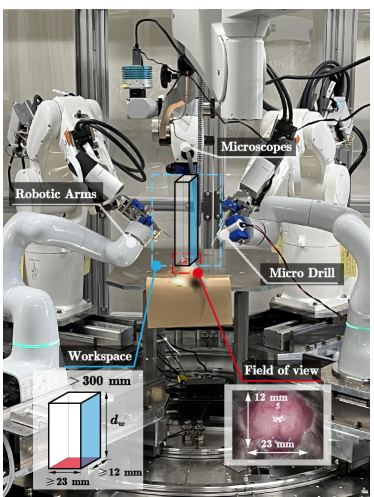
In the robotic platform for scientific experiments targeted in this work, the robotic end-effectors are spatially arranged for optimal functionality (see Figure 2 and Table 2.1). The field of view (FoV) is adjusted to accommodate a mouse skull specimen under these operation conditions. Regarding the required accuracy, from the template model proposed by the paper [6], it is found that the cranial skull’s thickness ranges from 0.27 mm to 0.70 mm. The suture regions exhibit greater thickness (0.32 mm to 0.70 mm), while other continuous areas are thinner (0.27 mm to 0.43 mm). To accurately observe the thinning of the cranial skull, the system’s depth resolution should be 0.14 mm or finer, which is approximately half of the minimum thickness of the cranial region. Furthermore, a frame rate exceeding 10 FPS is crucial to enable instant depth perception for human operators [15].
Requirements for the 3D Vision System Working Distance (mm) FoV (mm) Accu.(mm) FPS 300.00<d<600.00 W>12.00, H>23.00 <0.14 >10 \tabnoteW and H are Width and Height of the FoV; Accu.: Accuracy.
The FoV and the working distance requirements can be met by choosing a proper camera and macro lens setup. For a single microscope, follow the thin lens equation:
where is the focal length, is the magnification ratio, is the working distance of a single microscope.
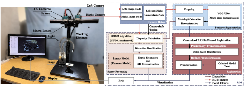
According to the requirements, we adopted the hardware configuration in Figure 3, where the camera STC-HD853HDMI (Omron Inc., Japan) and the macro lens VS-LDA75 (VS Technology Inc., Japan) are used to capture microscopic images with a FoV 73.8541.54 and around 500.00 mm (=75 mm, m=0.175). A video capture card (DeckLink Quad HDMI Recorder, Blackmagic Design Inc., USA) was used in the capturing. The primary reason for choosing VS-LAD75 was its optimal FoV and .
2.2 A Framework for Microscopic Registration with MSCS
We developed a MSCS and a registration scheme in Robot Operating System (ROS), as shown in Figure 3. This framework addresses the challenges associated with microscopic 3D reconstruction and registration using cranial features.
The specifications of hardware were discussed in Section 2.1 to meet the requirements. The MSCS captures stereo images from microscopes through the Camera Driver module. In the Stereo Processing module (Section 2.3), the images are used to calculate disparity maps by semi-global block matching (SGBM) algorithm and reconstruct RGB point clouds by the linear model (Section 2.3.1). The RGB-D images are utilized for feature segmentation and point cloud registration (Section 2.4). Finally, the reconstructed RGB point clouds and transformed model clouds are visualized in Rviz333http://wiki.ros.org/rviz.
2.3 Stereo Processing Workflow in MSCS
2.3.1 Depth Perception with An Orthographic Projection Model
The hardware system layout depicted in Figure 3 is conceptually simplified in Figure 4, where we posit a point within a 3D coordinate system . This point is simultaneously captured by both the left and right microscopes. The presentations of the point on the left and right microscopes are () and () regarding the microscopes’ perspective centers, respectively. The distances from the point to the centers are denoted as and . The projections of this point onto the image planes correspond to the pixels and , respectively. We assume that the orientations of both microscopes are aligned within the same plane ( plane) and converge at a fixed point, marked by a convergence angle of .
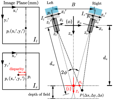
The Pinhole Model is extensively applied for calibration and depth perception in stereo camera systems, addressing perspective effects as discussed by [16]. The projection functions of the point on the image planes are defined based on the imaging geometry. For example, the projection in the left image plane can be expressed as:
where is the focal length of the macro lens, is deduced by coordinate rotation from Frame to left image plane frame .
in the denominator term equals point’s z-position in Frame adding an effective distance . Thus, the denominator term can be expressed regarding Frame :
In the context of stereo microscopy, where the FoV () and the depth of field () are significantly smaller than the working distance , we specifically address the calculation of under the configuration = 500.00 mm, = , B 135.00 mm, = 41.54 mm, 10.00 mm:
Consequently, the disparity-depth mapping function approximates an orthographic projection as per [16] for :
where the magnification ratio .
This projection presupposes alignment of the epipolar plane with the horizontal image coordinate axes of both microscopes’ views, ensuring distortion-free orthographic projection through the use of low-distortion macro lenses.
For practical calibration convenience using a checkerboard, we further streamline to a linear function (the linear model):
| (1) |
A point () in microscopic 3D space is projected to the left image of the microscope at a pixel () (pixel), where (pixel/mm) denotes the depth response to unit disparity in reality, (pixel) is the pixel’s disparity value, (mm) is the effective working distance of the stereo microscope setup (indicating the physical distance from Frame to Frame ), (pixel) are the camera’s principal point image coordinates. (pixel/mm) indicate the object’s pixel sizes in the x and y directions, respectively. The corresponding pixel (pixel) in the right image is essential for calculating the disparity value using a CUDA-accelerated SGBM algorithm [17].
2.3.2 Model Calibration and Distortion Rectification
In the context of the linear model, we calibrated factors such as using checkerboard images. For instance, we estimated the checkerboard’s pose (Square size: 0.50 mm x 0.50 mm) and identified the corners. The corners’ pixel distances and their true lengths (0.50 mm) relative to the pose were computed and averaged to determine the pixel size in millimeters, yielding values for . For , step-height experiments were conducted by incrementally elevating a z-axis stage and observing the corresponding disparity responses, from which the factor’s value was deduced by fitting a linear curve.
As per [18], a stereo microscope utilizing a common main objective (CMO) introduces specific CMO distortion. Although our research’s setup does not incorporate a CMO, the reconstruction of a planar object revealed a similar distortion mode as illustrated in Figure 5.
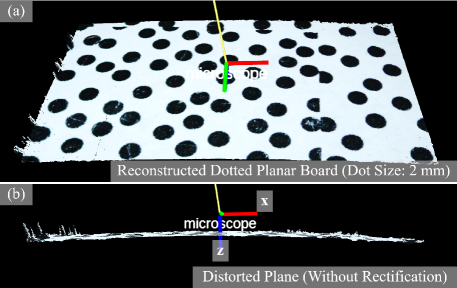
Given that the distortion-induced errors are uniformly distributed along the vertical axis, as identified by [18], we adopted a similar assumption for our analysis. To counteract these distortions, we differentiated between a horizontal planar object (illustrated by the dotted pattern in Figure 5(b)) and its z-axis transition from an ideal to a distorted planar surface. This method allowed us to effectively compensate for the constant residuals introduced by the distortion, ensuring a more accurate representation of the observed object.
2.4 The Registration Scheme with Pre-operative Planning
2.4.1 Pre-operative Planning and Cranial Features for Registration
For pre-operative planning utilizing CT-scan imagery, the selection of laboratory mice as subjects requires the utilization of micro-computed tomography (micro-CT) to precisely capture the craniofacial phenotype in three dimensions as shown in 6. The segmentation editor tool within the 3D Slicer444https://www.slicer.org/ software facilitates the delineation of the targeted circular area (marked in a color gradient), tailored to the precise location and thickness distribution.
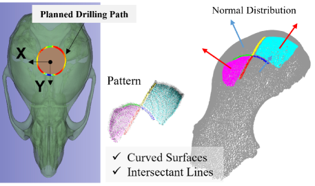
Adjacent to the drilling site, certain features facilitate the model’s alignment with the intraoperative RGB point cloud. From the colorless reconstructed model in Figure 6, only sutures and surfaces, discernible through the crevices, provide essential spatial information for successful registration. Curved surfaces convey critical orientation information, while intersectant lines (the sutures) pinpoint the exact spatial positioning necessary for pattern recognition.
2.4.2 Proposal of The Registration Scheme
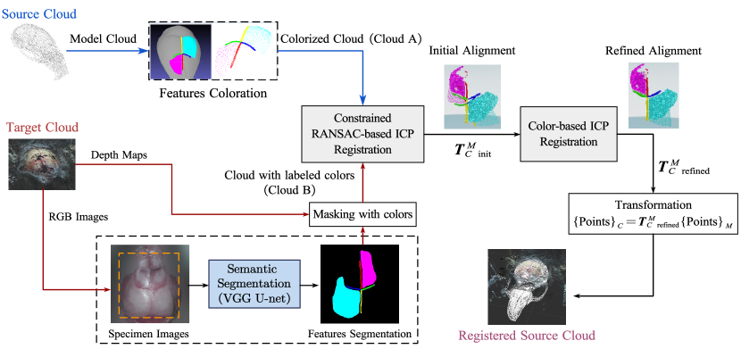
Our registration scheme matches patterned features of a colorless model with those in the corresponding RGB point cloud via manual coloration and multi-class feature segmentation, as outlined in Figure 7.
Features Coloration in Model
Initially, features in the model including intersectant lines and curved surfaces are colorized with labeled colors based on distinct RGB value discrimination (e.g., [1,0,1], [0,1,1]), as depicted in Figure 7. Employing varied colors corresponding to different orientations or feature locations aids the color-based ICP algorithm [19] in executing precise matching.
Features Segmentation from RGB-D images
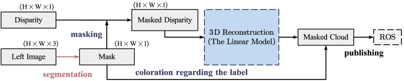
Underlying this scheme is the premise that cranial features are identifiable from RGB imagery of mice skulls. Thus, the features can be segmented with a multi-class semantic segmentation algorithm, where in this research, we used a VGG U-net model [20], as demonstrated in Figure 7. For mouse skull registration, a minimalist feature set is preserved, including four sutures and two facial areas between sutures, selected for their distinctive orientation information. The features are segmented into different classes through the neural network. The masks with class labels are used to segment the depth map as illustrated in the workflow in Figure 8. The resultant class-labeled masks facilitate depth map segmentation, as depicted in the workflow of Figure 8. Consequently, point clouds pertaining to features with designated RGB colors are color-matched rather than their original colors.
Point Cloud Registration
The process begins with aligning the preoperative model’s colorized point cloud (Cloud A) with the feature-segmented point cloud with labeled colors (Cloud B) to achieve registration within the microscopic 3D space. Given potential noise from reconstruction or segmentation misclassification in Cloud B, an initial alignment utilizing the RANSAC-based ICP method filters outliers and aligns the point clouds with the estimated surface normal of the surface features. The registration is constrained by its 2D orientation concerning the left image frame. The iteration of the color-based ICP method [19] is initialized with the output transformation . This method chiefly refines alignment by exploiting the colorized inline feature clouds. The finalized outcome is a polished transformation matrix employed to adjust the preoperative model.
3 Experimental results
3.1 Measuring Experiments
3.1.1 Evidence of the Linear Relationship in Depth Estimating
To ascertain whether the disparity-depth mapping function aligns more closely with a linear function than the conventional pinhole camera model, we conducted a comparative experiment. This involved a step-height measurement experiment within the field of view, focusing on the relative depth response to disparity changes. We incrementally elevated the stage along its z-axis by 0.50 mm increments, recording disparity values ten times at each position to obtain an average. Given a depth of field of approximately 10.00 mm, we documented 21 steps, as illustrated in Figure 9.
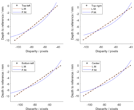
The experimental outcomes indicate a linear response (Figure 9), with L.M. achieving a fit characterized by (, RMSE, MAE)=(0.9996, 0.06, 0.05), in contrast to P.M., which yielded (, RMSE, MAE)=(0.9418, 0.73, 0.64). Here, represents the coefficient of determination, RMSE, and MAE the mean absolute error, demonstrating the linear model’s superior accuracy and consistency in depth estimation.
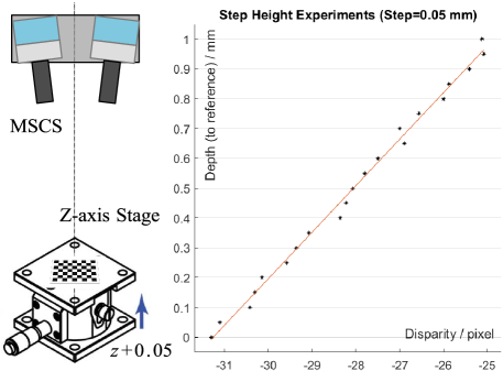
3.1.2 Experiments for Evaluating the Depth Resolution
A subsequent step-height experiment was designed to gauge the depth perception accuracy facilitated by the linear model, as depicted in Figure 10. This experiment involved adjusting the z-axis stage in 0.05 mm increments, with disparity measurements taken at each step, spanning a total of 21 samples from 0.00 mm to 1.00 mm. The results revealed a linear fit with =0.9941 and an RMSE of 0.02 mm at a resolution of (540960), signifying an enhancement over the 3D reconstruction error reported by [12] (approximately 0.15 mm at 1080P). Furthermore, the RMSE of 0.02 mm indicates that the average measurement error falls below the minimum detectable distance difference (0.10 mm), affirming the system’s capability to discern minute changes of 0.05 mm with uniform distribution. Consequently, we deduced that our system possesses a resolution of 0.10 mm in depth estimation.
3.2 Surface Registration Experiments
3.2.1 Experimental Objective and Setup
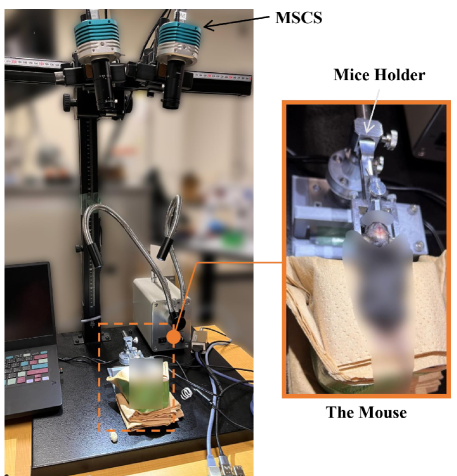
To evaluate the precision of the registration scheme, an euthanized 16-week-old mouse was used for the reconstruction and registration (refer to Figure 11). It is crucial to note that the mouse, provided by an adjacent research laboratory, was not specifically euthanized for this study but would have otherwise been disposed of.
We collected a training dataset (156 pictures, 512x512) from 10 different mice (including the dataset for testing the scheme, which has 10 of the 156 images) to train the network for the segmentation task. After augmentation, we fed the augmented dataset (9516 pictures, 512x512) to train the network, where the number of classes is 7, including 6 feature classes and 1 undefined class. The training was completed using a workstation with a Ryzen 9 5950X (AMD Inc., USA) and an RTX3080 (Nvidia Inc., USA).
The efficacy of the proposed registration scheme was evaluated through practical experiments involving a colorized model, as shown in Figure 6. As the training of the semantic segmentation network involved the images for validating the registration scheme, the results show the capability of the scheme under the condition of correct segmentation.
Leveraging the ROS-based system development enabled the capture of the cranial surface reconstruction sequence, utilizing the rosbag555http://wiki.ros.org/rosbag package for real-time replay within ROS.
Quantitative assessment of the registration’s precision entailed analyzing a specific sequence consisting of 105 frames, captured while the mouse head was static and fixed by a mouse head holder (SG-4N, Narishige, Japan). Although the reconstruction occurred in real-time, the mouse skull’s position was stationary, ensuring consistency in the evaluation of registration precision.
3.2.2 Evaluation Criteria and Results
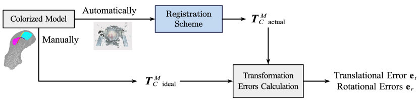
Due to the absence of a reference frame within the reconstructed mouse point clouds, we manually aligned the mouse bregma model with the cranial surface, utilizing the same feature chosen in the coloration. The translational and rotational errors were then assessed through a workflow illustrated in Figure 12.
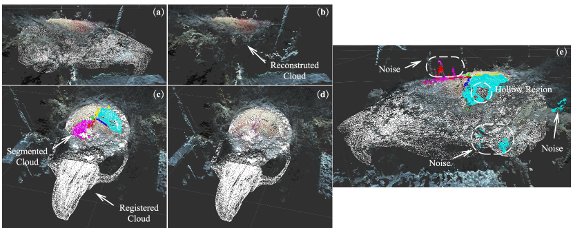
Following the autonomous registration process, the transformed bregma cloud was rendered within a 3D vision space, depicted as a white point cloud in Figure 13. Despite the presence of noise in Cloud B, as evidenced in Figure 13(e), the registration scheme demonstrated resilience to such disturbances, achieving accurate alignment with the cranial surface. This noise could originate from light reflections that failed to match any features during disparity calculations or from segmentation misclassifications.
Error calculations between the registered and manually aligned frames were conducted using the following equations:
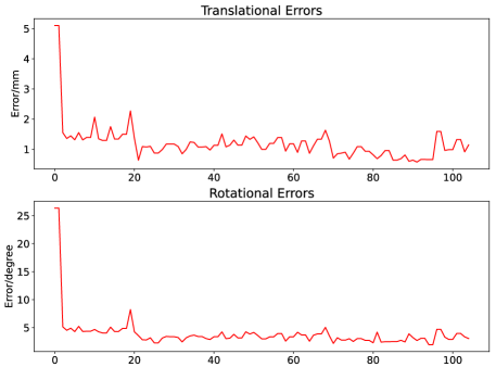
Here, represents the trace of , with and denoted in millimeters and degrees, respectively. Figure 14 delineates the translational and rotational errors across a sequence of 105 frames, highlighting an average processing duration of approximately 1.60 seconds for the entire scheme according to the nodes’ publication frequency in ROS. These findings underscore the system’s stability and robustness in registering static objects amidst variations in lighting and occlusions.
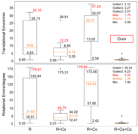
A comparative analysis with other methods, employing the identical sequence, is presented in Figure 15. This box plot contrasts four different combinations of registration methods, delineating variations with and without constraints (Cs) or colorization (Co). While the minimum errors across the methods were comparably similar, notable differences were observed in their deviations. The application of constraining techniques effectively limited deviations, yet lacked precision with random distributions. Color-based registration yielded the lowest error rates among the tested methods, although it demonstrated susceptibility to noise within the point cloud. A synergistic integration of both techniques culminated in the most favorable outcomes—minimizing deviation and registration errors. Excluding outliers shown in Figure 15, the scheme attained the lowest average translational error (mean 1.13 ± 0.31 mm, excluding outliers 5.10, 2.27, and 2.07 mm) and rotational error (mean 3.38° ± 0.89°, excluding outliers 26.34° and 8.23°). As the outliers mainly occurred at the beginning of the registration, the errors show the registration accuracy when the transformation became stable.
4 Discussion
This study introduced the integration of a Microscopic Stereo Camera System (MSCS) augmented by a simplified stereo microscopy model, termed the linear model, for depth perception. Demonstrating high precision in the step height experiment, the system attained 0.10 mm accuracy with an RMSE of 0.02 mm, as detailed in Figure 10. Meeting the real-time performance criteria outlined in Section 2.1, the system’s processing capability has been optimized to achieve up to 30 FPS in ROS, making it suitable for both manual and automated interventions. This optimization enables it to outperform comparative methods ([11, 13, 14, 12, 10]), ensuring efficient and effective operation as listed in Table 4. Nonetheless, the system’s performance on biological specimens is hindered by reflective surfaces, which compromise disparity calculations due to lost correlations. The proposed linear model can provide accurate relative depth reconstruction. Although we defined the effective working distance for its use in stereo microscopy, achieving precise calibration for absolute depth reconstruction remains a challenge. For practical implementation, the effective working distance can be set to 0 without compromising registration accuracy. Further endeavors will aim to improve the system’s robustness to the reflection and accurate calibrating of the working distance.
Comparison of depth perception methods in related work Works [11] [13] [14] [12] [10] Ours Methods Force SL SL Dense SL SGBM disparity (mm) N/A N/A 8996 N/A 250 500 FoV (mm) N/A 30×35 3.9°-0.6°1 12×23 135×222 22×35 Accuracy (m) 11 98.5 ± 4.5 ± 4.0 (X, Y) 150 10 ± 2 100 ± 20 at ± 7.5 (Z) at 1080P 540×960 FPS N/A 0.01 N/A 5 0.9 30 \tabnote1with a range of view 6.0-1.0 mm; SL: Structured Light.
Further, a novel registration scheme was developed to leverage this system for microscopic registration on patterned surfaces. The challenges in the registration include 1) little 3D features on the exposed cranial surface, 2) partial visibility or occlusion by the biological tissues or the instrument, and 3) inconsistent feature spaces between the preoperative model with channels (x,y,z) and the intraoperative point cloud with channels (x,y,z,R,G,B). According to [21], existing state-of-the-art registration strategies can be categorized into two types: End-to-End and hybrid methods. The End-to-End method directly learns features from the point clouds through the neural network and regresses the transformation of the source clouds. However, applying this kind of method is difficult mainly because of the inconsistent feature spaces between the model and the intraoperative cloud. Therefore, the research focuses on developing a hybrid method for registration. Current hybrid methods detect key points from the point clouds for matching. Regarding the biological specimens, key point detection is not robust enough as the operation has unpredictable occlusions. Besides, the anatomical landmarks may be hard to recognize because the appearance of each individual is different. Inspired by contextualization in [22], which extracts semantic information from 2D or 3D data to handle the inconsistencies between the feature spaces in medical image registration, we investigated related research in this field to register two data with inconsistent feature spaces. However, another strategy using contour features for registration like [23] is not applicable to the task, as there are no fixed contour features on the partially exposed cranial surface.
Therefore, regarding the limitations of current registration strategies with hybrid methodology, we developed a registration scheme with a novel feature descriptor for the registration between the preoperative model and the intraoperative RGB point cloud of a biological specimen on a microscopic scale in Section 2.4. Rather than landmarks or contours, the scheme selects the lines and surface features for registration, where, in a mouse case, they are the sutures and surfaces on the cranial surface. The feature includes enough position and orientation information for accurate registration. Another novel method is converting the contexts to labeled colors to utilize the context for registration. Instead of keeping the original RGB information, we segmented the features semantically from RGB point clouds as multiple classes and labeled colors regarding the classes. In the preoperative model, we painted the points belonging to the same context with the same context color. Registration is performed between the two clouds using the same context colors.
We compared the feature descriptor with others in Table 1. The proposed method can handle more complicated features and achieve more accurate registration than others, showing the proposed method’s advancement.
End-to-End Hybrid Strategy (Contextualization) Feature descriptor Neural Network Key-points-based Contour-based Surface + Intersectant lines Feature space Cloud features Points Lines Points/Lines/Surfaces Channel XYZ+(RGB) XYZ XYZ XYZ+RGB (labeled) Requirements Inconsistent channels - + + + Partial visibility (Occlusion) + - + + Surface Curvature (Orientation) + - - + Individual Differences1 - - + + Dataset Inaccurate Inaccurate Inaccurate Accurate \tabnote1Appearances change regarding different individuals.
The MSCS and the registration scheme presented have broad applications, extending to microsurgeries and micro-electromechanical system (MEMS) manufacturing, as discussed in the introduction. The registration scheme is particularly applicable in scenarios like craniotomy or plastic and reconstructive surgery, where surfaces with preoperative models possess visible patterned features, despite being limited to microscopic views. In addition to reconstruction accuracy for such applications, it is imperative to recognize the importance of ensuring safety in robot-human interactions. Therefore, further efforts will also focus on applying the developed technologies to other applications to demonstrate how our technologies can contribute to robotic micromanipulation in medicine, for example, to ensure patient safety in microsurgery or to ensure the safety of medical researchers while successfully performing robotic micromanipulation tasks in a remote space.
5 Conclusions
This study develops and evaluates a Microscopic Stereo Camera System (MSCS) and a registration scheme, addressing the challenges in microscopic manipulation for scientific and surgical applications. The MSCS demonstrates remarkable accuracy (0.10 mm ± 0.02 mm) and real-time processing capability (30 FPS), laying a solid foundation for precise control in delicate procedures. Additionally, the registration scheme, employing CNN-based methods tailored for patterned surfaces with intersectant lines and normal features, exhibits rapid yet stable performance even in complex scenarios. Notably, in the application of mice skull registration, the translational error is measured at 1.13 mm ± 0.31 mm, with a rotational error of 3.38° ± 0.89° over 105 continuous frames, achieved within a 1.60 seconds per registration. In the future, the technologies developed will be integrated into other applications to ensure both the performance and safety of micromanipulation in surgery and medical research.
Acknowledgement(s)
The authors would like to thank our research collaborators and scientists for their fruitful comments, especially Professor Murilo Marques Marinho, for his kind help in improving this work.
Disclosure statement
All authors declare no financial or personal relationships with other people or organizations.
Ethical approval
The animal had been euthanized in another study and was reused in our study, thus no ethical approval was required.
Funding
This study was supported in part by JST Moonshot R&D JPMJMS2033-09 and in part by the University of Tokyo Fellowship.
References
- [1] Sha X, Sun H, Zhao Y, et al. A review on microscopic visual servoing for micromanipulation systems: Applications in micromanufacturing, biological injection, and nanosensor assembly. Micromachines. 2019;10(12):843. Publisher: MDPI.
- [2] van Mulken TJ, Schols RM, Qiu SS, et al. Robotic (super) microsurgery: feasibility of a new master-slave platform in an in vivo animal model and future directions. Journal of surgical oncology. 2018;118(5):826–831. Publisher: Wiley Online Library.
- [3] Clarke NS, Price J, Boyd T, et al. Robotic-assisted microvascular surgery: skill acquisition in a rat model. Journal of Robotic Surgery. 2018 Jun;12(2):331–336.
- [4] Takebe T, Wells JM. Organoids by design. Science. 2019 Jun;364(6444):956–959. Publisher: American Association for the Advancement of Science; Available from: https://www.science.org/doi/full/10.1126/science.aaw7567.
- [5] Marques Marinho M, Quiroz-Omaña JJ, Harada K. A multi-arm robotic platform for scientific exploration. IEEE Robotics and Automation Magazine (RAM). 2024;Available from: https://arxiv.org/abs/2210.11877.
- [6] Maga AM, Tustison NJ, Avants BB. A population level atlas of Mus musculus craniofacial skeleton and automated image‐based shape analysis. Journal of Anatomy. 2017 Sep;231(3):433. Publisher: Wiley-Blackwell; Available from: https://www.ncbi.nlm.nih.gov/pmc/articles/PMC5554826/.
- [7] Koyama Y, Marinho MM, Mitsuishi M, et al. Autonomous Coordinated Control of the Light Guide for Positioning in Vitreoretinal Surgery. arXiv:210711985 [cs]. 2021 Jul;ArXiv: 2107.11985; Available from: http://arxiv.org/abs/2107.11985.
- [8] Aitzetmüller MM, Klietz ML, Dermietzel AF, et al. Robotic-assisted microsurgery and its future in plastic surgery. Journal of Clinical Medicine. 2022;11(12):3378. Publisher: MDPI.
- [9] Spyrantis A, Woebbecke T, Rueß D, et al. Accuracy of Robotic and Frame-Based Stereotactic Neurosurgery in a Phantom Model. Frontiers in Neurorobotics. 2022;16. Available from: https://www.frontiersin.org/articles/10.3389/fnbot.2022.762317.
- [10] Wu Y, Chen H, Han B, et al. A Novel Method for Preoperative 6D Pose Estimation of Rat Skull Based on 3D Vision Techniques. In: 2021 27th International Conference on Mechatronics and Machine Vision in Practice (M2VIP); Nov.; 2021. p. 223–228.
- [11] Ghanbari L, Rynes ML, Hu J, et al. Craniobot: A computer numerical controlled robot for cranial microsurgeries. Scientific reports. 2019;9(1):1023. Publisher: Nature Publishing Group UK London.
- [12] Probst T, Maninis KK, Chhatkuli A, et al. Automatic tool landmark detection for stereo vision in robot-assisted retinal surgery. IEEE Robotics and Automation Letters. 2017;3(1):612–619. Publisher: IEEE.
- [13] Ly PT, Lucas A, Pun SH, et al. Robotic stereotaxic system based on 3D skull reconstruction to improve surgical accuracy and speed. Journal of neuroscience methods. 2021;347:108955. Publisher: Elsevier.
- [14] Wang Y, Chen J, Peng Y. Surface Reconstruction of Microscale Objects Based on Grid-Patterned Structured-Light Measurements. Microscopy and Microanalysis. 2022 Feb;28(1):152–172. Available from: https://www.cambridge.org/core/product/identifier/S1431927621013829/type/journal_article.
- [15] Miller RB. Response time in man-computer conversational transactions. In: Proceedings of the December 9-11, 1968, fall joint computer conference, part I; New York, NY, USA. Association for Computing Machinery; 1968. p. 267–277; AFIPS ’68 (Fall, part I). Available from: https://doi.org/10.1145/1476589.1476628.
- [16] Kim N, Bovik A, Aggarwal S. Shape description of biological objects via stereo light microscopy. IEEE Transactions on Systems, Man, and Cybernetics. 1990 Apr;20(2):475–489. Available from: http://ieeexplore.ieee.org/document/52557/.
- [17] libSGM ; 2023. Original-date: 2016-02-12T07:43:44Z; Available from: https://github.com/fixstars/libSGM.
- [18] Danuser G. Photogrammetric calibration of a stereo light microscope. Journal of Microscopy. 1999;193(1):62–83. _eprint: https://onlinelibrary.wiley.com/doi/pdf/10.1046/j.1365-2818.1999.00425.x; Available from: https://onlinelibrary.wiley.com/doi/abs/10.1046/j.1365-2818.1999.00425.x.
- [19] Park J, Zhou QY, Koltun V. Colored Point Cloud Registration Revisited. In: 2017 IEEE International Conference on Computer Vision (ICCV); Oct.; 2017. p. 143–152. ISSN: 2380-7504; Available from: https://ieeexplore.ieee.org/document/8237287.
- [20] Gupta D. Image Segmentation Keras : Implementation of Segnet, FCN, UNet, PSPNet and other models in Keras ; 2023. ArXiv:2307.13215 [cs]; Available from: http://arxiv.org/abs/2307.13215.
- [21] Zhao Y, Fan L. Review on Deep Learning Algorithms and Benchmark Datasets for Pairwise Global Point Cloud Registration. Remote Sensing. 2023 Apr;15(8):2060. Available from: https://www.mdpi.com/2072-4292/15/8/2060.
- [22] Unberath M, Gao C, Hu Y, et al. The Impact of Machine Learning on 2D/3D Registration for Image-Guided Interventions: A Systematic Review and Perspective. Frontiers in Robotics and AI. 2021 Aug;8. Publisher: Frontiers; Available from: https://www.frontiersin.org/articles/10.3389/frobt.2021.716007.
- [23] Koo B, Robu MR, Allam M, et al. Automatic, global registration in laparoscopic liver surgery. International Journal of Computer Assisted Radiology and Surgery. 2022 Jan;17(1):167–176. Available from: https://doi.org/10.1007/s11548-021-02518-7.