DRACO: Differentiable Reconstruction for Arbitrary CBCT Orbits
Abstract
This paper introduces a novel method for reconstructing cone beam computed tomography (CBCT) images for arbitrary orbits using a differentiable shift-variant filtered backprojection (FBP) neural network. Traditional CBCT reconstruction methods for arbitrary orbits, like iterative reconstruction algorithms, are computationally expensive and memory-intensive. The proposed method addresses these challenges by employing a shift-variant FBP algorithm optimized for arbitrary trajectories through a deep learning approach that adapts to a specific orbit geometry. This approach overcomes the limitations of existing techniques by integrating known operators into the learning model, minimizing the number of parameters, and improving the interpretability of the model. The proposed method is a significant advancement in interventional medical imaging, particularly for robotic C-arm CT systems, enabling faster and more accurate CBCT reconstructions with customized orbits. Especially this method can also be used for the analytical reconstruction of non-continuous orbits like circular plus arc. The experimental results demonstrate that the proposed method significantly accelerates the reconstruction process compared to conventional iterative algorithms. It achieves comparable or superior image quality while reducing noise, as evidenced by metrics such as the mean squared error (MSE), the peak signal-to-noise ratio (PSNR), and the structural similarity index measure (SSIM). The validation experiments show that the method can handle data from different trajectories, demonstrating its flexibility and robustness across different scan geometries. Our method demonstrates a significant improvement, particularly for the sinusoidal trajectory, achieving a 38.6% reduction in MSE, a 7.7% increase in PSNR, and a 5.0% improvement in SSIM. Furthermore, the computation time for reconstruction was reduced by more than 97%. Code is available at https://github.com/ChengzeYe/Defrise-and-Clack-reconstruction.
-
October 2024
Keywords: CT Reconstruction, Deep Learning, Known Operator, Arbitrary Trajectory
1 Introduction
Cone beam computed tomography (CBCT) is a widely used imaging technique in interventional medicine. It employs a cone-shaped X-ray beam, which captures a substantial amount of data in a single rotation, thereby facilitating the generation of three-dimensional (3D) volume while concurrently reducing radiation exposure.
Traditional CBCT scans usually involve a rotating structure with a fixed circular orbit for the X-ray source and detector. In contrast, recent robotic C-arm CT systems provide greater flexibility, which expand the scanning geometries beyond the conventional circular source-detector trajectory.
Flexible CT orbits offer numerous advantages, particularly in the field of interventional medicine. These advantages include enhanced image quality, an extended field of view (FOV), a reduced radiation dose [1, 2], and a reduction in metal artifacts [3].
However, if the orbit of the X-ray source follows a non-circular path, this presents a challenge to the reconstruction process. In such cases, the commonly used analytical algorithms, such as Filtered Back Projection (FBP), are no longer applicable, as they are based on the assumption of a circular trajectory.
Prior research has made significant strides in addressing the challenge of reconstructing images from non-circular orbital configurations. For example, Zeng [4] introduced an Algebraic Iterative Reconstruction (AIR) algorithm that is adept at reconstructing CBCT projections from arbitrary orbits.
A more sophisticated iterative algorithm, Model-Based Iterative Reconstruction (MBIR) [5], was subsequently developed. The application of MBIR has been demonstrated to markedly enhance image quality while simultaneously reducing noise and artifacts, thereby outperforming the AIR algorithm [6]. In addition to MBIR, some iterative reconstruction algorithms based on conjugate gradient descent are noted for their rapid convergence and low error, and can be adapted to arbitrary CBCT orbits [7, 8].
Due to the necessity of multiple iterations to progressively approximate the final reconstruction result, iterative algorithms have a high computational complexity and long processing times.
A notable contribution was made by Grangeat [9], who proposed an exact reconstruction method for arbitrary orbits based on the relationship between the cone beam data and a function associated with the 3D Radon transform of the images. But this requires building an intermediate function matrix, which makes reconstruction relatively slow and memory intensive.
To address these limitations, Defrise and Clack [10] introduced a filtered backprojection-type algorithm based on Grangeat’s method. This approach customizes the algorithm for different orbits by designing specific redundancy weights, thereby achieving analytic reconstruction for any CBCT orbit. However, the analytic calculation of these weights for complex orbits in practical applications is a challenging task.
In recent years, deep learning has become a widely used technique for fitting complex functions. But in the case of complex problems like the inverse problem in CT reconstruction, deep learning can lead to overparameterized models. Hence, Maier et al. [11] proposed a method to address this issue, namely the integration of known operators as prior knowledge into machine learning models. This approach reduces the complexity of the model by minimizing the number of parameters, thereby enhancing the precision, interpretability and reliability of the model [12].
Building on the integration of known operators, our previous work provided an overview [13] of the extension of the shift-variant FBP algorithm, leading to the development of a differentiable shift-variant FBP neural network for specific CBCT reconstruction. In this approach, the redundancy weights from Defrise and Clack’s algorithm are optimized through a training process, where parameters are fitted based on a given circular orbit. This demonstrates the potential for rapid reconstruction of CBCT scans for any specific orbits.
This work builds upon our previous conference paper [13] propose a differentiable shift-variant FBP neural network designed for arbitrary CBCT orbits reconstruction using known operator learning. In comparison to our previous work, we concentrate on optimising the operators within the reconstruction pipeline and on the design of a suitable synthetic dataset, which considerably enhances the model’s accuracy and fidelity. Furthermore, we conduct more extensive experiments to evaluate the model’s capability in handling data from more complex non-circular orbits, and we validate its performance using medical data, thus ensuring greater robustness and practical applicability.
The remainder of this paper is organized as follows: Section 2 outlines the theoretical background of our method. Sections 3 and 4 present experiments and results using circular, sinusoidal, circle plus arc orbits, and random nearest neighbor orbit. Finally, Section 5 presents a discussion of the advantages and limitations of our model, while Section 6 concludes the paper and outlines potential future directions for enhancing its performance.
2 Methods
2.1 Grangeat’s Inversion
Grangeat [9] proposed a reconstruction method that establishes a link between cone-beam projections and the first derivative of the Radon transform by defining an intermediate function. This method facilitates the rebinning process from the Cartesian coordinate system of cone-beam geometry to the spherical coordinate system of the Radon domain, utilising a plane as an information vector. Building upon this, Zeng [4] outlines a process whereby a multitude of lines are sampled on each cone-beam projection. The line integral along these lines can be viewed as a plane integral weighted by . The aforementioned plane is characterised by two parameters: the distance to the origin, which lies within the range , and a vector, designated as , which is orthogonal to the plane.
Based on this observation, Grangeat’s intermediate function (1) can be expressed as follows:
| (1) |
where denotes the parameter for the source position , (where is the set of all unit vectors in ) indicates the direction of the line integral, the function represents the cone-beam projection, and signifies the derivative of the Dirac delta distribution.
The intermediate function can be incorporated into the inverse Radon transform formula, thereby deriving the reconstruction formula (2) for Grangeat’s method:
| (2) |
This formular can already be adapted to arbitrary CBCT orbits. However, its main drawback is that it is not a FBP algorithm, as it necessitates data rebinning. The rebinning process entails interpolation, which may result in significant errors.
2.2 Shift-variant filtered backprojection algorithm
Defrise and Clack [10] introduced a shift-variant FBP algorithm based on Grangeat’s method, designed for the reconstruction of projection data from general non-circular orbits. In contrast to Grangeat’s algorithm, this approach circumvents the necessity to store intermediate functions on a discrete grid, thereby enabling the acquisition and reconstruction of projections to occur concurrently. This markedly accelerates the reconstruction process. The reconstruction formula is as follows:
| (3) |
where the term is defined as the number of intersections between orbit and the plane orthogonal to through orbit point .
Equation (3) can be broken down into three distinct components. Firstly, for each cone-beam projection , Grangeat’s intermediate function is computed using (1). Second, shift-variant filtering is applied to the resulting intermediate function:
| (4) |
Finally, as with the conventional Feldkamp-Davis-Kress (FDK) algorithm, the filtered cone-beam projections are backprojected into the 3D volume:
| (5) |
2.3 Differentiable shift-variant FBP neural network
In our preceding work [13], we gave an overview of how Defrise and Clack’s algorithm into a trainable neural network. In the following, we summarize the most important steps to derive the differentiable formulation of the Defrise and Clack’s algorithm.
For each projection, it is first necessary to compute Grangeat’s intermediate function , which serves to transform the cone-beam projection from the detector coordinate system into the Radon domain. As a consequence, it is first necessary to define a detector coordinate system for each detector position, as illustrated in Figure 1.
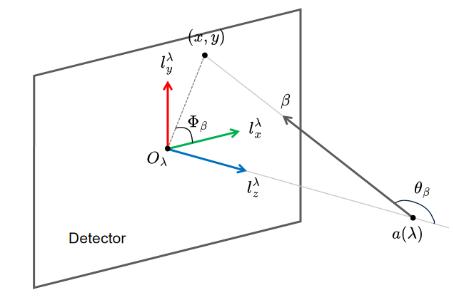
Furthermore, it is necessary to establish a sinogram coordinate system. The function is dependent upon the unit vector , which defines a plane that is orthogonal to and passes through the source. This plane intersects the detector plane along a line, which can be parameterised by the perpendicular distance from the detector centre to the line and the angle between this perpendicular and the x-axis.
In accordance with the definitions provided, Equation (6) can be derived from (1) as presented by Defrise and Clack [10]:
| (6) |
In this equation, and represent coordinate transformations defined as and , while denotes the distance between the source and the detector. In addition, the variable represents the radius of the region defined by the cone-beam projection of the field of view.
According to (6), The calculation of Grangeat’s intermediate function can be divided into three stages, each of which corresponds to a layer in the neural network architecture. The initial stage of the process entails the application of a cosine weighting function , defined as , to the input projection data . In the second step, a 2D Radon transform is performed using parallel beam geometry to project the weighted cone-beam data. This step yields the representation of the weighted cone-beam projection in the Radon domain. Finally, differentiation with respect to of the resulting sinogram is computed. Following differentiation, an additional weighting function , defined as , is applied within the sinogram domain.
Collectively, these operations constitute the computational pipeline for generating Grangeat’s intermediate function in the neural network framework, ultimately leading to as follows:
| (7) |
This equation differs from (6) mainly in the order of integration and differentiation being switched. The purpose of this switch is to reduce the noise caused by the differentiation process. Using (7), we construct the neural network shown in Figure 2

In accordance with the description provided in Section 2.3, the computed intermediate function must be processed with a shift-variant filter in order to obtain the filtered cone-beam projection. Specifically, it is necessary to explicitly rewrite (4) for the case where the cone-beam data are acquired on a planar detector. This process leads to the derivation of (8), as originally presented by Defrise and Clack [10]:
| (8) |
In the original equation (4), the function is discontinuous, and this discontinuity can lead to the formation of artifacts in a discrete implementation. Defrise and Clack addressed this issue by substituting the crofton symbol with a differentiable continuous function:
| (9) |
where be a positive integer, is a smooth function that is equal to one throughout the entire interval , with the exception of the region near the interval boundaries.
It is of great importance to obtain a continuous, differentiable function with properties similar to the crofton symbol in order to achieve optimal reconstruction quality. However, the practical application of Eq. (9) is subject to numerous constraints. For instance, how to appropriately choose the parameter based on the complexity of the orbit geometry. if the constant is not learned in a data-driven manner, it may not represent the optimal choice for different trajectories and applications.
In this work, we refer to the product of orbit-related term and the crofton symbol as the redundancy weight. This weight can be treated as trainable parameters in the reconstruction pipeline, and automatically estimated based on the given orbital geometry through the training of the neural network.
Similarly, Equation (8) can be decomposed into four steps, with each step corresponding to a layer in the neural network. First, the redundancy weight, defined as follows:
| (10) |
is applied to the intermediate function. This corresponds to the redundancy weight layer in the network, which is the only layer containing trainable parameters. Subsequently, the weighted intermediate function is differentiated with respect to in the sinogram domain using the operator . Then, the sinogram after differentiation is backprojected into the detector coordinate system using the same parallel beam geometry via the backprojection operator . Ultimately, the weight is applied in the detector domain for geometric correction. By combining the above steps, the following formula is obtained:
| (11) |
Based on eq. (11), the filtering step of the neural network can be constructed as shown in Figure 3.

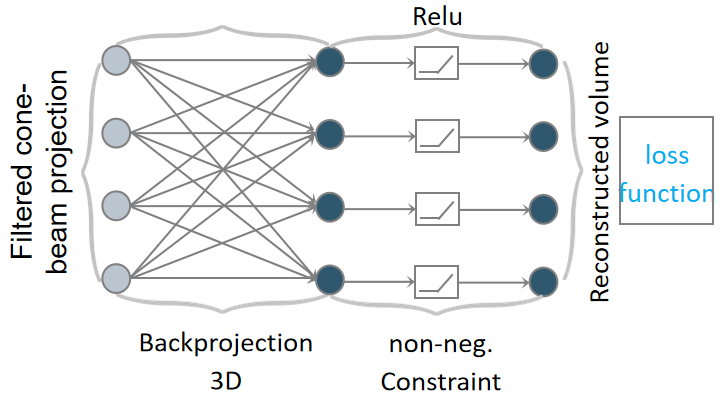
The aforementioned steps involve shift-variant filtering of the cone-beam projection data, which is subsequently backprojected into a 3D volume, designated as , which serves as the ultimate layer of the network. Following the 3D back-projection, a ReLU activation function is applied to ensure non-negativity of the output, as illustrated in Figure 4.
3 Experiments
The differentiable shift-variant FBP neural network exhibits trajectory geometric specificity, meaning that when the input projection data corresponds to different geometric trajectories, the model must be trained for each trajectory geometry. In order to validate the performance of our model, we utilise three distinct types of trajectory geometries: circular, sinusoidal, circle plus arc, and random nearest neighbor orbit. We generate simulated datasets based on each of these geometries, which is then employed to train the neural network and optimise its parameters. Meanwhile, a test set following the same geometry generated from real data is used to evaluate the network’s performance.
3.1 Implementation Details

To ensure smoothness in the learned redundancy weights, a Gaussian filter layer with a sigma value of 20 and a kernel size of 121 was added after the redundancy weight layer. This effectively reduces the noise interference in reconstruction process and improves the reconstruction quality.
We used PyTorch 2.1.1 to construct the neural network’s architecture. The 2D Radon transform and the 3D cone-beam backprojection were implemented using operators from the framework PyroNN [14].
The loss function for training is formulated as:
| (13) |
where represents the mean squared error (MSE) loss, denotes structural similarity index (SSIM) loss, and is a weighting factor. Following the normalization of the reconstructed result and the reference, the loss was calculated and the parameters were updated using the AdamW optimiser. The application of the One-cycle learning rate policy [15], which adjusted the learning rate cyclically between and over epochs, resulted in a notable enhancement in the training performance. Furthermore, a random initialisation was conducted for the redundancy weight layer , utilising values that were uniformly distributed between -1 and 0. Finally, the training process was conducted on an Nvidia A40 GPU.
3.2 Geometry Configuration
In our experiments, we employ the precise geometry parameters of a clinical C-arm system, the Artis zeego (Siemens AG, Forchheim, Germany). The detector matrix is operated in a 4 × 4 binning mode with 620 × 480 pixels at an isotropic pixel size of 0.616 mm. The source-to-detector distance is 1200 mm, and the source-to-center of rotation distance is 750 mm. A total of 400 projections are utilized for reconstruction. The reconstruction matrix is of dimensions 128 × 512 × 512, with a voxel size of 0.25 × 0.25 × 0.25 mm. In distinct experiments, the positions of the sources follow circular, circle plus arc, sinusoidal trajectories, and random nearest neighbor orbit, respectively.
The aforementioned parameters are presented in Table 1 for convenient reference.
| Volume shape | Volume spacing | Number of projections |
|---|---|---|
| 128512512 | 0.25mm0.25mm0.25mm | 400 |
| Source isocenter distance | Source detector distance | Detector spacing |
| 750mm | 1200mm | 0.616mm0.616mm |
| Detector shape | Source geometry | |
| 620480 | Cone beam |
Table 2 presents the geometric parameters utilized in the 2D Radon transform and backprojection processes within the differentiable shift-variant FBP reconstruction pipeline. The parameters are selected based on the detector shape and spacing to ensure complete sampling of the projection data.
| Volume shape | Volume spacing | Number of projections |
|---|---|---|
| 620480 | 0.616mm0.616mm | 360 |
| Angular range | Source isocenter distance | Source detector distance |
| 241mm | 483mm | |
| Detector shape | Detector spacing | |
| 785 | 0.616mm |
3.3 Training Data
A total of simulated data samples are generated in order to create a suitable training and validation dataset. of the samples are utilized for training, while the remaining samples are employed for validation.
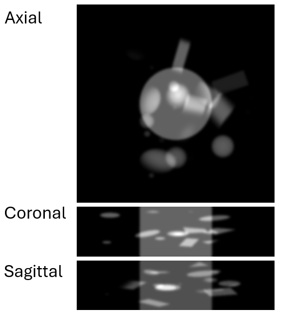
As the ground truth in each sample, a random number of geometric objects are generated within a voxel volume. These objects vary in type, position, and rotation direction. Furthermore, we incorporate cylinders with randomly generated diameters along the first dimension to make the simulated dataset more similar to the human thoracic and abdominal structures. Finally, in order to mitigate the impact of sharp edges on neural network training, Gaussian filtering is applied. Figure 6 illustrates central slices of the ground truth obtained from three directions.
We follow the orbit geometry presented in Table 1 and use the cone beam forward projection of the software PyroNN [14] to generate the sinogram, which serves as input for the neural network.
3.4 Real Data
In order to assess the efficacy of the differentiable shift-variant FBP neural network, we utilized the Pancreatic-CT-CBCT-SEG dataset [16], which was provided by the Memorial Sloan Kettering Cancer Center and included CT imaging data from 40 patients with pancreatic cancer.
A total of five samples were selected in the experiment, using the same approach employed in Section 3.3 to generate the corresponding sinogram for testing purposes.
4 Results
4.1 Circular Orbit
First, we employ the circular orbit data, as its straightforward structure permits the straightforward derivation of the analytical solution for comparison.
The analytical solution of the redundancy weight for circular orbit is defined as follows:
| (14) |
which reveals that each source position corresponds to an identical redundancy weight. Leveraging this insight as prior knowledge can significantly reduce the number of parameters required by the differentiable shift-variant FBP neural network in such scenarios, thereby accelerating convergence rates. Specifically, the network converges within epochs when the learning rate is set to .
In Figure 7, the visualisation of learned redundancy weight layer parameters is presented, compared with the analytical solution, and it is demonstrated that they have similar structures. However, the redundancy weights display distinct characteristics when compared to the analytical solution in regions where the value of is either extremely large or small. This is due to the fact that the Grangeat’s intermediate function is equal to zero in these regions, which results in a zero contribution to the gradient update of the weights.
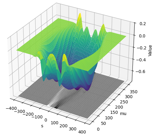
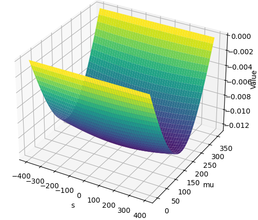
Table 3 employs MSE, Peak Signal-to-Noise ratio(PSNR), and SSIM as quantitative evaluation metrics to analyze the efficacy of the learned weights for reconstruction. Given that the reconstructed volume exhibits discrepancies in pixel intensity when compared to the ground truth, we apply histogram matching to the reconstructed result prior to calculating the quantitative metrics. It can be observed that the learned redundancy weights yield results that are in close alignment with the analytic redundancy weights, with only minor discrepancies. These minor discrepancies may be attributed to the selection of the loss function or the optimiser’s hyperparameters.
| Weighting type | MSE | PSNR (dB) | SSIM |
|---|---|---|---|
| Learned | 0.0945± 0.0136 | 36.79±1.38 | 0.9531±0.0057 |
| Analytical | 0.0983±0.0126 | 36.43±1.44 | 0.9684±0.0036 |
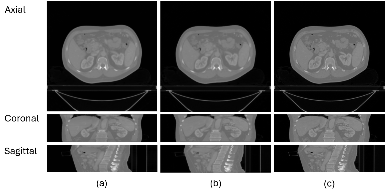
In Figure 8, a comparison of the central slice of volumes reconstructed with different redundancy weights is presented. The results show that the neural network, after training, can achieve reconstruction results similar to those obtained through the analytical method.
4.2 Sinusoidal Orbit
The sinusoidal trajectory is a commonly used trajectory in the field of medical imaging. It has been demonstrated that this trajectory can effectively reduce metal artifacts [17]. In the spherical coordinate system, it can be expressed as follows:
| (15) |
where represents the traditional gantry rotation angle, which ranges from to . Additionally, denotes the gantry tilt angle. The maximum tilt angle is represented by . defines the frequency of the sinusoid. In this experiment, a sinusoidal trajectory with a maximum tilt angle of and a frequency of is employed, as illustrated in Figure 9.
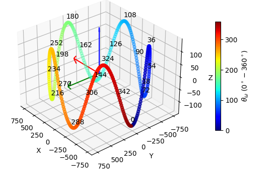
Figure 10 depicts the parameters within the redundancy weight layer following the convergence of the neural network after epochs with an initial learning rate of . It can be observed that as the trajectory undergoes periodic alterations, the redundancy weight also exhibits corresponding periodic behaviors.
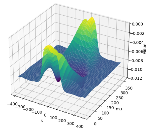
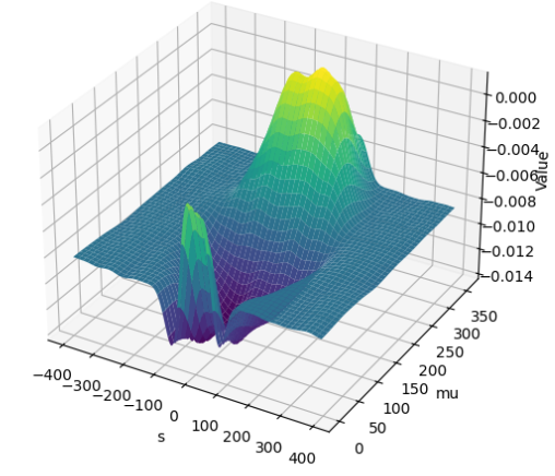
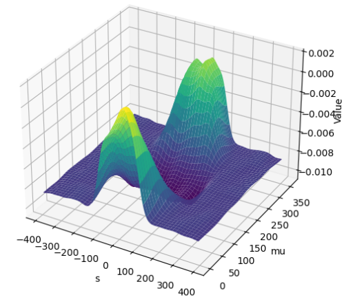
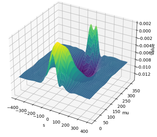
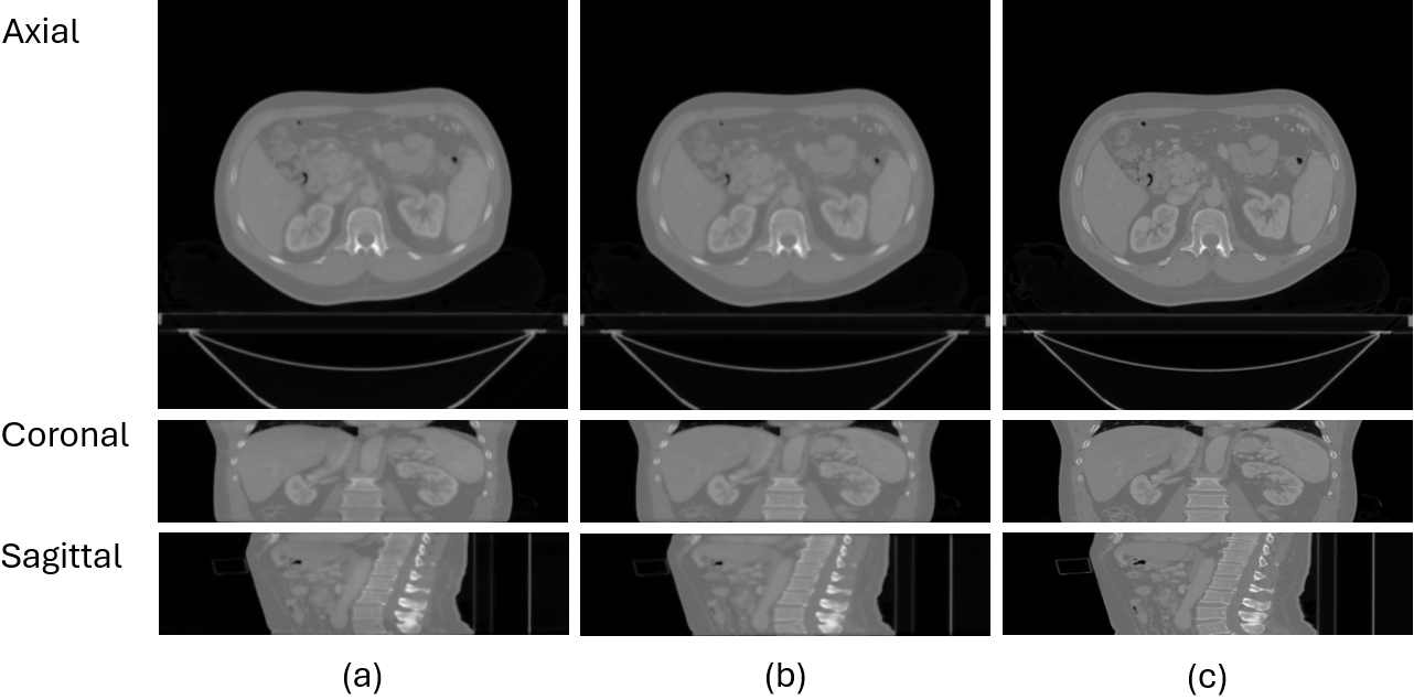
Table 4 illustrates that, in comparison to conventional AIR algorithms, our methodology demonstrates superior performance across a range of metrics, including MSE, SSIM, and PSNR. In particular, the method achieves a lower MSE, indicating a higher level of accuracy, and shows improved SSIM and PSNR, reflecting an enhanced fidelity and image quality. Moreover, the times indicated in the table represent the reconstruction duration on an NVIDIA 4080 Super GPU. This demonstrates that our approach after training significantly outperforms conventional AIR algorithm in terms of reconstruction speed.
| MSE | PSNR (dB) | SSIM | Time (s) | |
|---|---|---|---|---|
| Our | 0.0904 ± 0.0149 | 37.20± 1.34 | 0.9591±0.0051 | 4.5 |
| AIR(300) | 0.1472± 0.0827 | 34.55± 4.11 | 0.9131±0.0527 | 197 |
Figure 11 presents the reconstructed volume obtained with learned parameters. A comparison of the results obtained from the AIR algorithm with the ground truth demonstrates that the differentiable shift-variant FBP model is an effective method for preserving reconstruction details while maintaining structural accuracy.
4.3 Circle Plus Arc Orbit
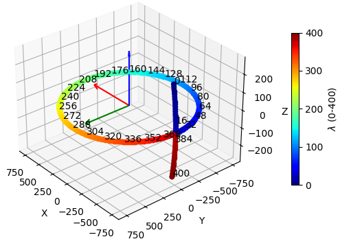
Another common non-circular orbit is the ”Circle Plus Arc Orbit”, as illustrated in Figure 12. This orbit combines a circle path with a small orthogonal arc. This orbit fulfills Tuy’s data sufficiency condition, effectively addressing the issue of decreased reconstruction accuracy at locations distant from the central transverse plane when the cone angle is considerable.
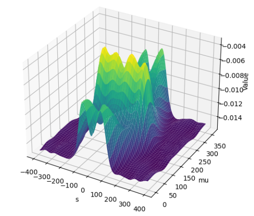
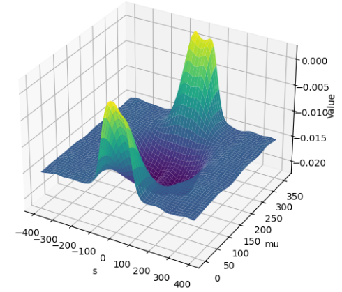
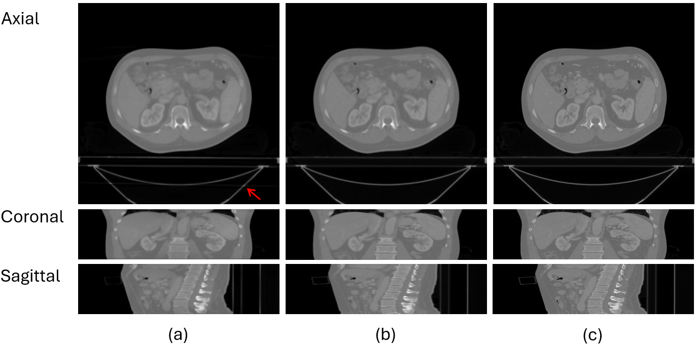
A learning rate of and training for epochs resulted in successful convergence of the network. Figure 13 depicts the learned redundancy weights obtained through the training process. It is evident that the projection data requires a fundamentally different redundancy weight when the source is on the circle than when the source is on the arc. These learned weights were then employed for reconstruction and compared with the results from iterative reconstruction and the ground truth. The reconstruction results, visualised using central slices, are presented in Figure 14.
Although the overall reconstruction quality is satisfactory, it is evident that there are some artifacts present at the location indicated by the red arrow in the central slice of the axial direction. Additionally, there is slight blurring visible in some regions. The aforementioned artifacts and blurring are caused by the discontinuities that occur at the endpoints of the trajectory, given that the trajectory is not closed.
As in Sections 4.1 and 4.2, the quality of the reconstructed volumes was assessed using MSE, PSNR, and SSIM as shown in Table 5. The results demonstrate that all evaluation metrics performed exceptionally well, indicating that suitable redundancy weights can be effectively learned based on the Circle Plus Arc Orbit.
| MSE | PSNR (dB) | SSIM | Time (s) | |
|---|---|---|---|---|
| Our | 0.1075 ± 0.0185 | 35.71± 1.49 | 0.9339±0.0055 | 4.5 |
| AIR(300) | 0.1360± 0.0565 | 34.41± 2.53 | 0.9216±0.0365 | 190 |
4.4 Random Nearest Neighbor Orbit
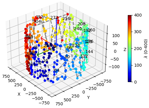
In order to further explore the potential of our model, we designed a geometric configuration with extremely complex trajectory. This trajectory is based on a spherical surface, with the assumption that the scanned object is located at the center of the sphere. As a consequence of the physical and geometric constraints inherent to the robotic C-arm CT system, the source points are constrained to a particular surface area near the middle plane of the sphere. Within this selected surface area, 400 source points were randomly sampled and distributed uniformly across the surface. This allows X-rays to effectively cover the scanned object from multiple angles, thereby providing ample data support for reconstruction. Specifically, based on Equation (15), the angle is randomly selected from a uniform distribution within the range of to , while the angle is uniformly selected from a tilt angle range of . Finally, starting from the first point, we apply the nearest neighbor algorithm to reorder these points into a trajectory, as illustrated in Figure 15.
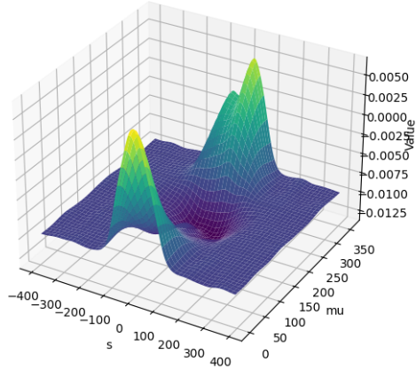
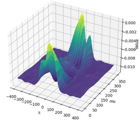
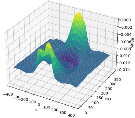
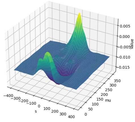
A learning rate of was applied, and the network was trained for a total of 394 epochs, resulting in successful convergence. The learned redundancy weights obtained from this training are illustrated in Figure 16.
| MSE | PSNR (dB) | SSIM | Time (s) | |
|---|---|---|---|---|
| Our | 0.1035 ± 0.0175 | 36.03± 1.23 | 0.9232±0.0062 | 4.5 |
| AIR(300) | 0.1348± 0.0514 | 34.30± 2.07 | 0.9150±0.0322 | 191 |
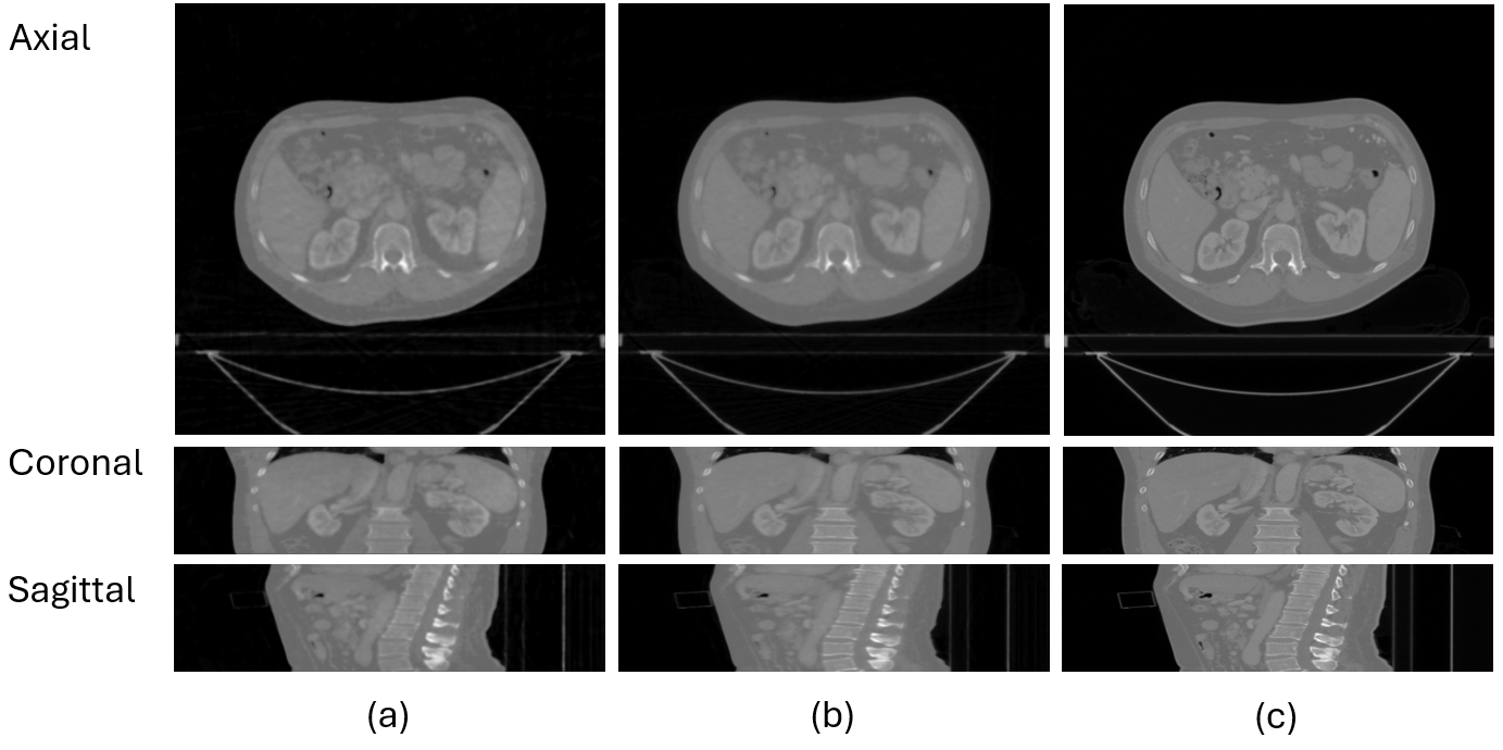
The trained weights were subsequently employed for image reconstruction. To evaluate the efficacy of the reconstruction process, we employed a series of quantitative metrics, including MSE, PSNR, and SSIM, as detailed in Table 6. The analysis indicates that the reconstructed results achieved satisfactory performance across the specified metrics. Nevertheless, an examination of the central slices of the reconstructed volume in Figure 17 reveals the presence of artifacts in the axial view.
The reason is that, given the complexity of the trajectory, the structural complexity of the required redundancy weights must also increase accordingly. However, in the case of discrete data, it is essential that the variation of the redundancy weights be as smooth as possible; otherwise, the introduction of artifacts may result. The neural network is only capable of balancing fidelity and smoothness within the constraints of the optimisation objective.
5 Discussions
In the reconstruction of arbitrary orbits, the differentiable shift-variant FBP neural network markedly accelerates the reconstruction process in comparison to traditional iterative algorithms. However, the generation of new simulated datasets and the retraining of the neural network are required for each new orbit geometry, which represents an additional overhead when the orbit changes frequently.
In comparison to analytical solutions, our method is capable of providing approximate solutions when the orbit is discontinuous, although some artifacts may be observed. Furthermore, our data-driven approach is able to automatically estimate the optimal redundancy weights for reconstruction based on the complexity of the orbit and the optimization objectives. This feature enables our method to potentially optimize based on other imaging effects, such as noise suppression, reduction of metal artifacts, or addressing limited view issues.
6 Conclusion
This research propose a differentiable shift-variant FBP neural network designed for arbitrary CBCT orbits reconstruction using known operator learning.
The findings of this study indicate that the differentiable shift-variant FBP neural network is capable of learning the requisite parameters for reconstruction based on projection data with circular, sinusoidal, circle plus arc orbit geometry, and random nearest neighbor orbit, and it consistently demonstrates robust performance in these reconstruction tasks. The results demonstrate that deep learning technology can effectively resolve the estimation of redundancy weight in the shift-variant FBP algorithm, making a valuable contribution to the field of CBCT reconstruction for non-circular orbits.
The practical implications of this research lie in the potential development of a novel approach to robotic C-arm CT imaging technology. This approach could enable the rapid reconstruction of data with customized orbits. This improvement would represent a significant advancement in the field of medical imaging, particularly in robotic C-arm CT imaging technology.
Future research will concentrate on further reducing the number of neural network parameters and developing rapid reconstruction algorithms for multi-orbit reconstruction based on this approach. Furthermore, more sophisticated deep learning techniques will be investigated to address artifacts resulting from the discontinuities of the orbit.
7 Acknowledgments
The authors gratefully acknowledge the scientific support and HPC resources provided by the Erlangen National High Performance Computing Center (NHR@FAU) of the FAU Erlangen-Nürnberg.
8 References
References
- [1] Linda-Sophie Schneider, Mareike Thies, Richard Schielein, Christopher Syben, Mathias Unberath, and Andreas Maier. Learning-based trajectory optimization for a twin robotic ct system. 2022.
- [2] Linda-Sophie Schneider, Mareike Thies, Christopher Syben, Richard Schielein, Mathias Unberath, and Andreas Maier. Task-based generation of optimized projection sets using differentiable ranking. 17th International Meeting on Fully Three-Dimensional Image Reconstruction in Radiology and Nuclear Medicine (Fully3D), 2023.
- [3] Gabriel Herl, Jochen Hiller, and Andreas Maier. Scanning trajectory optimisation using a quantitative tuybased local quality estimation for robot-based x-ray computed tomography. Nondestructive Testing and Evaluation, 35(3):287–303, 2020.
- [4] Gengsheng Lawrence Zeng. Medical image reconstruction, volume 530. Springer, 2010.
- [5] Lu Liu. Model-based iterative reconstruction: a promising algorithm for today’s computed tomography imaging. Journal of Medical imaging and Radiation sciences, 45(2):131–136, 2014.
- [6] Lennart R Koetzier, Domenico Mastrodicasa, Timothy P Szczykutowicz, Niels R van der Werf, Adam S Wang, Veit Sandfort, Aart J van der Molen, Dominik Fleischmann, and Martin J Willemink. Deep learning image reconstruction for ct: technical principles and clinical prospects. Radiology, 306(3):e221257, 2023.
- [7] Satoshi Kawata and Orhan Nalcioglu. Constrained iterative reconstruction by the conjugate gradient method. IEEE transactions on medical imaging, 4(2):65–71, 1985.
- [8] Xianglong Liu and Ying Wang. An improved conjugate gradient image reconstruction algorithm for electromagnetic tomography. Sensing and Imaging, 23(1):5, 2022.
- [9] Pierre Grangeat. Mathematical framework of cone beam 3d reconstruction via the first derivative of the radon transform. In Mathematical Methods in Tomography: Proceedings of a Conference held in Oberwolfach, Germany, 5–11 June, 1990, pages 66–97. Springer, 1991.
- [10] Michel Defrise and Rolf Clack. A cone-beam reconstruction algorithm using shift-variant filtering and cone-beam backprojection. IEEE transactions on medical imaging, 13(1):186–195, 1994.
- [11] Andreas K Maier, Christopher Syben, Bernhard Stimpel, Tobias Würfl, Mathis Hoffmann, Frank Schebesch, Weilin Fu, Leonid Mill, Lasse Kling, and Silke Christiansen. Learning with known operators reduces maximum error bounds. Nature machine intelligence, 1(8):373–380, 2019.
- [12] Yipeng Sun, Linda-Sophie Schneider, Fuxin Fan, Mareike Thies, Mingxuan Gu, Siyuan Mei, Yuzhong Zhou, Siming Bayer, and Andreas Maier. Data-driven filter design in fbp: Transforming ct reconstruction with trainable fourier series. 8th International Conference on Image Formation in X-Ray Computed Tomography, 2024.
- [13] Chengze Ye, Linda-Sophie Schneider, Yipeng Sun, and Andreas Maier. Deep learning computed tomography based on the defrise and clack algorithm. 8th International Conference on Image Formation in X-Ray Computed Tomography, 2024.
- [14] Christopher Syben, Markus Michen, Bernhard Stimpel, Stephan Seitz, Stefan Ploner, and Andreas K Maier. Pyro-nn: Python reconstruction operators in neural networks. Medical physics, 46(11):5110–5115, 2019.
- [15] Leslie N Smith. A disciplined approach to neural network hyper-parameters: Part 1–learning rate, batch size, momentum, and weight decay. arXiv preprint arXiv:1803.09820, 2018.
- [16] J Hong, M Reyngold, C Crane, J Cuaron, C Hajj, J Mann, M Zinovoy, E Yorke, E LoCastro, AP Apte, et al. Breath-hold ct and cone-beam ct images with expert manual organ-at-risk segmentations from radiation treatments of locally advanced pancreatic cancer [data set]. the cancer imaging archive. The Cancer Imaging Archive https://doi. org/10.7937/TCIA. ESHQ-4D90, 2021.
- [17] Grace J Gang, Tom Russ, Yiqun Ma, Christian Toennes, Jeffrey H Siewerdsen, Lothar R Schad, and J Webster Stayman. Metal-tolerant noncircular orbit design and implementation on robotic c-arm systems. In Conference proceedings. International Conference on Image Formation in X-Ray Computed Tomography, volume 2020, page 400. NIH Public Access, 2020.