X-ray free-electron lasing in a flying-focus undulator
Abstract
Laser-driven free-electron lasers (LDFELs) replace magnetostatic undulators with the electromagnetic fields of a laser pulse. Because the undulator period is half the wavelength of the laser pulse, LDFELs can amplify x rays using lower electron energies and over shorter interaction lengths than a conventional free-electron laser. Here we show that a flying-focus pulse substantially reduces the energy required to reach high gain in an LDFEL by providing a highly uniform, high-intensity field over the entire interaction length. The flying-focus pulse features an intensity peak that travels in the opposite direction of its phase fronts. This enables an LDFEL configuration where an electron beam collides head-on with the phase fronts and experiences a near-constant undulator strength as it co-propagates with the intensity peak. Three-dimensional simulations of this configuration demonstrate the generation of megawatts of coherent x-ray radiation with 20 less energy than a conventional laser pulse.
Introduction
Sources of coherent x rays are vital to medical, engineering, and basic scientific research. Coherent x rays allow for phase-contrast and diffractive imaging of molecules, cells, high-energy-density materials, and structural defects[1, 2, 3, 4, 5]; absorption spectroscopy and Thomson scattering to probe the structure and evolution of matter across phase changes[6, 7, 8, 9]; and the exploration and observation of quantum-electrodynamical processes, such as pair-production, photon–photon scattering, and vacuum birefringence[10, 11, 12, 13, 14, 15]. The most-brilliant coherent sources reside at large-scale accelerator facilities, where high-energy electron beams fired into a magnetostatic undulator produce x rays through the process of free-electron lasing. Despite the remarkable advances afforded by these facilities, broadening access to x-ray free electron lasers (FELs) would further accelerate scientific progress. A scientific path to broadening access—as opposed to simply building more large-scale accelerator facilities—is to shrink the undulator period. A shorter undulator period reduces the electron energy needed to generate x-ray wavelengths and the distance required for amplification to high powers. To accomplish this, magnetostatic undulators can be replaced by the electromagnetic fields of a laser pulse, where the undulator period is half the laser wavelength and only micrometers in scale compared to centimeters [16, 17, 18, 19, 20, 21, 22, 23, 24]. Coupled with the ability to self-seed, these “laser-driven” free-electron lasers (LDFELs) have the potential to bring coherent x-ray sources to numerous laser facilities without the need for a coherent seed, a long accelerator, or a large undulator.
Figure 1a illustrates a typical LDFEL configuration. A relativistic electron beam collides head-on with the phase fronts of a laser pulse. As the electrons oscillate in the fields of the pulse, they initially undergo inverse Compton scattering and emit incoherent radiation near the wavelength , where is the wavelength of the laser pulse, is the amplitude of its vector potential normalized to , is the initial electron energy normalized to , and is the initial electron velocity. The noise from the incoherent emission seeds a positive feedback loop where the radiation facilitates densification or “microbunching” of the electron beam at the length scale . The microbunching in turn enhances the emission, leading to exponential growth of coherent radiation near . The electron trajectories and radiation properties are similar to those in a conventional magnetostatic FEL with an undulator period and strength [20]. The length of the radiation source, however, is highly compressed. For a fixed radiation wavelength , the distance over which the power increases by a factor of , or gain length, is . Thus, the shortened undulator period—now on the order of microns instead of centimeters—allows for amplification over dramatically shorter distances and the use of significantly lower electron energies.
Despite these advantages, LDFELs face challenges that have, to date, impeded their experimental realization. Foremost among these is that the FEL parameter of an LDFEL is much smaller than that of a typical magnetostatic FEL. The FEL parameter quantifies the power efficiency, required electron beam quality, and gain bandwidth at saturation. Specifically, , where is the maximum normalized vector potential of the laser pulse, , is the electron beam current, and is the minimum RMS electron beam radius[20]. For typical LDFEL parameters, , which places stringent conditions on the normalized emittance , energy spread , and detuning needed for high gain at a target wavelength . Satisfying the detuning condition is particularly difficult in an LDFEL because of the spatially varying vector potential: , where is the path of an electron through the undulator. For a conventional laser pulse, this spatial variation is unavoidable. The pulse must be focused to achieve the undulator strengths necessary for high-power x-ray radiation, which introduces both transverse and longitudinal variation (Fig. 1a). While the spatial uniformity can be improved by increasing the focused spot size (Rayleigh range) with a concomittant increase in the duration, this approach quickly becomes impractical, leading to infeasibly large laser pulse energies for the distances needed to reach peak power, i.e., the saturation length .
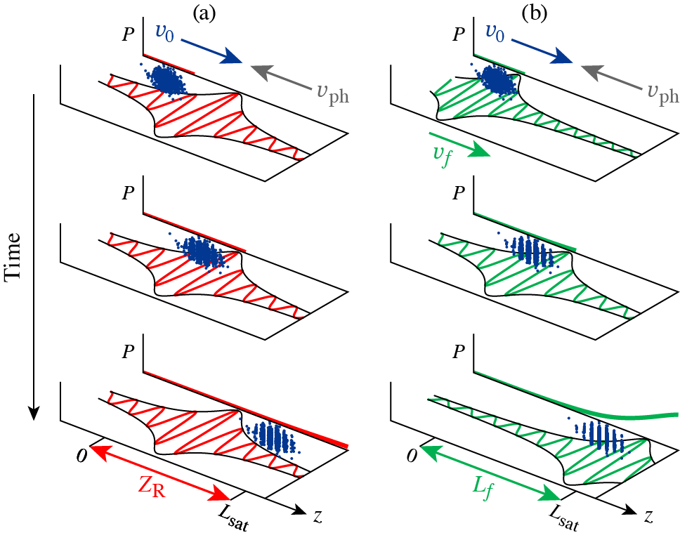
Here we demonstrate that “flying-focus” pulses can provide a highly uniform undulator for significantly less laser energy than a conventional laser pulse, enabling the generation of high-power, narrow-bandwidth x-ray radiation. The flying focus refers to a variety of optical techniques for creating a laser pulse with a time-dependent focal point [25, 26, 27, 28, 29, 30, 31, 32, 33]. The intensity peak formed by the moving focus travels a distance () far greater than a Rayleigh range while maintaining a near-constant profile. The LDFEL design introduced here employs the ideal flying focus, which creates a moving focal point by focusing a laser pulse through a lens with a time-dependent focal length [30, 31]. Within the focal range , The velocity of the resulting intensity peak can be made to travel at in the opposite direction of the phase fronts and in the same direction as the electron beam (Fig. 1b). The electrons, both colocated and cotraveling with the intensity peak, experience a nearly uniform undulator strength across the entire interaction length . To compare the x-ray radiation driven by flying focus and conventional pulses, the 3D FEL code GENESIS-1.3 [34] was modified to model LDFELs. Simulations employing this code show that with a electron beam, a flying-focus undulator can produce 1 MW of nm x-ray radiation in only a 1 cm interaction length using less energy than a conventional laser pulse. Such a source would allow for interrogation of warm dense matter [35, 36, 37] and falls within the “water-window”, making it an effective probe for biological matter [38, 39, 40].
Results
For a conventional laser pulse focused by an ideal lens, the transverse and longitudinal uniformity of the amplitude are characterized by the focused spot size and Rayleigh range (Fig. 1a). To avoid spatial detuning and ensure amplification to high powers, the Rayleigh range must be longer than the interaction length and the pulse duration sustained over the interaction time . As a result, the energy of a conventional laser undulator scales quadratically with the interaction length, where has been used. For a flying-focus pulse with an intensity peak that cotravels with the electron beam (), the transverse and longitudinal uniformity are characterized by the focused spot size and focal range (Fig. 1b). In this case, the longitudinal uniformity is decoupled from the focused spot size, i.e., does not depend on . Thus, the energy of a flying-focus undulator scales linearly with the interaction length. The ratio of energies needed to drive an LDFEL with fixed FEL parameter and radiation wavelength is then given by
| (1) |
The factor is determined by the power ratio of a flying-focus pulse with an arbitrary transverse profile to one with a Gaussian profile of spot size , both with the same maximum vector potential .
Equation (1) elucidates the advantage of using a flying focus to decouple the interaction length from the Rayleigh range. The ratio shows that a flying-focus pulse requires less energy than a conventional pulse in LDFEL configurations for which . When amplifying to saturation, the left-hand side of this condition is determined by the saturation length . Typical saturation lengths tend to be times larger than the gain length, i.e., , where . The right-hand side of the condition is determined by the electron beam radius . To ensure has sufficient transverse uniformity, the spot size of the flying focus should be larger than , i.e, , where . By combining these scalings and using the conservative approximation that , the condition can be reexpressed in terms of LDFEL parameters: , where the cold beam gain length has been used. This condition indicates that the advantage of flying-focus pulses is greater at longer laser wavelengths. For the parameters considered here m, cm, and mm, resulting in —a significant reduction in the required energy (Table 1). The use of longer laser wavelengths also allows for higher radiated powers and relaxes the requirements on the electron beam quality (see Discussion).
To demonstrate the advantages of an LDFEL with a flying-focus undulator, 3D, time-dependent simulations were conducted using the conventional FEL code GENESIS-1.3 [34]. The time-dependent model provided by GENESIS-1.3 allows for seeding from amplified spontaneous emission (SASE) and captures the evolution of the x-ray spectrum. This latter feature is critical for modeling an LDFEL because amplitude variations due to focusing and diffraction can shift the resonant frequency along the interaction length. Despite these features, GENESIS-1.3 was modified to better model an LDFEL. The equations of motion were updated to include the effects of the Gouy phase, phase-front curvature, plasma dispersion, the spatial profile of , and the transverse space-charge repulsion of the electron beam (see Methods).
| LDFEL parameters | |
|---|---|
| Target resonant wavelength (nm) | |
| Laser wavelength (m) | |
| Field amplitude/undulator strength | |
| FEL parameter | |
| 1D cold beam gain length (mm) | |
| Ideal saturation length (mm) | |
| Electron beam parameters | |
| Energy () | |
| Current (kA) | |
| Minimum RMS radius (m) | |
| Normalized emittance (m-rad) | |
| Energy spread | |
| Conventional Focus | |
| Transverse profile | Gaussian |
| Pulse duration (ps) | |
| Rayleigh range (cm) | , , |
| Spot size (m) | , , |
| Pulse energy (J) | , , |
| Flying Focus | |
| Transverse profile | Flattened Gaussian Beam[43] |
| Focal range (cm) | |
| Gaussian spot size at focus (m) | |
| Gaussian spot at lens (cm) | |
| Pulse energy (J) |
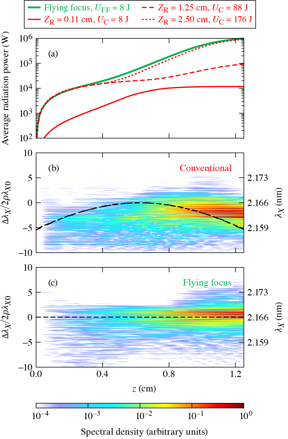
Figure 2 compares the evolution of the power and spectrum of (0.56 keV) x rays amplified in an LDFEL with either a flying-focus or conventional laser undulators. The parameters are displayed in Table 1. Consistent with the estimate above that , the flying-focus pulse required less energy than the conventional pulse to amplify the x rays to the saturated power . In this example, the nonideal effects of a spatially varying undulator strength were isolated from those of electron beam quality by initializing the beam with a negligible normalized emittance () and energy spread ().
The conventional laser undulator was able to mitigate spatial detuning and amplify the x rays to saturation with of energy, a Rayleigh range , and a corresponding spot size . At a more modest and , the saturated power was lower ( kW). With the same energy as the flying-focus undulator, i.e., and , the x-ray power increased rapidly as the electron beam approached the focal point ( cm) and encountered larger values of , but the radiation was mostly incoherent and microbunching was not observed. In each of these cases, the electron beam was initialized a distance before the focus to optimize the uniformity.
The flying-focus undulator mitigated spatial detuning and amplified the x rays to saturation with only of energy, a focal range , and a focused spot size . As opposed to the stationary focus of a conventional laser pulse, the intensity peak of the flying focus moves with the electron beam, ensuring that the electrons experience a nearly uniform and maximum undulator strength over the interaction length. The pulse had a flattened Gaussian transverse profile with (see Methods). This profile reduces transverse ponderomotive expulsion of the electron beam and provides transverse amplitude uniformity. The ability to use such a profile is a distinct advantage of the flying focus. With a conventional pulse, focusing and diffraction of a flattened intensity profile would exacerbate the spatial variations of . The near-propagation invariance of the flying focus guarantees that the flattened profile persists throughout the focal range.
Figure 2b illustrates how spatial inhomogeneities in the conventional laser undulator due to focusing and diffraction shift the resonant wavelength and modify the x-ray spectrum. Along the propagation axis (i.e., at ), the amplitude of the conventional pulse is given by , where the focal plane is located at . The resonant x-ray wavelength is then
| (2) |
where . Equation (2) shows that the resonant wavelength redshifts as the electron beam approaches the focus of the conventional pulse and then blueshifts as the beam moves away from the focus (dashed line in Fig. 2b). As affirmed by the dashed lines in Figs. 2b, the wavelength shift predicted by Eq. (2) is in agreement with the GENESIS-1.3 simulations. The net effect of the wavelength shifting is that conventional laser undulator does not achieve the maximum radiated power or minimum saturation length of an ideal, monochromatic plane-wave undulator ( MW and cm).
Figure 2c demonstrates that the longitudinal uniformity of the flying-focus undulator keeps the resonant wavelength tuned to target wavelength along the entire interaction length (dashed line in Fig. 2c). However, because the flying-focus pulse has a smaller spot size than the conventional pulse, its ponderomotive force causes a greater transverse expansion of the electron beam. As a result of the lower beam density, the flying-focus undulator also does not achieve the maximum radiated power or minimum saturation length of an ideal, monochromatic plane-wave undulator. Nevertheless, both the J flying-focus and conventional laser undulators produce high-power, narrowband x-ray radiation: at saturation, the standard deviation of both spectral energy densities is .
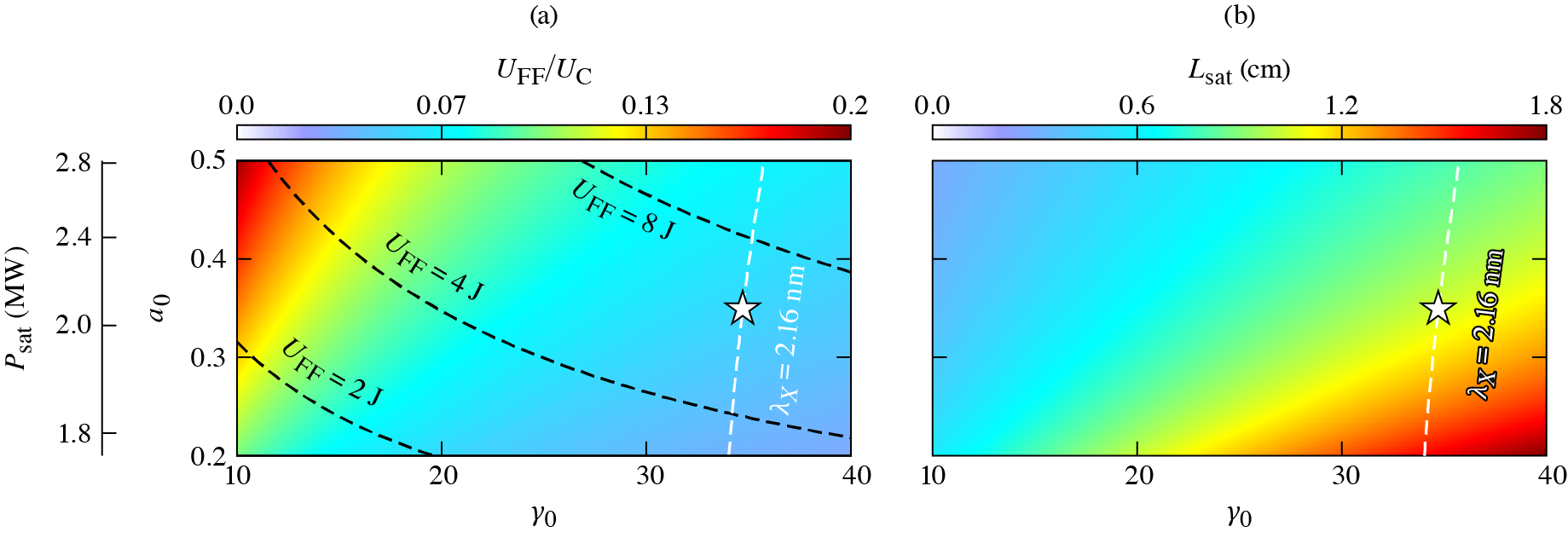
Figure 3 presents the energy-cost benefit of a flying-focus undulator within a broader LDFEL design space. The energy advantage of the flying focus increases (Fig. 3a) as the saturation length gets longer (Fig. 3b), or equivalently, as the target x-ray wavelength gets shorter. The energy ratio is calculated using Eq. (1) with m, the focal range of the flying focus set to , the Rayleigh range of the conventional pulse to , and the duration of both pulses to . Contours of constant wavelength are nearly vertical (e.g., the white dashed line), and the wavelength progressively gets shorter from left to right in each plot (). The minimum saturation length was calculated using Eq. (33) of Ref. 20 with the gain length corrected by an empirical factor determined by 3D GENESIS-1.3 simulations of an ideal plane-wave undulator, i.e, . The use of a plane wave results in a slightly lower energy needed to reach saturation when compared to pulses with transverse structure (cf. Fig. 2).
The range of values in Fig. 3 was selected to produce a high saturated power (left scale) while ensuring a linear interaction so that the radiation is predominately composed of a single harmonic at . The maximum achievable saturated power grows with the undulator amplitude but is independent of : , where is the classical electron radius and the empirical factor of 0.4 is determined by 3D GENESIS-1.3 simulations of a plane-wave undulator. Note that lower values of reduce the deleterious impact of spatial inhomogeneity on the conventional laser undulator [Eq. (2)]. The highest value of was chosen to avoid quantum effects, which increase the classical gain length by a factor , where is the quantum FEL parameter and is the Compton wavelength [17, 22]. For all interactions displayed in Fig. 3, .
While the flying focus decreases the laser energy required for a high-gain LDFEL, achieving the necessary electron beam quality remains a formidable challenge. For the parameters considered in Table 1, amplification to the maximum saturated power requires an energy spread and a normalized emittance m-rad. These requirements become even more demanding when attempting to lase at shorter x-ray wavelengths. When the electron beam does not satisfy these requirements, the number of electrons that contribute to the instability drops, which reduces the saturated power and elongates the gain length and saturation length [44, 20]. Thus, the combination of an imperfect beam and a sufficiently uniform undulator can greatly increase the laser-pulse energy needed for amplification to high powers.
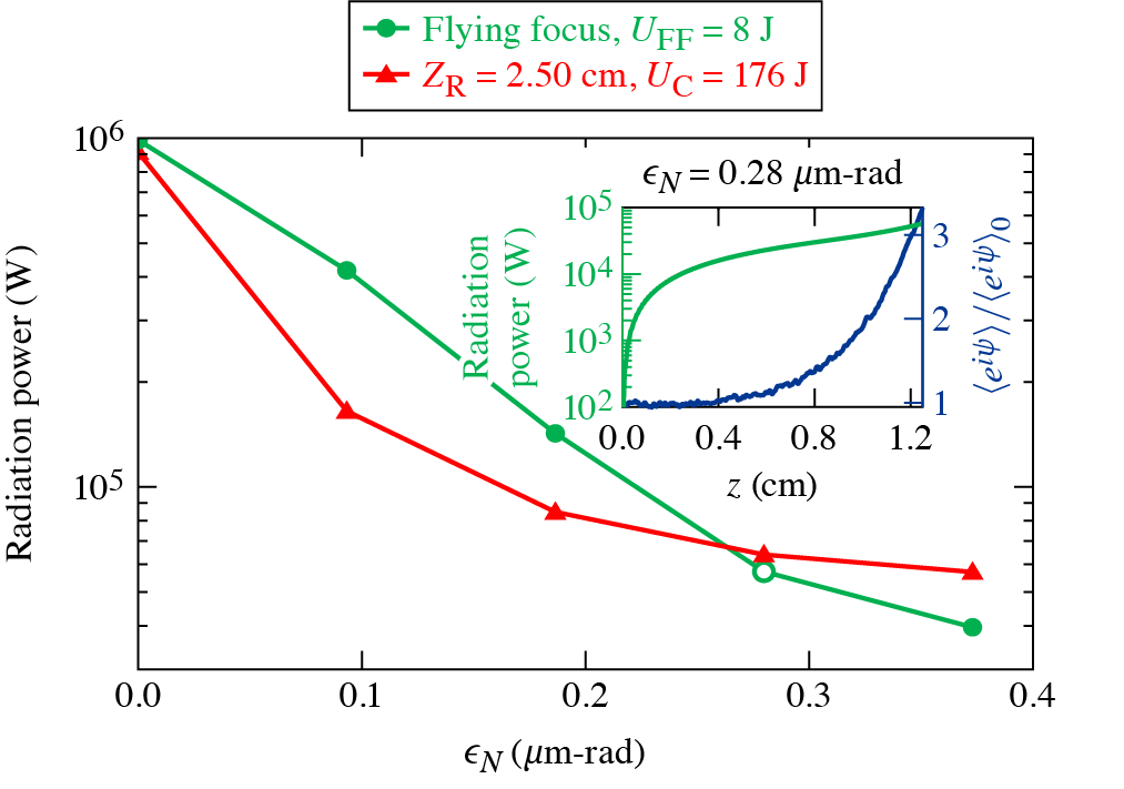
To assess the impact of imperfect electron beams on the x-ray power generated in the example design (Table 1 and star in Fig. 3), simulations were run with initial emittances ranging from to m-rad. Figure 4 displays the resulting x-ray powers at cm. For both the flying focus and conventional laser undulator, the x-ray power first drops as the initial emittance is increased from to m-rad and then plateaus to the incoherent power at emittances m-rad. At lower emittances, better amplitude uniformity makes the flying-focus undulator more resilient to the adverse effects of beam quality. At larger emittances, the x-ray power produced by the J conventional laser undulator is slightly greater than that of the J flying-focus undulator. This is because the flying-focus pulse has a smaller spot size: when , a larger portion of electrons have sufficient transverse momentum to laterally escape the fields of the flying-focus pulse. Of course, this can be remedied by increasing the spot size of the flying-focus pulse at the cost of more energy. Regardless, imperfect electron beams do not change the fact that the flying-focus pulse requires much less energy than the conventional pulse to obtain a comparable radiation power.
The inset in Fig. 4 shows the evolution of the radiated power and bunching factor through the flying-focus undulator for the electron beam with m-rad = . The bunching factor , where is the ponderomotive phase and denotes an average over all electrons, is normalized to its initial value at . While amplification of the x-ray power and exponential growth of the bunching factor are observed at this emittance, the maximum x-ray power is reduced by an order of magnitude compared to the ideal electron beam (). Note that amplification in the range m-rad m-rad violates the Pellegrini criterion for spatial overlap between the electron beam and x-ray pulse [45]. The criterion states that the distance over which the electron beam spreads transversely, i.e., , should be greater than the Rayleigh range of the x-ray pulse: m-rad. However, in an LDFEL, both and the x-ray Rayleigh range are longer than the saturation length. Thus, the electron beam remains spatially overlapped with the x-ray beam by virtue of the short saturation length. The next most stringent requirement on the emittance limits emittance-induced spectral broadening: [18, 21, 22]. This condition is consistent with the absence of amplification observed at m-rad, where the final bandwidth was much greater . Whether one opts for a flying-focus or conventional laser undulator, high-quality electron beams are critical for an experimental realization of an LDFEL that can produce high-power x-ray radiation.
Discussion
The ratio of energies expressed in Eq. (1) demonstrates that a flying-focus pulse decreases the energy needed for a uniform undulator when the interaction length exceeds the Rayleigh range. The appearance of in the denominator suggests that this benefit is reduced for shorter laser wavelengths and, by extension, shorter undulator periods. This is because for the same spot size, shorter-wavelength laser pulses have longer Rayleigh ranges, which provide better amplitude uniformity. Moreover, the gain and saturation lengths are smaller at shorter wavelengths, which means the interaction length is smaller. This suggests an even further reduction in the benefit of the flying focus at shorter wavelengths: . Nevertheless, an LDFEL designed for longer laser wavelengths and undulator periods has several advantages that incentivize working in a regime where the flying focus provides an energy savings.
The important parameters for designing an LDFEL are the FEL parameter , gain length , radiation power at saturation , electron beam energy , and quantum FEL parameter . Consider two undulator periods, and . For the same target x-ray wavelength, beam current, beam radius, and peak vector potential, the ratios of the design parameters are given by
| (3) |
The ratios in Eq. (3) demonstrate that undulators with longer periods have higher efficiencies, relax the requirements on the beam quality, result in higher saturated powers, and suffer less degradation due to quantum effects. Undulators with shorter periods, on the other hand, allow for smaller interaction lengths and lower electron energies. As an example, comparing a typical glass laser with m to a CO2 laser with m yields , , , , and . Aside from the advantages of longer undulator periods, imperfect electron beams and quantum effects can substantially increase the gain and interaction lengths, which may make the flying focus energetically favorable even when using shorter-wavelength lasers. This will be a topic of future investigation. Note that the ratios appearing in Eq. (3) can also be used to compare LDFELs to conventional magnetostatic FELs. The main advantages of LDFELs are the smaller distances required to reach saturation and the much lower electron energies needed for the same radiation wavelength.
In the flying focus configuration implemented here, the electron beam collides head-on with the phase fronts and cotravels with the moving intensity peak [Fig. 1(b)]. The velocity control and amplitude uniformity afforded by the flying focus allows for other interaction geometries as well. The ideal flying focus uses a lens with a time-dependent focal length to produce a focal point that moves longitudinally, either parallel or antiparallel to the phase fronts [30, 31]. With the addition of a time-dependent tilt, the focal point could move in both the transverse and longitudinal directions while the phase fronts move only in the longitudinal direction[46]. As before, the velocity of the focal point can be preset to , so that the electron beam cotravels with the intensity peak and experiences a uniform amplitude over an extended distance. This configuration complements that proposed in Ref. 21 and Ref. 47 where pulse-front tilt is used to ensure amplitude uniformity throughout the interaction. The difference is that with the flying focus the focal point moves with the electron beam. In both cases, the undulator period is increased from to , where is the angle between the electron velocity and the phase velocity of the laser pulse. The flexibility to adjust allows for optimization of the undulator period. Specifically, one can make the replacement in Eq. (3).
The use of the ideal flying focus was motivated by its conceptual simplicity. Other optical techniques could also be used to achieve the LDFEL configuration depicted in Fig. 1b. These include “Arbitrarily Structured Laser Pulses” (ASTRL pulses)[32] and the experimentally demonstrated “space-time wave packets” [48, 49] or “chromatic flying focus” [26, 29]. An LDFEL based on the “chromatic” flying focus was also simulated as a part of this study. The chromatic flying focus creates a moving focal point by focusing a chirped laser pulse with a chromatic lens. The chromatic lens focuses each frequency to a different location within an extended focal range, while the chirp determines the arrival time of each frequency at its focus. The simulations (not shown) revealed that the variation in the undulator period caused by the chirp can modify the x-ray spectrum and reduce the saturated power. Laser pulse propagation simulations of the chromatic flying focus, following the method outlined in Ref. 27, indicate that the focal geometry can be adjusted to reduce to chirp and achieve the same saturated power as the ideal flying focus. These modifications to the focal geometry require 37.5 J of laser energy to amplify the x-ray radiation to 1 MW in 1.25 cm compared to 176 J needed with a conventional laser pulse.
In conclusion, flying-focus pulses can substantially reduce the energy required to produce coherent, narrowband, high-power x-rays in a laser-driven free-electron laser. In contrast to the static focal point of a conventional laser pulse, the dynamic focal point of a flying-focus pulse travels with the electron beam, ensuring a uniform undulator over the entire interaction length. Simulations of a design based on CO2 laser parameters showed that a flying focus can produce 1 MW of nm x-ray radiation from a 17.5 MeV electron beam in a 1.25 cm interaction length using less energy than a conventional laser pulse. While electron beam quality does affect the final x-ray power, it does not change the fact that the flying focus provides an energy advantage. The velocity control and extended interaction lengths at high intensity enabled by the flying focus provide a path to LDFELs with currently achievable laser energies.
Methods
0.1 Laser-driven free-electron laser model
In a laser-driven free-electron laser (LDFEL), the electromagnetic field of a laser pulse with a wavelength provides an undulator that allows for the emission and amplification of electromagnetic fields at other wavelengths. The laser pulses considered here propagate in the negative direction and are circularly polarized. The electromagnetic fields of the pulses are modeled in terms of the vector potential
| (4) |
where , , is the plasma frequency, and potentials are normalized to throughout. The amplitudes and phases are real quantities and are defined in Section 0.2. A head-on collision between a relativistic electron beam and these fields results in the emission and amplification of a circularly polarized x-ray pulse (Fig. 1 and Table 1) that propagates in the positive direction. The electromagnetic fields of the x-ray pulse are modeled with the vector potential
| (5) |
where , , and is complex. The plasma dispersion contribution to is neglected because .
The motion of beam electrons in the laser and x-ray pulses can be separated into rapid and slowly varying components. The rapid motion describes the oscillations in the fields of the laser pulse, while the slow motion describes trajectory modifications due to ponderomotive forces and the space charge fields. The rapid oscillations modulate the slow “guiding-center” evolution of the positions and momenta. In the following, a tilde () is used to distinguish the rapidly varying momenta from the unadorned guiding-center momenta.
The rapidly varying momenta are equal to the local value of the laser-pulse vector potential: , where the momenta have been normalized by . The guiding-center dynamics are governed by the Hamiltonian
| (6) |
where
| (7) |
is the ponderomotive potential,
| (8) |
is the phase of the ponderomotive beat, and are the scalar and vector potentials describing the space-charge fields, and is the longitudinal canonical momentum. In general, , thus terms have been neglected in . The derivation of involves a cycle average over the period of the laser pulse in a frame moving with the electron beam (). The ponderomotive phase varies slowly in this frame because or, equivalently, .
The equations of motion for the guiding-center coordinates, momenta, and energy are derived from the Hamiltonian. The coordinates evolve according to
| (9) |
where . The transverse momenta evolve in response to the transverse ponderomotive and space-charge forces
| (10) |
Here, has been used to drop terms in the transverse ponderomotive force. The work done by the ponderomotive and space-charge forces modifies the electron energy
| (11) |
where has been used in the time derivative of and it has been assumed that . This latter condition is always satisfied for conventional laser pulses with flattop temporal profiles, such as those used in the simulations. For the flying-focus pulses of interest, where the intensity peak is colocated and cotravels with the electron beam, it is convenient to recast the condition in terms of the coherent x-ray power: . Evaluating the right-hand side with the parameters in Table 1 and m yields , which is easily satisfied.
In GENESIS-1.3, the equations of motion are integrated in instead of . With the substitution , the full set of guiding-center equations of motion becomes
| (12) | |||
| (13) | |||
| (14) | |||
| (15) | |||
| (16) |
where has been used in . This set of equations is similar to the set describing electron motion in a conventional magnetostatic FEL with an undulator period (cf. Ref. 50). There are, however, two important distinctions. First, the focusing geometry used for the laser pulse contributes a phase that can spatially detune the FEL instability [Eq. (15)]. Second, the transverse ponderomotive force [first term in Eq. (12)] pushes electrons from regions of high to low undulator strength. When the intensity of the laser pulse is peaked on-axis, this has the opposite effect of the natural focusing that occurs in a magnetostatic undulator.
The motion of the electron beam in the laser undulator results in a transverse current that drives the x-ray radiation. The envelope of the x-ray pulse evolves according to the paraxial wave equation
| (17) |
where is the classical electron radius and the summation is over all electrons. In practice, GENESIS-1.3 uses “macro”-electrons to avoid simulating all of the electrons present in an actual beam. To solve Eqs. (12)–(17), the macroelectrons are initialized in as “slices” of duration , where is the target radiation wavelength [34, 51]. The macroelectron motion and x-ray envelope are advanced in steps of . After a specified number of longitudinal steps , the envelope is advanced in time by . This numerical approach is valid when is much shorter than the cooperation length, , which defines the slippage of the x-ray pulse relative to the electron beam over a gain length. The underlying assumption is that the instability does not grow significantly in the time it takes the x-ray radiation to “slip” by one electron slice (i.e., by a length ).
The density and current of the electron beam also produce space-charge fields that feedback onto the motion. The and terms appearing in Eqs. (12) and (14) correspond to the Lorentz forces from the longitudinal and radial electric fields () and azimuthal magnetic field (, where ). The longitudinal electric field is assumed to be periodic with respect to the ponderomotive phase, i.e., , where the amplitudes () are real. Substitution of the Fourier series into the inhomogeneous wave equation provides an equation for each amplitude [52, 50]
| (18) |
where the summation is over all macroelectrons in a time slice. Within the summation, has been used to approximate and , where and are the charge and longitudinal current densities, respectively. The simulations presented above include the mode of the longitudinal electric field.
A laser-based undulator lowers the electron energy needed to produce x rays, but operating at lower energies exacerbates the effects of transverse space-charge repulsion. As a rough estimate, transverse space-charge forces will cause a significant increase in the electron beam radius over a length . For the presented design (Table 1), this length is comparable to the interaction length: cm and cm. To capture the effect of these forces, a self-consistent calculation of the transverse space-charge fields ( and ) and their feedback onto the electron motion was added to GENESIS-1.3. As with , and are assumed to be periodic with respect to the ponderomotive phase. Unlike , however, these field components are nonzero for . Assuming cylindrical symmetry, the amplitudes of the transverse space-charge fields satisfy
| (19) | ||||
| (20) |
The same approximations applied to the delta functions in Eq. (18) are applied here. In addition, the longitudinal velocity in the summation for is approximated by the initial velocity (), such that . Note that the term for the space-charge fields is the dominant contribution; the term is smaller.
One of the most-striking differences between conventional FEL and LDFEL simulations is the requirement on the transverse resolution. A series of simulations using the LDFEL-modified version of GENESIS-1.3 was conducted to determine the transverse resolution required for convergence of the saturated power and saturation length. For simplicity, an ideal, plane-wave laser undulator was considered. The simulations confirmed the analytic calculations in Ref. 20 that at a minimum it is necessary to resolve transverse wave numbers up to
| (21) |
Because the gain length () is much smaller in an LDFEL, the LDFEL simulations require a much higher transverse resolution to accurately model all of the amplified wavevectors: .
0.2 Laser pulse model
The amplitudes and phases of the conventional and flying-focus pulses used in the GENESIS-1.3 simulations are given by
| (22) | ||||
| (23) | ||||
| (24) | ||||
| (25) |
where is the longitudinal position of the electron beam with respect to the center of the interaction region. The expressions for the conventional pulse correspond to a laser pulse focused by an ideal lens in the Gaussian optics approximation with a focal plane at , spot size , radius of curvature , and Gouy phase . The focal plane was placed in the middle of the interaction region to (1) ensure the greatest amplitude uniformity, (2) provide the greatest average amplitude, and (3) allow the beam to radiate at all resonant wavelengths twice along its path (see Eq. (2) and Fig. 2b). The spatial variation in the phase had almost no effect on the amplification for the simulated spot sizes.
The amplitude and phase of the flying focus corresponds to a flattened Gaussian beam (FGB) of order [43]. An FGB is a linear combination of the zeroth- and first-order radial Laguerre–Gaussian modes. Because the electron beam is colocated with the moving focus and much shorter than the effective Rayleigh range [31], the and -dependence in the amplitude and phase of the FGB is and is therefore neglected in Eqs. (24) and (25). In addition, the phase has an extrema at in the moving focal plane. Thus, the associated term in Eq. (15), , is negligible. The results of simulations with either the full expression for or were identical. The NGB profile was chosen to weaken the transverse ponderomotive force on the electron beam. This can also be achieved by using orthogonally polarized Laguerre-Gaussian modes with different orbital angular momentum values [53, 54, 55].
Wave propagation simulations of a conventional laser pulse with an FGB profile (not presented) showed a substantial increase in the amplitude nonuniformity across the interaction length compared to a pure Gaussian profile. Interference between the modes of the FGB resulted in two on-axis peaks located symmetrically about the focus () with an intensity 1.3 larger than the intensity at focus. The interference also caused the flattopped transverse profile to rapidly degrade away from the focal plane. Due to the exacerbated amplitude variation and degradation in the flattop profile, the conventional FGB was observed to produce a lower x-ray power than a conventional pulse with a simple Gaussian profile but the same energy. The interference between modes also occurs for an FGB flying focus, but the location of the intensity peaks and degraded flattop profile are located relative to the moving focal plane. As a result, an electron beam colocated and cotraveling with the moving focus does not enter the regions of space where these effects are prominent.
The energies of a conventional and flying-focus pulse are given by
| (26) | ||||
| (27) |
where and are the radii of the electric fields at focus for a Gaussian transverse profile, is the pulse duration, and when the focal velocity [27, 31, 56]. The pulse duration necessary to sustain the undulator over the interaction length is . For the simulated interaction, cm, yielding ps as displayed in Table 1. A pure Gaussian transverse profile has an , while an FGB has [Eq. (24)]. The radius of the electric field for the full FGB profile at focus is 1.5 or m.
References
- [1] Wilkins, S., Gureyev, T. E., Gao, D., Pogany, A. & Stevenson, A. Phase-contrast imaging using polychromatic hard x-rays. \JournalTitleNature 384, 335–338 (1996).
- [2] Pfeiffer, F., Weitkamp, T., Bunk, O. & David, C. Phase retrieval and differential phase-contrast imaging with low-brilliance x-ray sources. \JournalTitleNature Physics 2, 258–261, DOI: 10.1038/nphys265 (2006).
- [3] Barty, A. et al. Ultrafast single-shot diffraction imaging of nanoscale dynamics. \JournalTitleNature Photonics 2, 415–419, DOI: 10.1038/nphoton.2008.128 (2008).
- [4] Robinson, I. & Harder, R. Coherent x-ray diffraction imaging of strain at the nanoscale. \JournalTitleNature materials 8, 291–298 (2009).
- [5] Miao, J., Ishikawa, T., Robinson, I. K. & Murnane, M. M. Beyond crystallography: Diffractive imaging using coherent x-ray light sources. \JournalTitleScience 348, 530–535 (2015).
- [6] Glenzer, S. H. & Redmer, R. X-ray Thomson scattering in high energy density plasmas. \JournalTitleReviews of Modern Physics 81, 1625–1663 (2009).
- [7] Yano, J. & Yachandra, V. K. X-ray absorption spectroscopy. \JournalTitlePhotosynthesis research 102, 241–254 (2009).
- [8] Ciricosta, O. et al. Direct measurements of the ionization potential depression in a dense plasma. \JournalTitlePhysical review letters 109, 065002 (2012).
- [9] Vinko, S. et al. Creation and diagnosis of a solid-density plasma with an x-ray free-electron laser. \JournalTitleNature 482, 59–62 (2012).
- [10] Ringwald, A. Pair production from vacuum at the focus of an x-ray free electron laser. \JournalTitlePhysics Letters B 510, 107–116 (2001).
- [11] Heinzl, T. et al. On the observation of vacuum birefringence. \JournalTitleOptics communications 267, 318–321 (2006).
- [12] Di Piazza, A., Müller, C., Hatsagortsyan, K. Z. & Keitel, C. H. Extremely high-intensity laser interactions with fundamental quantum systems. \JournalTitleRev. Mod. Phys. 84, 1177–1228, DOI: 10.1103/RevModPhys.84.1177 (2012).
- [13] Gonoskov, A., Blackburn, T., Marklund, M. & Bulanov, S. Charged particle motion and radiation in strong electromagnetic fields. \JournalTitleReviews of Modern Physics 94, 045001 (2022).
- [14] Fedotov, A. et al. Advances in QED with intense background fields. \JournalTitlePhysics Reports 1010, 1–138 (2023).
- [15] Macleod, A., Edwards, J., Heinzl, T., King, B. & Bulanov, S. Strong-field vacuum polarisation with high energy lasers. \JournalTitleNew Journal of Physics 25, 093002 (2023).
- [16] Gallardo, J. C., Fernow, R. C., Palmer, R. & Pellegrini, C. Theory of a free-electron laser with a gaussian optical undulator. \JournalTitleIEEE journal of quantum electronics 24, 1557–1566 (1988).
- [17] Bonifacio, R. Quantum SASE FEL with laser wiggler. \JournalTitleNuclear Instruments and Methods in Physics Research Section A: Accelerators, Spectrometers, Detectors and Associated Equipment 546, 634–638 (2005).
- [18] Bacci, A., Ferrario, M., Maroli, C., Petrillo, V. & Serafini, L. Transverse effects in the production of x rays with a free-electron laser based on an optical undulator. \JournalTitlePhysical Review Special Topics-Accelerators and beams 9, 060704 (2006).
- [19] Bacci, A. et al. Compact x-ray free-electron laser based on an optical undulator. \JournalTitleNuclear Instruments and Methods in Physics Research Section A: Accelerators, Spectrometers, Detectors and Associated Equipment 587, 388–397 (2008).
- [20] Sprangle, P., Hafizi, B. & Peñano, J. R. Laser-pumped coherent x-ray free-electron laser. \JournalTitlePhys. Rev. ST Accel. Beams 12, 050702, DOI: 10.1103/PhysRevSTAB.12.050702 (2009).
- [21] Steiniger, K. et al. Optical free-electron lasers with traveling-wave Thomson-scattering. \JournalTitleJournal of Physics B: Atomic, Molecular and Optical Physics 47, 234011 (2014).
- [22] Bonifacio, R., Fares, H., Ferrario, M., McNeil, B. W. & Robb, G. R. Design of sub-angstrom compact free-electron laser source. \JournalTitleOptics Communications 382, 58–63 (2017).
- [23] Graves, W. The CXFEL project at Arizona State University. In Proceedings of the 67th ICFA Adv. Beam Dyn. Workshop Future Light Sources, Luzern, Switzerland, 54–57 (2023).
- [24] Xu, X. et al. Attosecond x-ray free-electron lasers utilizing an optical undulator in a self-selection regime. \JournalTitlePhysical Review Accelerators and Beams 27, 011301 (2024).
- [25] Sainte-Marie, A., Gobert, O. & Quere, F. Controlling the velocity of ultrashort light pulses in vacuum through spatio-temporal couplings. \JournalTitleOptica 4, 1298–1304 (2017).
- [26] Froula, D. H. et al. Spatiotemporal control of laser intensity. \JournalTitleNature photonics 12, 262–265 (2018).
- [27] Palastro, J. P. et al. Ionization waves of arbitrary velocity driven by a flying focus. \JournalTitlePhysical Review A 97, 033835 (2018).
- [28] Palastro, J. P. et al. Dephasingless laser wakefield acceleration. \JournalTitlePhysical review letters 124, 134802 (2020).
- [29] Jolly, S. W., Gobert, O., Jeandet, A. & Quéré, F. Controlling the velocity of a femtosecond laser pulse using refractive lenses. \JournalTitleOptics express 28, 4888–4897 (2020).
- [30] Simpson, T. T. et al. Spatiotemporal control of laser intensity through cross-phase modulation. \JournalTitleOptics Express 30, 9878–9891 (2022).
- [31] Ramsey, D. et al. Exact solutions for the electromagnetic fields of a flying focus. \JournalTitlePhysical Review A 107, 013513 (2023).
- [32] Pierce, J. R. et al. Arbitrarily structured laser pulses. \JournalTitlePhys. Rev. Res. 5, 013085, DOI: 10.1103/PhysRevResearch.5.013085 (2023).
- [33] Pigeon, J. J. et al. Ultrabroadband flying-focus using an axiparabola-echelon pair. \JournalTitleOpt. Express 32, 576–585, DOI: 10.1364/OE.506112 (2024).
- [34] Reiche, S. Genesis 1.3: A fully 3D time-dependent FEL simulation code. \JournalTitleNuclear Instruments and Methods in Physics Research Section A: Accelerators, Spectrometers, Detectors and Associated Equipment 429, 243–248 (1999).
- [35] Hau-Riege, S. P., London, R. A., Chapman, H. N. & Bergh, M. Soft-x-ray free-electron-laser interaction with materials. \JournalTitlePhys. Rev. E 76, 046403, DOI: 10.1103/PhysRevE.76.046403 (2007).
- [36] Mahieu, B. et al. Probing warm dense matter using femtosecond x-ray absorption spectroscopy with a laser-produced betatron source. \JournalTitleNature Communications 9, 3276, DOI: 10.1038/s41467-018-05791-4 (2018).
- [37] Falk, K. Experimental methods for warm dense matter research. \JournalTitleHigh Power Laser Science and Engineering 6, e59, DOI: 10.1017/hpl.2018.53 (2018).
- [38] Spielmann, C. et al. Generation of coherent x-rays in the water window using 5-femtosecond laser pulses. \JournalTitleScience 278, 661–664 (1997).
- [39] Berglund, Rymell, Peuker, Wilhein & Hertz. Compact water-window transmission x-ray microscopy. \JournalTitleJournal of microscopy 197, 268–273 (2000).
- [40] Pertot, Y. et al. Time-resolved x-ray absorption spectroscopy with a water window high-harmonic source. \JournalTitleScience 355, 264–267 (2017).
- [41] Polyanskiy, M. 9.3 microns: Toward a next-generation CO2 laser for particle accelerators. Tech. Rep., Brookhaven National Laboratory (BNL), Upton, NY (United States) (2022).
- [42] https://www.bnl.gov/atf/capabilities/laser-systems.php. Accessed: 2024-08-30.
- [43] Gori, F. Flattened Gaussian beams. \JournalTitleOptics Communications 107, 335–341 (1994).
- [44] Freund, H. P. & Antonsen, T. M. Principles of free-electron lasers (Springer, 1992).
- [45] Pellegrini, C. Progress toward a soft x-ray fel. \JournalTitleNuclear Instruments and Methods in Physics Research Section A: Accelerators, Spectrometers, Detectors and Associated Equipment 272, 364–367 (1988).
- [46] Gong, Z., Cao, S., Palastro, J. P. & Edwards, M. R. Laser wakefield acceleration of ions with a transverse flying focus. \JournalTitlearXiv preprint arXiv:2405.02690 (2024).
- [47] Debus, A. D. et al. Traveling-wave Thomson scattering and optical undulators for high-yield EUV and X-ray sources. \JournalTitleApplied Physics B 100, 61–76, DOI: 10.1007/s00340-010-3990-1 (2010).
- [48] Kondakci, H. & Abouraddy, A. F. Optical space-time wave packets having arbitrary group velocities in free space. \JournalTitleNature communications 10, 1–8 (2019).
- [49] Yessenov, M. et al. Space-time wave packets localized in all dimensions. \JournalTitleNature Communications 13, 4573 (2022).
- [50] Reiche, S. Numerical studies for a single pass high gain free-electron laser. Ph.D. thesis, DESY (2000).
- [51] Reiche, S., Musumeci, P. & Goldammer, K. Recent upgrade to the free-electron laser code Genesis 1.3. In 2007 IEEE Particle Accelerator Conference (PAC), 1269–1271 (IEEE, 2007).
- [52] Tran, T.-M. & Wurtele, J. Review of free-electron-laser (FEL) simulation techniques. \JournalTitleComputer Physics Reports (1990).
- [53] Ramsey, D., Franke, P., Simpson, T., Froula, D. & Palastro, J. Vacuum acceleration of electrons in a dynamic laser pulse. \JournalTitlePhysical Review E 102, 043207 (2020).
- [54] Ramsey, D. et al. Nonlinear Thomson scattering with ponderomotive control. \JournalTitlePhysical Review E 105, 065201 (2022).
- [55] Formanek, M., Palastro, J. P., Vranic, M., Ramsey, D. & Di Piazza, A. Charged particle beam transport in a flying focus pulse with orbital angular momentum. \JournalTitlePhysical Review E 107, 055213 (2023).
- [56] Formanek, M., Ramsey, D., Palastro, J. & Di Piazza, A. Radiation reaction enhancement in flying focus pulses. \JournalTitlePhysical Review A 105, L020203 (2022).
Acknowledgments
The authors extend their gratitude to A. Di Piazza, K. G. Miller, W. Scullin, K. Weichman, A. L. Elliott, J. Maxson, G. Bruhaug, and G. W. Collins for their insight and engaging discussions.
This report was prepared as an account of work sponsored by an agency of the US Government. Neither the US Government nor any agency thereof, nor any of their employees, makes any warranty, express or implied, or assumes any legal liability or responsibility for the accuracy, completeness, or usefulness of any information, apparatus, product, or process disclosed, or represents that its use would not infringe privately owned rights. Reference herein to any specific commercial product, process, or service by trade name, trademark, manufacturer, or otherwise does not necessarily constitute or imply its endorsement, recommendation, or favoring by the US Government or any agency thereof. The views and opinions of authors expressed herein do not necessarily state or reflect those of the US Government or any agency thereof.
This material is based upon work supported by the Department of Energy [National Nuclear Security Administration] University of Rochester “National Inertial Confinement Fusion Program” under Award Number DE-NA0004144 and Department of Energy Office of Science under Award Number DE-SC0021057. The work of M.F. is supported by the European Union’s Horizon Europe research and innovation program under the Marie Sklodowska-Curie Grant Agreement No. 101105246STEFF.
Author contributions statement
D.R., D.H.F., and J.P.P. conceived the flying-focus undulator configuration. D.R. developed and performed simulations. D.R. and J.P.P. developed the theory and analyzed simulation data. B.M., T.T.S., M.F., L.S.M, and J.V. provided theoretical and numerical expertise. T.T.S., D.H.F., and J.P.P. provided experimental insights. D.R. and J.P.P. wrote the manuscript. All authors reviewed and edited the manuscript.
Additional information
The authors declare no competing interests.