Ultra-narrow linewidth laser across the C-band using polarization-controlled dual-cavity feedback
Abstract
A standard method to reduce the linewidth of semiconductor lasers involves the use of external optical feedback (EOF). However, feedback powers less than 1 % usually trigger coherence collapse (CC), leading to chaotic laser dynamics and linewidth broadening. This paper explores a method to mitigate CC through precise tuning of the feedback polarization depending on the feedback power. We report a semiconductor laser with a sub-kHz linewidth, achieved via EOF. The laser features a U-shaped cavity with two sampled grating distributed Bragg reflectors (SG-DBRs), enabling broad tunability across a 42 nm wavelength range (1513-1555 nm). By injecting optical feedback into both sides of the laser cavity via an external fiber-based cavity, we reduce the linewidth by more than three orders of magnitude, from MHz to sub-kHz across the laser’s tuning range. Our approach achieves significant linewidth reduction while maintaining coherence at high feedback levels, marking an improvement over prior studies where CC limited performance. These results pave the way for ultra-narrow linewidth diode lasers with wide tunability, which would benefit fields like coherent optical communications and spectroscopy.
1 Introduction
Narrow-linewidth semiconductor lasers with broad wavelength tunability are critical components in a range of advanced technologies, including optical communications [1, 2], quantum photonics [3, 4], LiDAR [5], and spectroscopy [6], all of which benefit from chip-scale integration. In coherent optical communications, advanced modulation formats such as 128 quadrature amplitude modulation (QAM) require lasers with linewidths narrower than 100 kHz to support increasing data transmission rates [7, 8]. Additionally, tunability across the C-band is essential for dense wavelength division multiplexing (DWDM), a key enabler in modern optical networks. Tunability can be achieved using arrays of distributed feedback lasers or SG-DBR lasers [9, 10], which are well-developed for the integrated tunable laser assembly market. However, their intrinsic linewidths, typically ranging from hundreds of kHz to several MHz [11], still require further reduction.
Several techniques have been explored for narrowing laser linewidth, including electronic stabilization methods such as Pound-Drever-Hall (PDH) locking [12] and feed-forward techniques [13]. While effective, these methods often require complex setups with reference cavities or phase discriminators, adding to system cost and complexity. Optical feedback methods offer a simpler and more cost-effective solution by re-injecting part of the laser’s output back into the cavity. Such feedback can be provided by frequency-selective elements like Fabry-Perot cavities [14] and diffraction gratings [15], or through on-chip components like DBR gratings [16] and micro-ring resonators utilizing the Vernier principle [17, 18, 19]. However, fabrication of high-Q cavities can be costly and requires careful alignment.
A more scalable approach to provide optical feedback is through fiber-based delays [20, 21]. For small amounts of coherent optical feedback, i.e feedback polarization aligned with the lasing mode, increasing feedback power tends to narrow the linewidth until the onset of coherence collapse (CC), where chaos sets in and the linewidth broadens [22]. In semiconductor lasers, research has shown that CC typically sets in at feedback powers less than 1 % of the laser’s output [23], making them highly susceptible to small amounts of EOF. Incoherent feedback, for which the feedback polarization is orthogonal to the lasing field, has been extensively studied for applications like pulse generation and random bit generation [24, 25] but also for linewidth reduction via negative optical feedback[26]. Although incoherent feedback still indirectly affects the lasing field via the carrier density, it is more robust against high feedback levels [27].
In this work, we present a significant advancement by combining dual-cavity optical feedback with polarization control to achieve sub-kHz linewidths across the C-band. This approach circumvents CC by tuning the feedback polarization relative to the laser output, enabling feedback levels beyond the typical CC threshold while maintaining narrow linewidths. The laser, based on a monolithically integrated InP photonic circuit, features a U-shaped cavity with two SG-DBR mirrors [28], providing tunability across a 42 nm wavelength range (1513-1555 nm), and 10 mW fiber-coupled output power, with a side-mode suppression ratio (SMSR) exceeding 35 dB. By injecting optical feedback into both sides of the laser cavity through an external fiber-based cavity, we reduce the linewidth by more than three orders of magnitude, achieving linewidths as low as 375 Hz. This marks a significant improvement over previous U-shaped laser studies, which were constrained by CC. To the best of our knowledge, this is the first study to achieve sub-kHz linewidths at feedback levels beyond CC through adaptive polarization rotation. Our results are consistent with recent studies on optical feedback in SG-DBR lasers, demonstrating that complex filtering techniques like microrings [29] or interference phenomena [30] are not necessarily needed. Lastly, we conduct an analysis of the relaxation oscillation frequency () based on relative intensity noise (RIN) spectra for different laser gains, feedback levels, and polarizations. Our findings show robustness against CC for higher laser gains and confirm the effectiveness of misaligning the polarization to avoid CC.
2 Theoretical background
Laser linewidth reduction using EOF is a well-known technique that serves as the basis for this study. Coupling to an external cavity increases the lifetime of coherent photons in the lasing field, causing a reduction in the intrinsic linewidth. For a given ratio between the laser output power and the optical feedback power , defined as , the intrinsic linewidth can be modeled as [22]
| (1) |
where is the intrinsic linewidth of the solitary laser (), is the laser cavity roundtrip time, is the external feedback round trip time, and is the linewidth enhancement factor [31]. The parameter describes the coupling strength between the EOF and the laser cavity which depends on the mirror reflectivities and on the polarization overlap between the EOF and the laser output [26] (i.e. the fraction of coherent feedback). Keeping the external feedback phase constant, where is the lasing frequency of the solitary laser, Eq. 1 suggests that a reduction in the laser linewidth can be achieved by increasing the fraction of optical feedback . This has a limit, however, as eventually this leads to the onset of CC [32], where the linewidth broadens significantly. Incoherent feedback, although not contributing to linewidth reduction according to Eq. 1 as it is orthogonal to the output field (), also influences the laser dynamics. However, the level of incoherent feedback that can be sent into the laser cavity before going into a chaotic regime is significantly higher than for coherent feedback [27].
Equation 1 is derived assuming feedback from only one side of the cavity [33]. The laser studied here has feedback from both sides of the laser cavity, where the dynamics can be modeled by the Lang-Kobayashi equation with an additional feedback term[34]. In this case, the feedback is the superposition of the two feedback terms from either cavity, which is analyzed in-depth in Ref. [35]. In this work we have studied the particular case of dual feedback with equal delays and constructive interference, that can effectively be modeled as a single feedback term, which allows the use of Eq. 1.
The main goal of this work is to study how different levels of feedback and polarization impact laser linewidth. To measure the intrinsic laser linewidth we use the self-coherent envelope linewidth detection (SCELD) method[36, 37], which is a special case of delayed self-heterodyne (DSH) detection. Contrary to the conventional DSH method [38], this variant employs delays shorter than the laser coherence length. The SCELD method offers better accuracy than conventional DSH techniques, particularly due to mitigating effects of noise. The DSH spectrum of a purely white noise laser is described in Ref. [37] as
| (2) |
where is the signal power, is the intrinsic linewidth, is the frequency offset from the modulation frequency MHz, and is the time delay, with being the delay length, the fiber group index, and the speed of light in vacuum. For the SCELD method, where , the exponential term becomes significant and sinusoidal ripples are present in the spectrum. The intrinsic linewidth is determined by fitting Eq. 2 to these ripples, the details of which is explained in the following section.
3 Experimental setup and methods
The experimental setup features a U-shaped laser which enables dual cavity feedback via a single EOF loop, and a measurement branch for precise linewidth characterization. With this setup we aim to study the linewidth-narrowing effect of EOF across the C-band. The following sections explain in depth the different components of the measurement methods.
3.1 Laser configuration
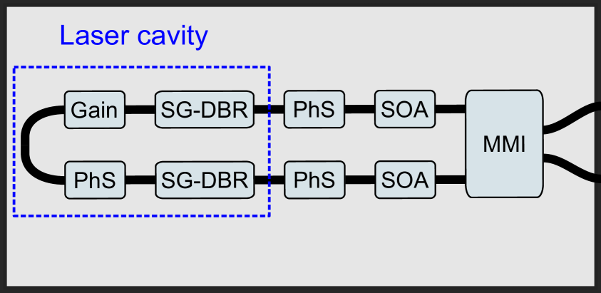
The U-shaped laser[39, 40] used in this work is a monolithically integrated InP photonic integrated circuit (PIC), which is shown schematically in Fig. 1 (a). The laser cavity (blue dashed line box) consists of a gain section and a phase shifter situated between two SG-DBR mirrors allowing tunability across the C-band. Light is emitted from both mirrors and combined by a 22 multi-mode interferometer (MMI) into the output waveguides of the PIC. Phase shifters are included in both arms to ensure constructive interference at the MMI, maximizing the output power. This simultaneously ensures constructive interference for the dual cavity feedback. Semiconductor optical amplifiers (SOAs) are also present in the output arms for further power amplification. The laser is mounted on a heat-sinking carrier connected to a custom current controller for tunability and optimization. A Peltier element beneath the carrier stabilizes the temperature at 23.5°C, where it is most stable, yielding a wavelength tunability range of 1513-1555 nm.
3.2 Optical feedback setup
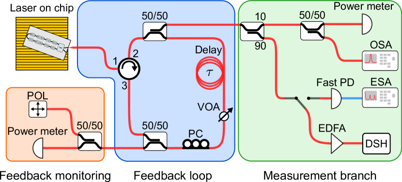
The setup used to inject optical feedback into the laser is shown in Fig. 1 (b). The output laser light of the PIC is collected by an anti-reflection coated lensed fiber which is connected to a circulator. A directional coupler then splits the light into two branches. One branch is the feedback loop (blue box) and the other branch is the measurement branch (green box). In the former, a variable optical attenuator (VOA, Thorlabs VOA50-APC) is used to control and adjust the optical feedback strength. A polarization controller (PC) is used to control the polarization of the feedback. After passing through these components, the light is then split again. One output provides optical feedback to the laser. The other output (orange box) is split 50:50 into a sensitive power meter (Thorlabs S154C) and a polarimeter (Thorlabs PAX1000IR2) to monitor the feedback power and polarization, respectively. In the measurement branch, 10 % is tapped off to measure the laser output power and wavelength by a power meter (Thorlabs S132C) and optical spectrum analyzer (OSA, Yenista OSA20), respectively. The remaining 90 % is either coupled into a fast photodetector (HP 11982A, 15 GHz bandwidth) going to an electrical spectrum analyzer (ESA, R&S FSW50) for RIN measurements, or passes through an erbium-doped fiber amplifier (EDFA, Lumibird-Keopsys CEFA) to ensure sufficient power for the DSH configuration (schematized in Fig. 1 (c)).
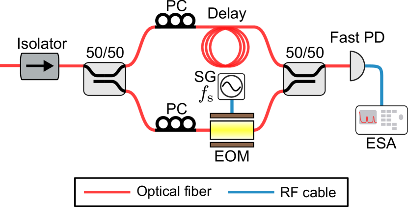
3.3 Self-coherent envelope linewidth detection
The DSH setup used for the SCELD method is shown in Fig. 1 (c), where the input light is split , sent through PCs to maximize the output of the electro-optic modulator (EOM, iXblue MPZ-LN-01) and subsequently optimize the constructive interference when recombining the unbalanced arms. This is then measured by a fast photodetector (Thorlabs PDA05CF2) and analyzed by an ESA (R&S FSW50).
Examples of Eq. 2 being used to extract linewidths, ranging from MHz to sub-kHz, with different delays are shown in Figs. 2 (a–d). The periodic ripples are separated by the inverse of the interferometer delay . Close to the carrier frequency (<200 kHz), the spectra are not well modeled by Eq. 2, where noise, other features from the FN power spectral density (PSD), and a delta peak appear [41]. This is especially evident in Fig. 2 (a) and Fig. 2 (b). Consequently, the spectra are fitted only for carrier detunings above kHz. For a given delay , the linewidth is determined by the height of these ripples. Deeper ripples indicate a more coherent signal and thus a lower linewidth as mentioned in Section 2.
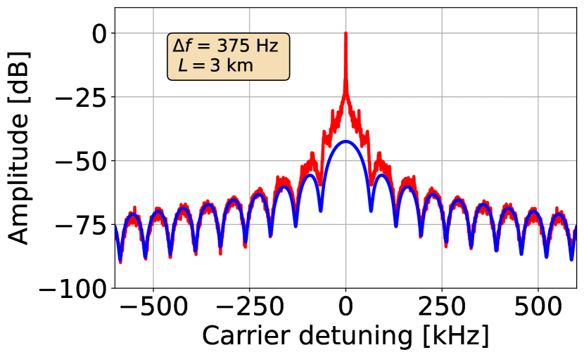
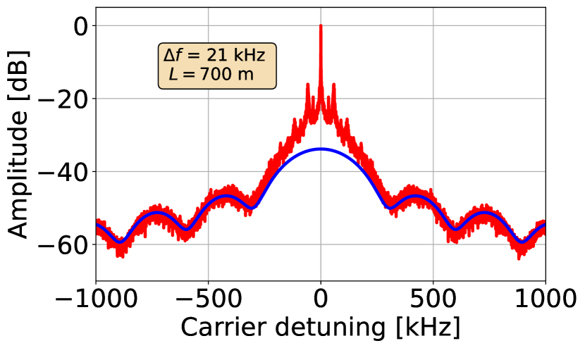
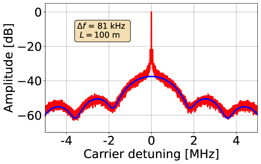
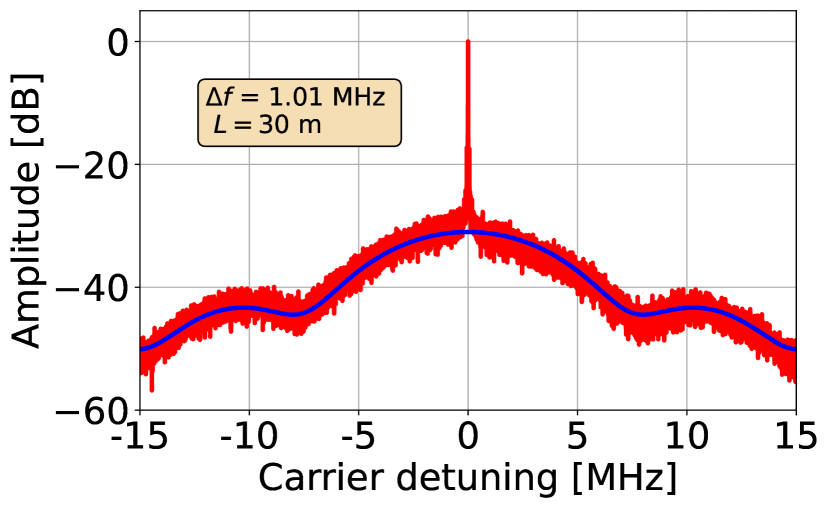
For a given linewidth, the delay should be chosen accordingly, as the amplitudes of the ripples depend on both. If the delay is too long the ripples disappear. On the other hand, a delay that is too short yields ripples that extend below the measurement noise floor. For example, a km delay can be used for linewidths between approximately Hz to kHz, whereas a m delay can measure linewidths ranging from kHz to several MHz.
3.4 Stability
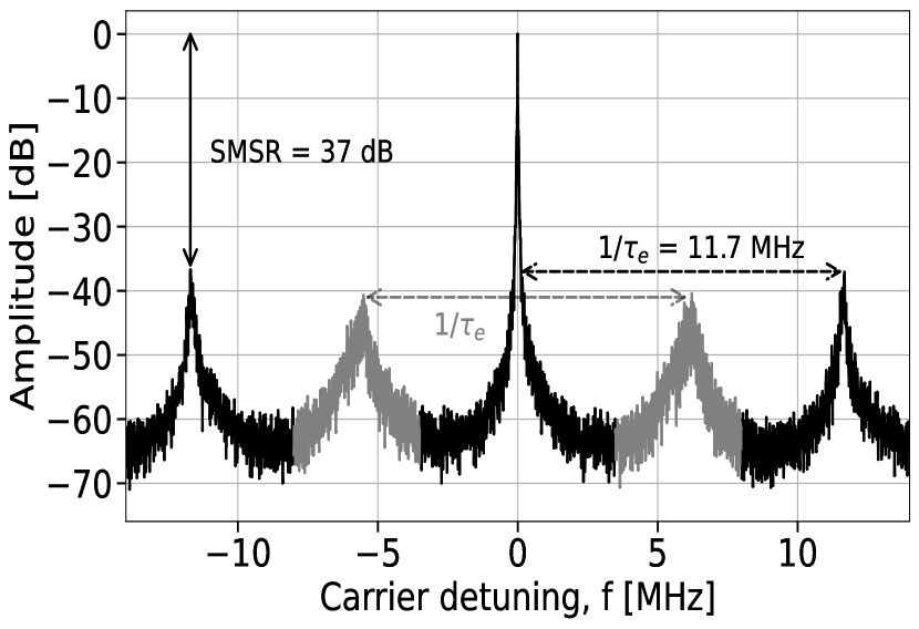
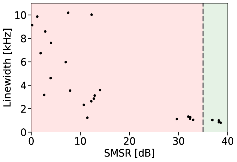
Linewidth narrowing using EOF depends critically on the overlap between the solitary cavity lasing mode and the external cavity modes (ECMs) due to the optical feedback path [22]. The ECMs appear on the ESA spectrum as a beat note between the lasing mode and neighboring ECMs, as exemplified in Fig. 2 (e). The m fiber feedback loop gives rise to a relatively narrow ECM separation with a free spectral range of MHz. Ambient temperature fluctuations cause both the ECMs and lasing wavelength to drift over time, leading to misaligned cavity modes and eventually a mode-hop to a neighboring ECM. In terms of Eq. 1 this mode overlap is modeled by the external feedback phase , from which a maximum linewidth reduction is achieved when the external feedback interferes constructively with the laser cavity field. In order to investigate how the overlap between the lasing mode and ECMs affect the linewidth, we monitored the SMSR and linewidth continuously for one minute as shown in Fig. 2 (f). We observe a significant linewidth broadening when the SMSR is low. There is also a gap between dB and dB SMSR. This gap can be explained by the onset of mode competition as the solitary laser cavity mode drifts in between two ECMs and there is a sudden jump in SMSR. Based on this, all our subsequent measurements will be done for SMSR dB to make sure that the laser remains single mode during linewidth measurements. Additionally, this ensures constructive feedback between the feedback and laser cavity fields, effectively eliminating the dependence in Eq. 1. This allows us to investigate how the linewidth evolves with feedback power without needing to take drift into account.
4 Results and Discussion
In this section, we present the experimental results and analysis of linewidth reduction and laser dynamics achieved through polarization-controlled EOF. Our focus lies on examining how feedback power influences the laser’s linewidth, relaxation oscillations, and overall output stability.
4.1 Linewidth versus feedback power
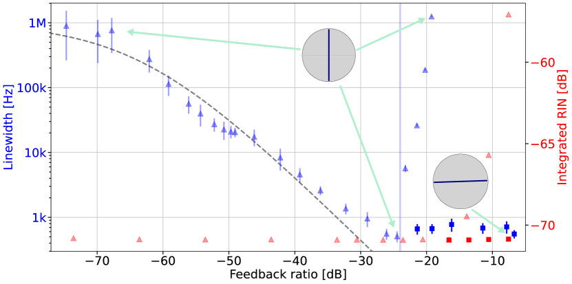
The primary objective of this work is to investigate the impact of polarization-controlled feedback on laser linewidth and stability, particularly under high feedback levels, pushing beyond the constraints of prior studies. Using the VOA, we attenuated the feedback ratios by up to dB. The laser operated with gain and SOA currents of mA and mA, respectively, producing 5 mW of fiber-coupled output power at a wavelength of 1549 nm. We obtained linewidth measurements using the SCELD method with various delays (as described in Section 3.3), ensuring single-mode operation with SMSRs exceeding dB (Section 3.4). For each feedback strength, we averaged 20 linewidth measurements, with uncertainties reflecting one standard deviation after removing outliers via the interquartile range method[42]. The resulting intrinsic linewidth measurements are shown against varying feedback power levels in Fig. 3 (a) as either blue triangles (aligned feedback) or blue squares (misaligned feedback).
The results reveal a linewidth reduction of more than three orders of magnitude, from MHz to sub-kHz, as feedback power increases. A theoretical fit to the data, based on Eq. 1 (grey dashed line), is plotted using the measured value of MHz for the intrinsic linewidth without feedback and as the fitting parameter. For feedback ratios up to approximately dB, increasing feedback levels resulted in progressively lower linewidths as indicated by the blue triangles. At these feedback levels, the feedback polarization was aligned with the laser output, to minimize the linewidth as predicted by Eq. 1. However, maintaining this polarization alignment at higher feedback levels led to CC, where the linewidth significantly broadened. By misaligning the feedback polarization, a linewidth plateau of around Hz can be maintained for higher feedback levels, as represented by the squares in Fig. 3 (a).
Misaligning the polarization decreases the coupling strength between the feedback and output fields. Consequently, by reducing the polarization overlap between the two fields as increases, the effective feedback can be kept just below the onset of CC. At the highest feedback ratio of dB, the feedback and laser output polarizations are nearly orthogonal, as evident from the insets in Fig. 3 (a).
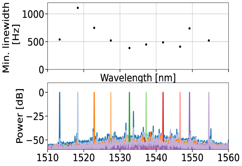
Next, by tuning the SG-DBR mirrors we modified the emission frequency across the full tunability range of the laser, as seen in the bottom of Fig. 3 (b). The fiber-coupled output power was increased to 10 mW by increasing SOA currents to 100 mA. For each wavelength, we measured the linewidth following the previously described method and optimized the polarization to yield the lowest possible linewidth. Results are shown in the top of Fig. 3 (b), demonstrating that the laser maintains narrow linewidths across its tuning range (1513 -1555 nm). Most wavelengths achieve a minimum linewidth of around 500 Hz for feedback ratios between dB and dB, which agrees with the linewidth plateau from Fig. 3 (a). We believe the discrepancy in linewidths across the different wavelengths can be reduced by more precise tuning of the mirror parameters and feedback polarization.
These results show intrinsic linewidths an order of magnitude lower than in similar studies on the U-shaped laser such as in Ref. [28], which examined the case of dual wavelength emission. Compared to that study, we have incorporated polarization control, more accurate intrinsic linewidth estimation, and single-mode filtering based on SMSR. Our results are also comparable to recent findings for an SG-DBR laser that filtered the feedback using a Sagnac ring and two coupled ring resonators[30]. They also achieved linewidth reductions by over three orders of magnitude (MHz to sub-kHz) with a comparable wavelength tuning range; however, our setup avoids the need for complex filtering components.
4.2 RIN versus feedback power
To further assess the laser’s stability, we monitored RIN spectra up to 10 MHz, avoiding ECMs, across all feedback ratios using the ESA, and with examples shown on Fig. 3 (c). For each measurement a single representative value was obtained by integrating over the spectra, from 2 MHz and onward to avoid technical noise, as reported on Fig. 3 (a) (red data points). RIN measurements confirm that CC was successfully circumvented, as the expected sharp increase in RIN is mitigated[43].
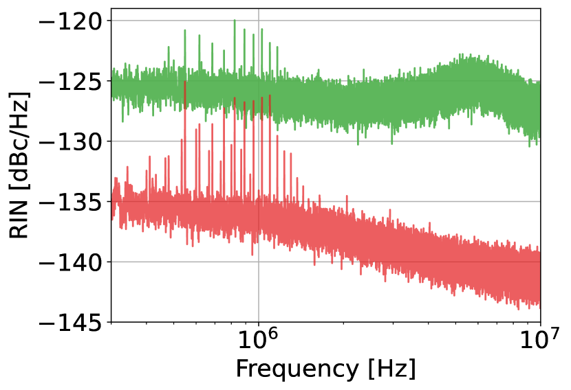
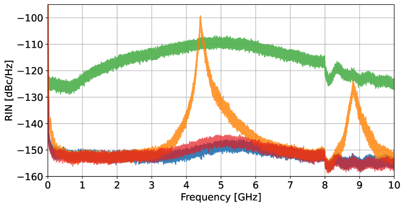
We performed further RIN measurements at the GHz range to confirm the mitigation of CC by monitoring the evolution of the relaxation oscillation frequency for different feedback levels and polarizations. The results are shown in Fig. 3 (d). The notch at 8 GHz and subsequent ripples are due to background noise.
| Gain (mA) | (GHz) | Coherence collapse onset (dB) | Minimum linewidth (Hz) |
| 1.3 | -50 | 20 k | |
| 2.6 | -36 | 2.2 k | |
| 3.9 | -29 | 840 | |
| 5.6 | -24 | 375 |
For no feedback (blue graph), is at 5.6 GHz, where it slightly decreases until the onset of CC. Increasing the feedback past CC while aligning the polarization to the laser output (orange graph) causes a further decrease in and an increase in the peak height and width. Furthermore, harmonics at integer multiples of appear, which are caused by the undamping of the relaxation oscillations, and are indicative of weak chaos [44]. A further increase in the aligned feedback (green graph) results in a broadening and increase of the RIN spectrum, which is indicative of strong chaos. For strong feedback, it is possible to mitigate the CC by misaligning the feedback polarization with the laser output polarization. This is evident from the strong, almost orthogonal feedback (red graph), which closely resembles the pre-CC spectrum (blue graph).
Strong chaos occurs when the feedback-induced lasing frequency shift overlaps with [44]. Thus, higher values indicate greater tolerance to coherent feedback, pushing the onset of CC. To demonstrate this, Table 1 shows how the laser’s properties depend on , which increases with increasing gain currents. With increasing values of , the onset of CC is pushed to higher feedback levels. The higher permissible coherent feedback and higher output powers allow us to achieve lower linewidths. In our case, going from mA to mA gain extends the onset of CC by dB and lowers the minimum achievable linewidth by nearly two orders of magnitude (from 20 kHz to 375 Hz).
4.3 Outlook
This work opens up several potential applications for feedback polarization control. One promising direction involves adding a Faraday rotator in the feedback loop and using a polarization-maintaining fiber to increase the laser’s robustness to feedback. By offsetting the polarization of the incoming feedback relative to the laser output, the feedback would exhibit weaker coupling to the lasing mode and thus remain in the pre-CC regime for stronger feedback levels, while yielding a narrowing of the linewidth and improved stability, making the laser more robust against feedback[26].
Increasing the length of the feedback loop (thus increasing ) would also introduce narrower linewidths according to Eq. 1, though it would also increase temperature fluctuations and decrease the mode spacing between the ECMs. Further work should investigate the relationship between feedback loop length, linewidth, and laser stability. Additionally, increasing the laser’s operational temperature using the Peltier element, and thereby shifting the tunability range, would allow us to measure the performance across the C+L-band.
5 Conclusion
In this work, we have demonstrated a dual-cavity feedback mechanism that effectively reduces the linewidth to the sub-kHz range across a wavelength tuning range of 42 nm using a U-shaped SG-DBR laser. We achieved this with a simple and cost-effective fiber-based external cavity, and attained a reduction of more than three orders of magnitude compared to the solitary cavity linewidth with SMSRs exceeding dB. By carefully varying the fraction of coherent feedback using polarization control, the amount of feedback can be increased beyond the usual onset of CC while still maintaining narrow linewidths and stable RIN. We confirmed this result by analyzing the properties of the laser, such as the relaxation oscillation frequency, under injection of various ratios of feedback for different laser gains and polarizations evidencing the robustness of the method. These results open new avenues for developing widely tunable, narrow-linewidth lasers with strong optical feedback.
Funding Innovation Fund Denmark (Grand Solutions project GreenCOM)
Acknowledgments The authors want to thank James Christensen at OE Solutions America, Inc. for his helpful feedback and valuable discussions, which improved the quality of this work. We also appreciate OE Solutions for supplying the U-shaped lasers and accompanying test equipment, as well as their support throughout our research.
Disclosures The authors declare no conflicts of interest.
Data Availability Statement Data underlying the results presented in this paper may be obtained from the authors upon reasonable request.
References
- [1] A. Jørgensen, D. Kong, M. Henriksen, et al., “Petabit-per-second data transmission using a chip-scale microcomb ring resonator source,” \JournalTitleNature Photonics 16, 798–802 (2022).
- [2] M. Seimetz, “Laser linewidth limitations for optical systems with high-order modulation employing feed forward digital carrier phase estimation,” in Optical Fiber Communication Conference/National Fiber Optic Engineers Conference, (Optica Publishing Group, 2008), p. OTuM2.
- [3] P. Holewa, D. A. Vajner, E. Zięba-Ostój, et al., “High-throughput quantum photonic devices emitting indistinguishable photons in the telecom c-band,” \JournalTitleNature Communications 15, 3358 (2024).
- [4] M. Avesani, L. Calderaro, M. Schiavon, et al., “Full daylight quantum-key-distribution at 1550 nm enabled by integrated silicon photonics,” \JournalTitlenpj Quantum Inf. 7, 93 (2021).
- [5] J. Riemensberger, A. Lukashchuk, M. Karpov, et al., “Massively parallel coherent laser ranging using a soliton microcomb,” \JournalTitleNature 581, 164–170 (2020).
- [6] Q.-F. Yang, B. Shen, H. Wang, et al., “Vernier spectrometer using counterpropagating soliton microcombs,” \JournalTitleScience 363, 965–968 (2019).
- [7] N. Jones et al., “How to stop data centres from gobbling up the world’s electricity,” \JournalTitleNature 561, 163–166 (2018).
- [8] F. Hamaoka, M. Nakamura, S. Okamoto, et al., “Ultra-wideband wdm transmission in s-, c-, and l-bands using signal power optimization scheme,” \JournalTitleJournal of Lightwave Technology 37, 1764–1771 (2019).
- [9] J. Nie, T. Yang, L. Wang, et al., “Simultaneous linewidth narrowing for integrated chip of dfb laser array based on self-injection feedback,” \JournalTitleOptics Communications p. 131086 (2024).
- [10] H. Zhao, S. Pinna, B. Song, et al., “Indium phosphide photonic integrated circuits for free space optical links,” \JournalTitleIEEE Journal of Selected Topics in Quantum Electronics 24, 1–6 (2018).
- [11] J. Renaudier, A. Napoli, M. Ionescu, et al., “Devices and fibers for ultrawideband optical communications,” \JournalTitleProceedings of the IEEE 110, 1742–1759 (2022).
- [12] J. Guo, C. A. McLemore, C. Xiang, et al., “Chip-based laser with 1-hertz integrated linewidth,” \JournalTitleScience Advances 8, eabp9006 (2022).
- [13] M. H. Idjadi and F. Aflatouni, “Nanophotonic phase noise filter in silicon,” \JournalTitleNature Photonics 14, 234–239 (2020).
- [14] W. Lewoczko-Adamczyk, C. Pyrlik, J. Häger, et al., “Ultra-narrow linewidth dfb-laser with optical feedback from a monolithic confocal fabry-perot cavity,” \JournalTitleOptics Express 23, 9705–9709 (2015).
- [15] D. K. Shin, B. M. Henson, R. I. Khakimov, et al., “Widely tunable, narrow linewidth external-cavity gain chip laser for spectroscopy between 1.0–1.1 m,” \JournalTitleOptics Express 24, 27403–27414 (2016).
- [16] R. R. Kumar, A. Hänsel, M. F. Brusatori, et al., “A 10-khz intrinsic linewidth coupled extended-cavity dbr laser monolithically integrated on an inp platform,” \JournalTitleOptics Letters 47, 2346–2349 (2022).
- [17] M. Far Brusatori, D. N. Duplat, I. Degli-Eredi, et al., “Ultralow-linewidth ring laser using hybrid integration and generic foundry platforms,” \JournalTitleOptics Letters 47, 2686–2689 (2022).
- [18] M. A. Tran, C. Zhang, T. J. Morin, et al., “Extending the spectrum of fully integrated photonics to submicrometre wavelengths,” \JournalTitleNature 610, 54–60 (2022).
- [19] A. Prokoshin, M. Gehl, S. Madaras, et al., “Ultra-narrow-linewidth hybrid-integrated self-injection locked laser at 780 nm,” \JournalTitleOptica 11, 1024–1029 (2024).
- [20] S. Huang, T. Zhu, G. Yin, et al., “Dual-cavity feedback assisted dfb narrow linewidth laser,” \JournalTitleScientific Rep. 7, 1185 (2017).
- [21] D. Brunner, R. Luna, A. D. i Latorre, et al., “Semiconductor laser linewidth reduction by six orders of magnitude via delayed optical feedback,” \JournalTitleOpt. Lett. 42, 163–166 (2017).
- [22] K. Petermann, “External optical feedback phenomena in semiconductor lasers,” \JournalTitleIEEE Journal of Selected Topics in Quantum Electronics 1, 480–489 (1995).
- [23] S. Donati and R.-H. Horng, “The diagram of feedback regimes revisited,” \JournalTitleIEEE Journal of Selected Topics in Quantum Electronics 19, 1500309–1500309 (2013).
- [24] D.-L. Cheng, T.-C. Yen, J.-W. Chang, and J.-K. Tsai, “Generation of high-speed single-wavelength optical pulses in semiconductor lasers with orthogonal-polarization optical feedback,” \JournalTitleOptics Communications 222, 363–369 (2003).
- [25] N. Oliver, M. C. Soriano, D. W. Sukow, and I. Fischer, “Dynamics of a semiconductor laser with polarization-rotated feedback and its utilization for random bit generation,” \JournalTitleOptics Letters 36, 4632–4634 (2011).
- [26] H. Yasaka, Y. Yoshikuni, and H. Kawaguchi, “Fm noise and spectral linewidth reduction by incoherent optical negative feedback,” \JournalTitleIEEE Journal of Quantum Electronics 27, 193–204 (1991).
- [27] R. Ju and P. S. Spencer, “Dynamic regimes in semiconductor lasers subject to incoherent optical feedback,” \JournalTitleJournal of Lightwave Technology 23, 2513 (2005).
- [28] M. Far Brusatori, H. N. Klein, and N. Volet, “Achieving high stability of dual-wavelength u-shaped laser in the c-band using optical feedback,” \JournalTitleIEEE Photonics Technology Letters 35, 573–576 (2023).
- [29] L. Sheng, J. Wang, L. Huang, et al., “Advances in narrow linewidth and wide tuning range external-cavity wavelength-swept lasers,” \JournalTitleFrontiers in Physics 12 (2024).
- [30] J. Wang, B. Chen, D. Ban, et al., “Widely tunable narrow-linewidth laser based on a multi-period-delayed feedback photonic circuit,” \JournalTitleIEEE Photonics Technology Letters 36, 437–440 (2024).
- [31] C. Henry, “Theory of the linewidth of semiconductor lasers,” \JournalTitleIEEE Journal of Quantum Electronics 18, 259–264 (1982).
- [32] D. Lenstra, B. Verbeek, and A. Den Boef, “Coherence collapse in single-mode semiconductor lasers due to optical feedback,” \JournalTitleIEEE Journal of Quantum Electronics 21, 674–679 (1985).
- [33] R. Lang and K. Kobayashi, “External optical feedback effects on semiconductor injection laser properties,” \JournalTitleIEEE Journal of Quantum Electronics 16, 347–355 (1980).
- [34] R. de Mey, S. W. Jolly, and M. Virte, “Clarifying the impact of dual optical feedback on semiconductor lasers through analysis of the effective feedback phase,” \JournalTitleChaos 34, 043142 (2024).
- [35] M. Far Brusatori and N. Volet, “Dynamics of semiconductor lasers under external optical feedback from both sides of the laser cavity,” \JournalTitlePhotonics 9, 43 (2022).
- [36] L. Mercer, “1/f frequency noise effects on self-heterodyne linewidth measurements,” \JournalTitleJournal of Lightwave Technology 9, 485–493 (1991).
- [37] Z. Zhao, Z. Bai, D. Jin, et al., “Narrow laser-linewidth measurement using short delay self-heterodyne interferometry,” \JournalTitleOpt. Express 30, 30600–30610 (2022).
- [38] T. Okoshi, K. Kikuchi, and A. Nakayama, “Novel method for high resolution measurement of laser output spectrum,” \JournalTitleElectronics Letters 16, 630–631 (1980).
- [39] H. N. Klein and N. Volet, “Method for narrowing the linewidth of a single mode laser by injecting optical feedback into the laser cavity through both laser cavity mirrors,” US Patent 11,522,339. December 6, 2022.
- [40] D. J. Blumenthal, “Tunable u-laser transmitter with integrated mach-zehnder modulator,” US Patent 9,755,753. September 5, 2017.
- [41] S. T. Thomsen, M. F. Brusatori, N. H. Arent, et al., “Frequency noise measurements using coherent self-heterodyne detection,” \JournalTitleOpt. Lett. 48, 6372–6375 (2023).
- [42] S. R. Sørensen, E. Z. Ulsig, F. E. Philip, et al., “Open-source toolbox for photographic characterization of optical propagation,” \JournalTitleOpt. Lett. 49, 4098–4101 (2024).
- [43] T. S. Rasmussen, Y. Yu, and J. Mork, “Suppression of coherence collapse in semiconductor fano lasers,” \JournalTitlePhys. Rev. Lett. 123, 233904 (2019).
- [44] X. Porte, M. C. Soriano, and I. Fischer, “Similarity properties in the dynamics of delayed-feedback semiconductor lasers,” \JournalTitlePhysical Review A 89, 023822 (2014).